- 1State Key Laboratory of Transient Optics and Photonics, Xi’an Institute of Optics and Precision Mechanics (XIOPM), Chinese Academy of Sciences, Xi’an, China
- 2University of Chinese Academy of Sciences, Beijing, China
The deployment of low earth orbits is seen as a promising way of enlarging data capacities as well as high data rates. Catering to these interests, optical communication presents possible ways of larger bandwidth than microwave communication. The current generation of mainstream communication systems are classified as coherent systems and incoherent systems, and in particular, coherent systems have received more attention owing to their high receiving sensitivity. This study investigates a digital coherent transceiver, based on binary phase-shift keying technology. As coherent demodulation will be affected by considering the Doppler shift effect in digital demodulation, Doppler shift of ± GHz can be compensated by adopting a two-stage frequency offset compensation. Moreover, by leveraging a fast filtering algorithm a considerable amount of resource consumption is saved in its engineering implementation, and its sensitivity can be significantly enhanced via a high-speed parallel error-correction codec based on low-density parity-check technology.
1 Introduction
In recent years, with the growth of terrestrial communication technology, free-space optical communication has been given more attention due to its advantages such as a wide bandwidth, high speed, high data rates, and low latency [1, 2]. As a complementary technology to augment the network capability of terrestrial communication systems, satellite communication is advantageous terms of broad coverage, long transmission distance, and agile networking capabilities, rendering a near-seamless coverage for regions such as oceans, mountains, and plateaus, while catering to the demands of various users for communication coverage. Therefore, satellite communication holds significant commercial value [3, 4]. Notably, low earth orbit (LEO) satellites have been employed for commercial networking endeavors, such as Starlink and OneWeb, on a large scale owing to its benefits in terms of low orbital height, short transmission delay, low spatial path loss, and low launch cost. Compared to conventional modes of microwave communication technology, laser-based space communication technology utilizes lasers for information transmission, featuring a large bandwidth, low power consumption, small size and high confidentiality. Considering its advantages, this technology has attracted increasing attention as a worldwide research topic [5]. Currently, conventional modes of LEO laser-communication system consists of three parts: optical antenna, tracking equipment, and optical communication terminal. In the aspect of communication systems, modulation modes such as intensity modulation (IM), differential phase-shift keying (DPSK) and binary phase-shift keying (BPSK) are commonly employed. In this perspective, the BPSK system based on coherent detection (CD) demonstrates a communication sensitivity approaching the shot-noise limit (9 photons/bit), which can support inter-satellite laser communication over a distance of thousands of kilometers [6]. However, Doppler shift, dispersion, and energy attenuation may occur in the transmission process, as well as the frequency deviation in clocks at both ends of the transmitter and receiver, all of which will ultimately deteriorate the communication performance. Therefore, this study focused on the rational design of optical communication equipment in space by ensuring proper compensation of Doppler shift, dispersion, and time offset. The parallel processing in baseband segment is needed as the sampling rate of the digit signal exceeding the clock when the symbol rate corresponding to laser communication is generally greater than 1 Gbps. Furthermore, an implementation with a relatively small resource consumption should also be considered.
2 Materials and methods
2.1 Method
A coherent optical communication system is based on coherent detection and corresponding modulation mode. For coherent detection, the photodetector in the receiver is responsive to the light field generated by the superposition of local oscillator (LO) light and signal light. The system signal-to-noise ratio needs to be optimized by the spatial coherence between the stronger LO light and the received signals light, in order to enhancing the detection sensitivity of the system (as illustrated in Figure 1) [7]. The expressions of the time-domain signal for signal light and LO light are as follows [8]:
where,
Assuming that the transmission direction and polarization direction of signal light
where, R represents the responsivity of the photodetector, and
The aforementioned equation contains the overall information of signal light and LO light field. Herein,
As listed in Table 1, with the same bit error rate (BER), the required photon-bit number of BPSK light homodyne is evidently smaller, while those of direct detection and DPSK heterodyne demodulation are larger. Therefore, the coherent BPSK-based homodyne optical receiver serves as the optimal choice to enhance the receiving sensitivity of long-distance laser communication systems.

TABLE 1. Shot-noise-limited sensitivity of various types of coherent optical-communication receivers at a 1.0 × 10−9 bit error rate (BER).
2.2 Doppler effect
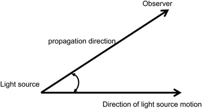
Spatially coherent communication, which requires a stable frequency difference, cannot compensate the random changes in frequency difference so that the eventual coherent demodulation has been affected significantly which leading to a deterioration of the BER. In space, Doppler shift is generated by the relative motion between satellites with different orbits and between the satellite and earth [10–12]. Moreover, the phase error originating from the Doppler shift varies rapidly, which may reach the GHz-scale, thereby causing a variation in the phase difference. Presumably, the laser source moves at a relative velocity of v along V direction, while the angle between V and the propagation direction of the optical carrier is θ, as illustrated in Figure 2.
The frequency shift of the Doppler spectrum can be mathematically derived through Lorentz transformation [13]:
where,
Particularly, the Doppler frequency shift is considerable and can vary rapidly. When an identical frequency exists, the frequency drift is induced by signal interference has a fast time-varying nature. Therefore, the Doppler frequency shift, in this case, will directly affect the received useful signal, and then impacting the receiving quality. In coherent systems, the LO and intermediate frequency (IF) of signals are actually processed, whereas as a desirable condition, IF should merely vary with different modulation modes under investigation. However, random IF shifts may occur due to the deleterious effects of various noises. The Doppler shift serves as the factor generating enormous IF shifts which enen as introducing considerable noise interference. This phenomenon can significantly impact the demodulation of coherent systems and eventually lead to a bad effect on BER, which jeopardizes the coherent performance and system stability. Therefore, compensation on Doppler shift is definitely required to ensure reliable communication.
With the advancement of digital signal processing (DSP), compensation techniques based on DSP for frequency and phase offset have been extensively investigated and developed [14–17], whose preemptive characteristic is that the system adopts open-loop compensation to compensate frequency and phase offset without using of an optical phase locked loop (OPLL). The compensation of Doppler shift in space has been performed in this study. In our works, Fast Fourier transform (FFT) frequency shift is used to estimate the wavelength of the LO laser so that the frequency offset of the carrier ring can be compensated which will solve the issue of Doppler shift in laser-based space communication systems.
2.3 Experimental setup
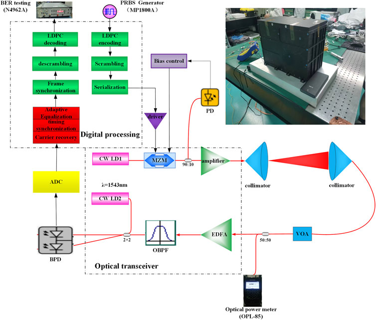
The following scheme was adopted for the experiment in this paper. The structure of BPSK-based coherent optical communication comprises three parts: the transmitter part, space-channel part, and the receiver part. As illustrated in Figure 3, the transmitter part of BPSK includes a 1.25 Gbps data-signal channel, a laser of band 1,550 with a line-width of 10 kHz, an electric-driven amplifier, and a Mach–Zehnder modulator (MZM). The digital signal is generated through a field-programmable gate array (FPGA), which subsequently transfers to the electric-driven amplifier after low-density parity-check (LDPC) encoding, data scrambling, framing, and other processing methods. Following amplification, the data is fed back to the MZM for electro-optical modulation, and the output optical signal is transmitted via the optical antenna. If the signal’s optical power is attenuated due to long-distance transmission along the space channel, signals received by the optical antenna shall be amplified and filtered using an erbium-doped fiber amplifier (EDFA) and an optical filter before reaching to the receiver system. Subsequently, the received signal light and LO light are mixed by a 180° frequency mixer. Thereafter, the mixed optical signals are converted into electrical signals using a balanced detector, and electrical signals, as the output of the detector at this moment, are conveyed as radio-frequency signals after down-conversion. Finally, the signals are sampled via a high-speed analog-to-digital converter (ADC) and then processed using a digital processor.
Considering the miniaturization and convenience of use, the FPGA is adopted to digitally perform high-speed parallel demodulation. As illustrated in Figure 4A, the entire processing procedures include carrier recovery, timing synchronization and self-adaptive equalization. The acquired digits after equalizing are baseband signals for the subsequent frame synchronization, data scrambling, and LDPC decoding. Subsequently, the bit error test is conducted on the decoded valid digits. The implementation of digital demodulation and LDPC are emphasized in the following sections.
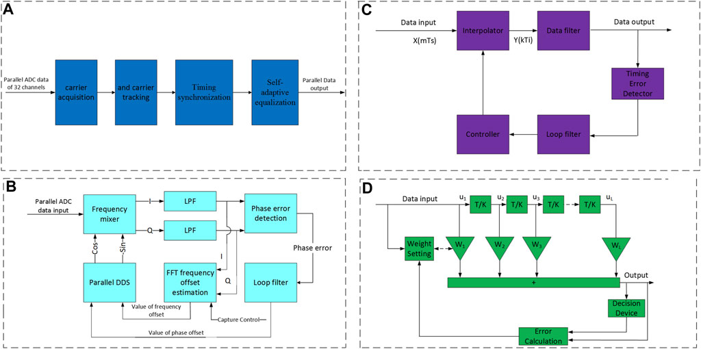
FIGURE 4. (A) Block diagram of BPSK digital demodulation. (B) Carrier recovery. (C) Parallel Gardner synchronization. (D) LMS equalizer.
2.3.1 Carrier recovery
Carrier recovery can be divided into two sections: carrier acquisition and carrier tracking. As illustrated in Figure 4B, two-stage FFT frequency scanning is adopted for carrier acquisition to realize ± 625-MHz wide range frequency compensation. The intermediate frequency carrier is matched by the direct digital synthesizer (DDS) frequency. After frequency mixing and filtering, the frequency offset is calculated by reducing the signal sampling rate and Fourier transform. The point with the maximum FFT power corresponds to the frequency offset position. The compensation is realized by adjusting the local oscillator laser wavelength considering the wavelength adjustment error and compensation accuracy.
In the second stage, we adopt the same method to modify the above setting parameters so as to meet a ±100-MHz accuracy frequency offset compensation. Having estimated the coarse frequency offset induced by the Doppler shift and wavelength adjustment error, the DDS frequency is set as the estimated value, and the system enters the loop-tracking stage. As the acquisition module cannot determine the start time for re-acquisition, the acquisition should be controlled using the frame synchronization module. The acquisition is conducted every second when the system is not in the frame-synchronization status.
2.3.2 Timing synchronization
The parallel-timing synchronizer is illustrated in Figure 4C, which is implemented by exploiting the Gardner synchronization algorithm. This strategy is used to extract the deviation between the transmitter clock and the asynchronous sampling clock for clock recovery, ensuring that the sampling data is maintained at the optimal sampling point. In the system, each channel possesses an independent numerically-controlled oscillator (NCO) and an interpolator. Here, Lagrangian interpolation is used to achieve a higher precision than oversampling. Error detection is performed after aligning the interpolation results, and the timing error is stabilized in a short time. The error is directly accumulated and is subsequently fed back to the loop filter. An additional consideration is that the timing error should match our loop filter for the best results. The loop filter is used to filter the high-frequency components and error signal smoothing. Additionally, it is adopted to adjust the NCO, whose output controls the interpolation position.
2.3.3 Self-adaptive equalization
The serial structure of a least mean square (LMS)-type self-adaptive equalizer is illustrated in Figure 4D. The parallel structure is similar to the serial structure, with the exception that the filter and the decision maker are switched to a parallel configuration. As no training sequence is set in the frame structure and the signal is continuous, the LMS equalizer does not perform training but directly decides the feedback to update the filter coefficients.
The signals entering the self-adaptive filter are signals with doubled symbol rate after timing. After the filtering process, the decision step is performed for every second point of signals, and the decision results are mapped as constellation points. Moreover, error signals are acquired by subtracting the constellation points from the decision results. By introducing error signals to the update equation, the filter coefficient is accordingly updated. After multiple decision-making, error acquisition, and coefficient updating, the filter coefficient will be stabilized at status with a small mean-square error.
2.3.4 LDPC error correction
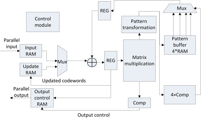
The LDPC code features excellent characteristics, including approaching the Shannon limit, high convergence rate, and high bandwidth efficiency, which empowers the high-speed long-distance optical communication system by greatly enhancing its sensitivity. Considering the resource consumption and implementation, serial-bit-flip (SBF) algorithm was employed in this experiment to enable the hard decision of LDPC. The overall structure of the encoder is illustrated in Figure 5A. Herein, S-ENCODER represents the serial encoder, whose structure is displayed in Figure 5B. The implemented structure of shift-register-adder-accumulator (SRAA) is demonstrated in Figure 5C. With a clock frequency of 125 MHz, the serial encoder of each channel can achieve a code throughput of 125 Mbps. The structure of parallel decoder is illustrated in Figure 6. It mainly includes input buffer, update buffer, output buffer, mode buffer, adder, multiplexer, matrix multiplier and comparator. The decoding result is obtained by computing the adjoint matrix through multiple iterations.
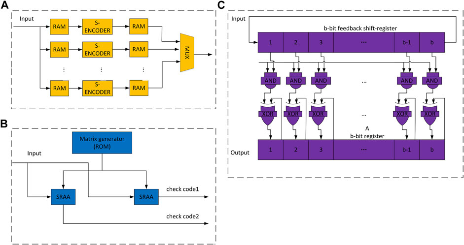
FIGURE 5. (A) Block diagram of the encoder. (B) Structure of the serial encoder. (C) Encoder with a structure of shift register adder accumulator.
3 Simulation
Considering resource consumption and feasibility, the digital demodulation and error correction algorithm of this experiment was first simulated in MATLAB. We used a 1.6-GHz IF and 1.2497-Gbps symbol rate as the input RF data collected by the ADC to verify the implementation effect of carrier recovery and bit synchronization. The transmission symbols are square waves and have reached the maximum bandwidth. In this simulation design, the frequency offset, which is caused by different oscillator frequencies between the transmitter and receiver and by Doppler effects, is implemented via two-stage compensation. In the first stage, we estimate a rough large-frequency offset and then adjust the local oscillator laser wavelength in the actual system. Then, only the second stage and subsequent algorithms are implemented in the simulation. The floating-point simulation results are listed in Table 2, in which the total data sample size is 2 × 106 bits. The simulation results indicate that the method adopted in this experiment is close to the theoretical results. The receiving sensitivity after demodulation mainly depends on the signal-to-noise ratio (SNR) of the input signal. As long as the frequency offset is in the capture range, it has little impact on the bit error rate.
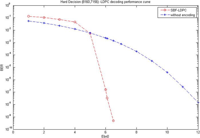
In the simulation, when Eb/N0 = 10, the spectra and constellation diagrams of certain signals are illustrated in Figure 7. In the actual system, the constellation results can be used to evaluate the influence of signal-level characteristics, noise, and inter-symbol interference (ISI). The results of SBF algorithm after 20 iterations are illustrated in Figure 8. The SBF algorithm exhibits a BER lower than 10–7 at 6.1 dB, while the undecoded approach renders a BER of 10–7 at 11.3 dB. Therefore, with a BER of 10–7, the SBF algorithm demonstrates a gain of 5.2 dB. By adopting the same calculation approach, the gain is approximately 4.5 dB, with a BER of 10–6 and approximately 3.5 dB with a BER of 10–5.
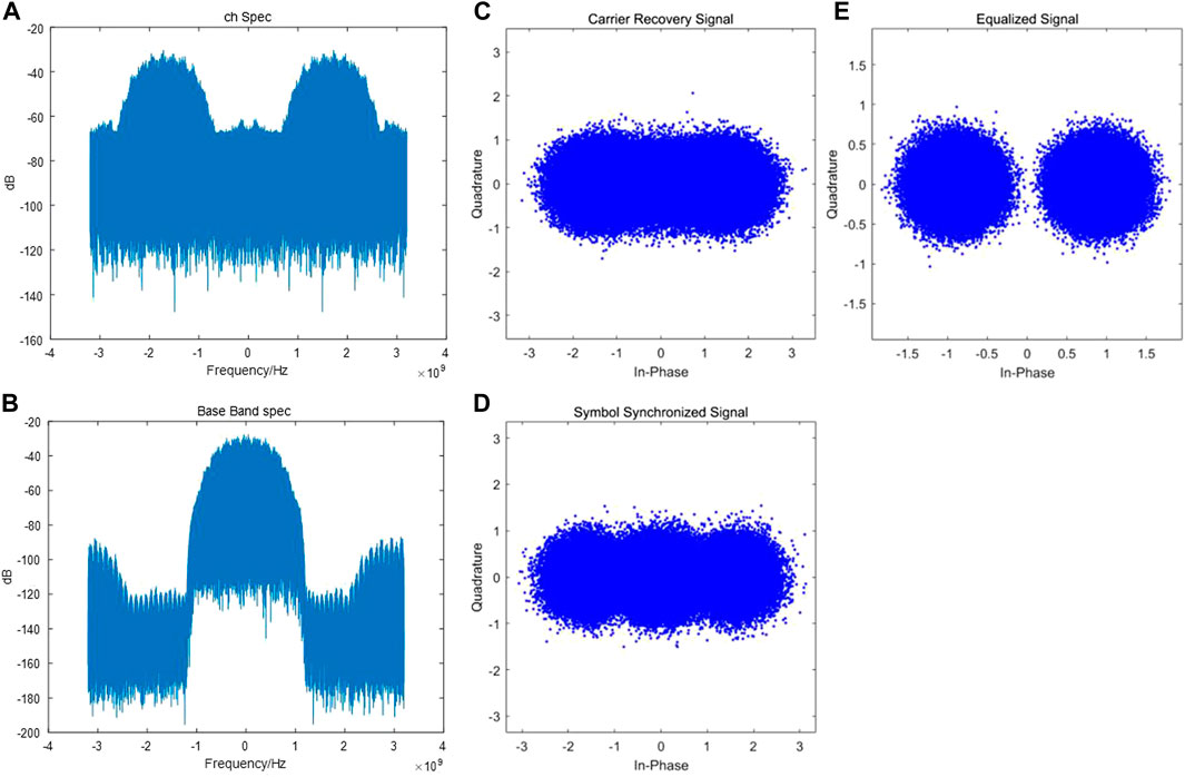
FIGURE 7. (A) IF signal spectrum. (B) Baseband frequency spectrum after carrier recovery. (C) Constellation diagram after carrier recovery. (D) Constellation diagram after timing synchronization. (E) Constellation diagram after equalization.
4 Results and discussion
4.1 Resource analysis for implementation
In the stage of carrier recovery, the COordinate Rotation DIgital Computer (CORDIC) algorithm is adopted by the parallel DDS for implementation without requiring any hardware multiplier (DSP). The frequency mixer consists of two parts: I and Q, and each part has 32 parallel channels and 64 DSP in total. The FFA decomposition algorithm is used in the LPF, as illustrated in Figure 9. Two filters with a length of N can be decomposed into 3 filters with a length of N/2, thereby decreasing the DSP cost from 4N to 3 N. Moreover, a 64-order FIR filter is adopted in practice with 32 parallel channels, which can be decomposed five times with the DSP quantity =
In the timing synchronization stage, linear interpolation is adopted using the interpolator with two DSPs in each channel and 64 DSPs for 32 channels in total. With a sampling rate of 10 Gbps and a symbol rate of 1.25 Gbps, 10/1.25 symbols exist for 32 points. Furthermore, by considering the boundary and time offset, the DSP cost of error estimation =
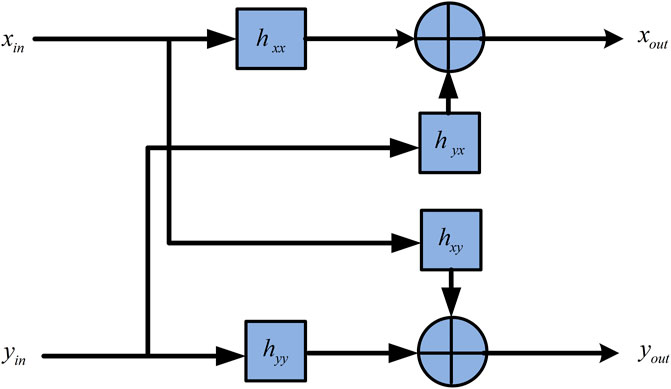
In the self-adaptive equalization stage, the equalization filter is a complex filter, as demonstrated in Figure 10. The implementation of one complex filter is equivalent to implementing four real filters. Signals from
Therefore, the number of DSPs required for digitally coherent demodulation is calculated as 1,040 + 84 + 668 = 1792. In this experiment, an FPGA obtained from Xilinx, Inc. (type: VU9P) was employed for design implementation. This resource could effectively fulfill the research demands.
In the LDPC part, the encoder comprises 10 serial encoders and 20 buffer RAM in total for the input and output operations. As the circulant submatrix in (8160, 7136), the LDPC has a dimension of 511, and each SRAA requires 511 lookup tables (LUTS) and 1,022 registers. The matrix generator requires approximately 150 LUTS, and a serial encoder requires approximately 1200 LUTS and one 18K-RAM. Moreover, 3000 LUTS are reserved for the parallel-to-serial conversion and control circuit of the encoder. With a working clock frequency of 125 MHz, the total resource requirements of the encoder comprise 30,000 LUTS and 60 18-RAMs. Additionally, the decoder stage involves 511 parallel decoders comprising multiplier, adder, pattern transformer, comparator, and RAM. According to statistics, with a clock of 125 MHz, 50,240 LUTS and 35 18k-RAMs are required.
4.2 Discussion
The receiving sensitivity is an essential indicator of the performance of the free-space optical receiver. At the receiving end, the received input-light power is monitored by a 50:50 beam splitter, and bit error tests are conducted simultaneously. By manipulating the attenuated energy of the attenuator, the input light power at the receiving end is varied from −52 to −47 dBm, then we test the receiver performance sequentially. A BPSK constellation diagram obtained via demodulation without encoding and a sensitivity of −40 dBm is illustrated in Figure 11A. It can be seen that the noise introduced by the low-noise optical amplifier and the balance detector cause a large EVM value after demodulation (the data distribution is not concentrated in the white circle in the figure). The eye map distribution after demodulation, which is a communication performance evaluation method, is illustrated in Figure 11B. In the figure, a thicker eyelid of eye diagram can be obviously found, which is due to the distortion of the maximum signal at the sampling time. Moreover, the over-zero point at the intersection of the two oblique lines can express the characteristics of the signal response in the time domain, indicating whether the upward and descending time of the signal is symmetric and whether the duty cycle is 50%. In this experiment, the final demodulation signal was slightly distorted by the detector and the limited bandwidth of the ADC sampling chip.
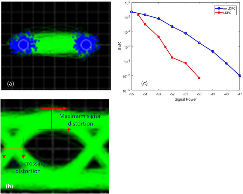
FIGURE 11. (A) Constellation diagram for a 1.25-Gbps BPSK signal. (B) Eye diagram for a 1.25-Gbps BPSK signal. (C) BER for a 1.25-Gbps BPSK signal.
Bit error tests are conducted on the original pseudorandom binary sequence data before encoding and the encoded data. Figure 11 depicts the bit error test results. With a BER of 10−7 as the benchmark, the receiving sensitivity without LDPC encoding attained a value of −49 dB, while the BER reached −52 dBm after LDPC encoding. Notably, compared to the theoretical limit, only a loss of −4 dBm occurs as 56 dBm.Compared with the similar experiment work recently we know [18], our current test results are about 1 dB better than them. In terms of the coding gain, the simulation results demonstrated that by employing the SBF algorithm, when the BER magnitude was in the scale of 10–7, the coding gain in the actual experiment was 3.5 dB (the theoretical gain is close to 5 dB), for which the error might be attributed to issues involving the actual system’s SNR and baseband signal quality after recovery. In our system, the sensitivity gap is mainly attributed to the noise factor of 4.5 dB introduced by the optical preamplifier, as the theoretical value is 3 dB. In terms of electronics, the quantizing noise generated by the high-speed ADC, circuit design noise, clock stabilization, and digital demodulation noise are considered herein.
5 Conclusion
This study proposed a method for enhancing the receiver sensitivity of coherent free-space optical (FSO) communication systems, which was enabled by BSPK technology based on LDPC encoding. The following results were obtained: the Doppler effect, resulting from the relative motion between satellites, could be properly addressed by using the proposed two-stage frequency-offset compensation. With a data rate of 1.25 Gbps corresponding to optical communication, the performance rendering the optical receiving power of −52 dBm and BER of 10–7 could be achieved through the proposed system. In addition, Considering the resource consumption and implementation for high speed, serial-bit-flip (SBF) algorithm was employed in this experiment to enable the hard decision of LDPC. When the BER magnitude was in the scale of 10–7, the coding gain in the actual experiment was 3.5 dB. It is better than Reed-solomon encoding. Different from conventional DPSK and OOK, the LDPC-encoded BPSK approach yielded a high level of receiving sensitivity in FSO communication, which further demonstrated its superior feasibility. Moreover, the Doppler shift, resulting from the relative motion between satellites, could be solved via the proposed two-stage frequency compensation. Notably, the findings of this experiment can offer reliable technical support for the subsequent construction of FSO communication systems.
Data availability statement
The raw data supporting the conclusion of this article will be made available by the authors, without undue reservation.
Author contributions
All authors listed have made a substantial, direct, and intellectual contribution to the work and approved it for publication.
Funding
This work is supported by National Key Research and Development Program of China (2022YFB2803203).
Conflict of interest
The authors declare that the research was conducted in the absence of any commercial or financial relationships that could be construed as a potential conflict of interest.
Publisher’s note
All claims expressed in this article are solely those of the authors and do not necessarily represent those of their affiliated organizations, or those of the publisher, the editors and the reviewers. Any product that may be evaluated in this article, or claim that may be made by its manufacturer, is not guaranteed or endorsed by the publisher.
References
1. Wang Y, Li X, Jiang Z, Tong L, Deng W, Gao X, et al. Ultrahigh-speed graphene-based optical coherent receiver. Nat Commun (2021) 12(1):5076–7. doi:10.1038/s41467-021-25374-0
2. Ding Y, Wang H, Yuefeng J. Experimental demonstration of all-optical aggregation and de-aggregation for a QPSK signal in an elastic optical network. Opt Express (2022) 30(5):6456–68. doi:10.1364/oe.446308
3. Wang L, Wang J, Tang X, Chen H, Chen X. Performance analysis of a spatial diversity coherent free-space optical communication system based on optimal branch block phase correction. Opt Express (2022) 30(5):7854–69. doi:10.1364/oe.448956
4. Willner AE, Liu C. Perspective on using multiple orbital-angular-momentum beams for enhanced capacity in free-space optical communication links. Nanophotonics (2021) 10(1):225–33. doi:10.1515/nanoph-2020-0435
5. Su Y, Wang W, Hu X, Hu H, Huang X, Wang Y, et al. 10 Gbps DPSK transmission over free-space link in the mid-infrared. Opt Express (2018) 26(26):34515–28. doi:10.1364/oe.26.034515
6. Cai Y, Chen M, Deng A, Wang D, Wang L, Gao X, et al. Experimental demonstration of 16QAM/QPSK OFDM-NOMA VLC with LDPC codes and analog pre-equalization. Appl Opt (2022) 61(19):5585–91. doi:10.1364/ao.460839
7. Linke RA, Henry PS. Coherent optical detection: A thousand calls on one circuit: Dazzling applications for both long-distance and local networks are in the offing as experimental systems adapt long-successful radio techniques. IEEE Spectr (1987) 24(2):52–7. doi:10.1109/mspec.1987.6448027
8. Barry JR, Lee EA. Performance of coherent optical receivers. Proc IEEE (1990) 78(8):1369–94. doi:10.1109/5.58322
9. Salz J. Modulation and detection for coherent lightwave communications. IEEE Commun Mag (1986) 24(6):38–49. doi:10.1109/mcom.1986.1093099
11. Guier WH, Weiffenbach GC, Theoretical analysis of Doppler radio signals from earth satellites, Bumblebee Series Report No. 276. Maryland: The Johns Hopkins University, Appl Phys Lab, Silver Spring (1958).
12. Patton RB. Orbit determination from single pass Doppler observations. IRE Trans Mil Electron (1960) 2 336–44. doi:10.1109/iret-mil.1960.5008246
14. Fatadin I, Savory SJ. DSP techniques for 16-QAM coherent optical systems. IEEE Photon Soc Summer Topicals (2010) 2010 22–3.
15. Taylor MG. Phase estimation methods for optical coherent detection using digital signal processing. J Lightwave Technol (2009) 27(7):901–14. doi:10.1109/jlt.2008.927778
16. Ly-Gagnon DS, Tsukamoto S, Katoh K, Kikuchi K. Coherent detection of optical quadrature phase-shift keying signals with carrier phase estimation. J Lightwave Technol (2006) 24(1):12–21. doi:10.1109/jlt.2005.860477
17. Mengali U, Morelli M. Data-aided frequency estimation for burst digital transmission. IEEE Trans Commun (1997) 45(1):23–5. doi:10.1109/26.554282
18. Haifeng Y, Xiaobing X, Liangbing L, Jianping H, Li L, Lin C. Design and experimental verification of integrated laser communication terminal in space-ground integrated information network: Invited Paper. In: 2021 19th International Conference on Optical Communications and Networks (ICOCN); Aug. 23 - 27, 2021; Qufu China (2021). p. 01–3. doi:10.1109/ICOCN53177.2021.9563793
Keywords: optical communication, coherence, digital demodulation, LDPC, frequency offset compensation
Citation: Meng J, Wei T, Wang Y, Bai Z, Wu J, Gao D, Xie Z, Zheng Y, Nie W, Wei S, Wang W and Xie X (2023) Two-stage frequency compensation for Doppler shift on BPSK transceiver with LDPC codes for free-space optical communication systems. Front. Phys. 11:1099867. doi: 10.3389/fphy.2023.1099867
Received: 16 November 2022; Accepted: 06 February 2023;
Published: 03 March 2023.
Edited by:
Lin Chen, University of Shanghai for Science and Technology, ChinaReviewed by:
Ningfeng Bai, Southeast University, ChinaXiao Jiangnan, University of Shanghai for Science and Technology, China
Copyright © 2023 Meng, Wei, Wang, Bai, Wu, Gao, Xie, Zheng, Nie, Wei, Wang and Xie. This is an open-access article distributed under the terms of the Creative Commons Attribution License (CC BY). The use, distribution or reproduction in other forums is permitted, provided the original author(s) and the copyright owner(s) are credited and that the original publication in this journal is cited, in accordance with accepted academic practice. No use, distribution or reproduction is permitted which does not comply with these terms.
*Correspondence: Jiacheng Meng, bWVuZ2ppYWNoZW5nQG9wdC5hYy5jbg==; Wei Wang, d2FuZ3dlaTIwMTJAb3B0LmFjLmNu; Xiaoping Xie, eHhwQG9wdC5hYy5jbg==
†These authors have contributed equally to this work
 Jiacheng Meng
 Tingting Wei
 Yufei Wang1
 Duorui Gao
 Wei Wang
