 Jingyi Zhang
 Yili Kang2*
 Xiaopeng Yan
- 1China Zhenhua Oil Co., Ltd., Beijing, China
- 2State Key Laboratory of Oil and Gas Reservoir Geology and Exploitation, Southwest Petroleum University, Chengdu, China
- 3School of Petroleum and Natural Gas Engineering, Changzhou University, Changzhou, China
- 4CCDC Drilling and Production Technology Research Institute, Guanghan, China
There are serious drilling fluid loss problems in fractured reservoirs during drilling and completion. Indoor evaluation of the drilling fluid lost control effect is an important basis for on-site plugging formula design, but there are some problems in drilling fluid lost control evaluation, such as the inability to evaluate specific loss types. Therefore, based on the classification of loss causes, this paper defines the main control factors of drilling fluid lost control efficiency of different loss types and puts forward a method for recognizing loss types. The influence of fracture module and experimental steps on the drilling fluid lost control efficiency was evaluated through laboratory experiments. Based on the analysis method of indoor and field drilling fluid lost control efficiency, the best laboratory experimental conditions of different loss types were recommended, and then, the experimental evaluation method of the drilling fluid lost control efficiency considering various loss types was established. This method can comprehensively evaluate and grade the lost control ability of the plugging formula. Through the verification in Block K of the Tarim Basin, the test results are closer to the field lost control results, and the evaluation results of the drilling fluid lost control efficiency are better, which can guide the field leakage control evaluation.
1 Introduction
The lost control of drilling fluid in deep fractured formation has become a common problem encountered in the field of oil and gas, and deep geothermal engineering. Lost circulation will not only directly cause significant economic losses and increase non-productive time but also induce safety accidents [1–3]. Reservoir loss will seriously hinder the discovery and production of oil and gas resources. Scholars have conducted a lot of research work on the drilling fluid loss control from aspects of the lost circulation type, lost circulation mechanism, new plugging materials, and plug formula optimization [4–8]. According to the causes of loss, loss can be divided into three categories, which include induced fracture type loss, fracture propagation type loss, and natural fracture type loss [9–11]. Induced fracture loss refers to the undisturbed intact rock mass near the wellbore. When the effective pressure of the drilling fluid column is greater than the formation breakdown pressure, fracture occurs and extends. Fracture propagation type loss refers to the phenomenon that after the pressure of the drilling fluid column is transmitted to the fracture surface, the geometric size of the fracture increases due to the comprehensive influence of positive pressure difference, temperature, and seepage, and finally, the solid and liquid phases of the drilling fluid enter the formation. Natural fracture loss refers to the phenomenon that the drilling fluid enters formation freely through a natural fracture connecting wellbore and formation once pressure difference is observed.
Drilling fluid lost control efficiency is the comprehensive embodiment of the effect and ability of controlling loss. Laboratory experiments are often carried out to evaluate the plugging ability of the plugging formula. Since 1960s, scholars have been continuously improving the experimental means to simulate and evaluate the formation loss and to evaluate the appropriate plugging materials and technologies. However, at present, laboratory instruments are diversified, such as the API static plugging tester, crevice plugging tester, and high-temperature and high-pressure drilling fluid loss dynamic evaluation tester [8, 12–17]. There are different experimental methods, such as thin-fractured plate fracture plugging, standard core fracture plugging, and long core fracture plugging [17–25]. Therefore, this will lead to deviation of the experimental results, which cannot reflect the evaluation results of the drilling fluid lost control efficiency of specific loss types. Commonly used indicators to characterize the effect and ability of drilling fluid lost control include the pressure bearing capacity, sealing time, loss amount, and loss rate [24–32]. However, when evaluating the effect and ability of lost control, single or several indicators are mostly used, which lead to the evaluation results being not systematic, sufficient, and accurate. In order to comprehensively evaluate the effect and ability of drilling fluid lost control in fractured formations, this paper presents an experimental evaluation method of the drilling fluid lost control efficiency considering loss types. By analyzing the control efficiency and main control factors of drilling fluid loss, the relative weight ratio of main control factors is defined. Based on the coincidence degree of the indoor and field drilling fluid lost control efficiency, the reasonable fracture module parameters and experimental steps for indoor evaluation of the drilling fluid lost control efficiency are put forward, and then, the application strategy of the experimental evaluation method of the drilling fluid lost control efficiency in fractured formation is formed. By the field test in Block K in the Tarim Basin, the feasibility of this method is verified, providing ideas for field drilling fluid lost control.
2 Methodology
The flow of the experimental evaluation method of the drilling fluid lost control efficiency is shown in Figure 1. First, according to the geological data on the work area and the drilling fluid loss situation, the drilling fluid loss type was determined, the main control factors of the lost control efficiency were analyzed, and the weight proportion of the main control factors was calculated. The formula of field plugging slurry is adopted, and the formula of indoor and field plugging slurry is consistent. The influence of fracture module parameters and experimental steps on the drilling fluid lost control efficiency is studied by a single factor. Based on the analysis of the coincidence degree between the indoor and field drilling fluid lost control efficiency, the best indoor experimental conditions for different types of losses are determined. Then, an indoor crack plugging simulation experiment is carried out, and the evaluation result of the plugging formula is obtained so as to guide the indoor evaluation of the field lost control.
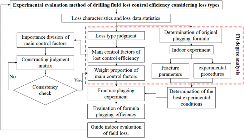
FIGURE 1. Flow chart of the experimental evaluation method for the drilling fluid lost control efficiency.
2.1 Judgment of the drilling fluid loss type in fractured formation
The loss types of fractured formation can be divided into induced fracture loss, fracture propagation loss, and natural fracture loss. By collecting the field engineering geological characteristic data on fractured formation and referring to the dynamic model of drilling fluid loss, the drilling fluid loss rate–time characteristic curve of the loss model is made as the characteristic layout, the data on the drilling fluid loss rate in the early stage of drilling fluid loss in the well to be determined are recorded, the drilling fluid loss rate–time curve is drawn, and the field drilling fluid loss rate–time curve is compared with the characteristic charts of different loss types to determine the drilling fluid loss types in fractured formation.
2.2 Drilling fluid lost control efficiency and main control factors
2.2.1 Analysis of the drilling fluid lost control efficiency
The effect and ability of drilling fluid lost control are comprehensively influenced by the strength, efficiency, and compactness of the fracture plugging zone. Commonly used indicators to characterize the effect and ability of drilling fluid lost control include the pressure bearing capacity, sealing time, loss amount, and loss rate, but there is no uniform standard and requirement for the application of evaluation indicators at present. These conditions lead to differences in the evaluation results of indoor experiments. In this paper, the plugging strength, plugging efficiency, and plugging compactness of the fractured plugging zone are comprehensively considered; the control efficiency of the drilling fluid loss in fractured formation is determined by the three factors; and the plugging strength, plugging efficiency, and plugging compactness are measured by the pressure bearing capacity, initial loss, and cumulative loss. The strength of the bearing capacity is a comprehensive reflection of the strength and structural stability of a fracture sealing zone. The strength of the fracture sealing zone can be characterized by measuring the strength of bearing capacity [33]. Bearing capacity refers to the difference between the corresponding wellbore liquid column pressure and formation pressure when the fracture sealing zone is destroyed. The greater the bearing capacity, the stronger the resistance of the fracture sealing zone to external forces and the more stable the structure. The initial loss reflects the formation efficiency of the fracture sealing zone, that is, the sealing efficiency. Initial loss refers to the loss of drilling fluid before the formation of the fracture sealing zone after the plugging material enters the fracture, which is characterized by the loss 1 min before the formation of the sealing zone. The smaller the initial loss is, the shorter the time it takes for the lost circulation material (LCM) to bridge and form the fracture sealing zone. The cumulative loss is a comprehensive reflection of the structural compactness of the fracture sealing zone. The denser the fracture plugging zone structure, the less drilling fluid will be lost. Cumulative loss refers to the loss of drilling fluid from the time the LCM enters the fracture to the time when the fracture plugging zone is destroyed. The smaller the cumulative loss, the denser the structure of the fracture sealing zone.
2.2.2 Controlling factors of the drilling fluid lost control efficiency
The main control factors of the drilling fluid lost control efficiency are different with different loss types, and the influence of plugging strength, plugging efficiency, and plugging compactness on the drilling fluid lost control efficiency is different, which makes the pressure bearing capacity, initial loss, and cumulative loss of the plugging zone have different weights in the comprehensive evaluation of the drilling fluid lost control efficiency.
Loss occurs when the working fluid density is very high for a low-pressure formation. The longer the fracture extends, the harder it is to plug. In addition, the more drilling fluid leaks, the harder it is to plug. Fluid lost control should include both prevention treatment and plugging treatment. The fluid lost control should be fast and efficient to avoid formation failure and further extension of fractures. The plugging effect depends on the fracture restart pressure and propagation pressure after the lost circulation control. For induced fracture loss, plugging fracture in time is the key to improving the plugging efficiency and drilling fluid lost control efficiency.
Fracture propagation type loss means the condition under a comprehensive influence of positive pressure difference, temperature and seepage, fracture propagation, and the solid–liquid two-phase drilling fluid flow. The fracture extends from the original width to loss fracture width and then a fracture network. The plugging effect depends on the fracture propagation pressure and plugging zone strength. For this type, the improving drilling fluid lost control efficiency should focus on plugging operation time and plugging intensity.
Natural fracture type loss refers to the type that the conventional plugging technology can successfully plug the fracture, which is often accompanied by fracture expansion and extension, making the conventional plugging method difficult to work.
The drilling fracture opening has reached the loss opening and is connected into a network. As the sealing range becomes wide, the number of weak sealing points increases. The main goal should be sealing the lost channel. The plugging effect depends on the strength and compactness of the plugging zone. Natural fracture type leakage does not require a high plugging efficiency as long as the leakage channel can be plugged to make the fracture plugging zone have a certain strength. The control efficiency of drilling fluid loss depends on whether it can be plugged and the plugging strength.
It is summarized that the main control factor of the induced fracture type lost control efficiency is the plugging efficiency. The main control factor of the fracture propagation type lost control efficiency is the plugging efficiency and plugging intensity. In addition, the main control factor of the natural fracture type lost control efficiency is plugging intensity and plugging compactness.
2.3 Analysis of weight proportion of main control factors
The main control factors of the drilling fluid lost control efficiency are different for different loss types, and the pressure bearing capacity, plugging efficiency, and plugging strength have different influences on the drilling fluid lost control efficiency. The square root method is used to calculate the relative weight of each index, and the calculation steps are as follows.
1) Based on the analysis of the drilling fluid lost control efficiency in Section 2.2, the index quantification standard is established, as shown in Table 1.
2) Calculate the geometric mean mi of all elements in each row of the judgment matrix by using the square root method, and form all the obtained mi into vector M, as shown in Formula 1.
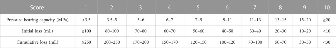
TABLE 1. Index quantification standard.
In the formula,
In the formula,
3) After calculating the geometric average of each row of elements, calculate the relative weight of each influencing factor with Formula 2.
4) Construction of the judgment matrix: Taking natural fracture loss as an example, the sealing strength and sealing compactness of the fracture sealing zone determine the control efficiency of drilling fluid loss. According to the field test data, laboratory test results, and the experience of experts and engineers, the importance of the main control factors is divided and the judgment matrix of the drilling fluid lost control efficiency is constructed [34], as shown in Table 2.
5) Consistency test: In order to ensure the validity of the judgment matrix, it is necessary to test the consistency of the evaluation results of the judgment matrix (as shown in Formulas 3, 4).
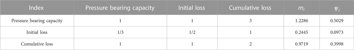
TABLE 2. Judgement matrix of the drilling fluid lost control efficiency.
RI—— the average random consistency index;
CI― the consistency coefficient, which is related to the order n and the maximum characteristic root of the matrix;
λmax― the maximum eigenvalue of the judgment matrix;
n― the order of the judgment matrix.
The consistency test results of the judgment matrix show that the evaluation system of the drilling fluid lost control efficiency for natural fractures meets the consistency standard.
Through the aforementioned steps, the weight proportion of main control factors of the drilling fluid lost control efficiency for natural fracture type loss can be obtained. Similarly, the weight proportion of main control factors of the induced fracture type and fracture propagation type drilling fluid lost control efficiency can be obtained, which is convenient for the analysis and calculation of subsequent experimental results. One decimal point is reserved. The results are shown in Table 3.
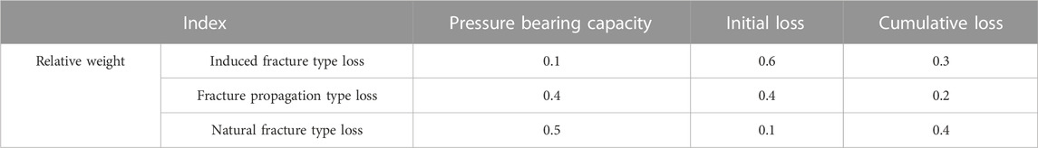
TABLE 3. Weight proportion of main control factors of different types of the drilling fluid lost control efficiency.
2.4 Fit analysis method of the lost control efficiency
There will be deviations between the indoor experiment results and the field application results. In order to further make the indoor experiment fit with the field, an analysis method of the lost control efficiency fit degree is proposed (as shown in Table 4). In the laboratory, the fracture plugging simulation experiment is carried out by different evaluation methods using the formula of the plugging slurry used in the field, including different fracture module parameters (the fracture module height, fracture module inclination angle, and fracture surface roughness) and different experimental steps (pressurization mode, single pressure increase, and pressure stabilization time). Differences between the indoor and field lost control results upon the pressure bearing capacity, initial loss, and cumulative loss are weighted in each loss type, according to the results shown in Table 4. In addition, the fit degree of this drilling fluid lost control efficiency evaluation method on each loss type is analyzed through the formula in Table 4. The grading of the evaluation results of the drilling fluid lost control efficiency is classified as “very good,” “good,” “general,” “poor,” and “very poor,” according to the aforementioned values 90%, 80%–90%, 70%–80%, 60%–70%, and less than 60%, respectively.
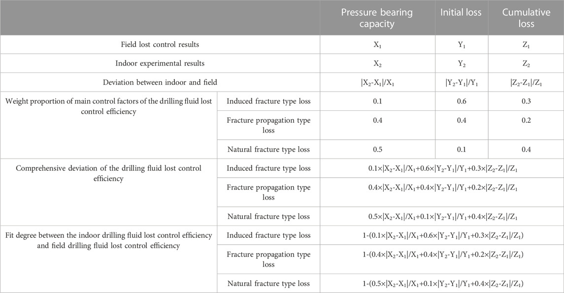
TABLE 4. Fit analysis method of the indoor and field drilling fluid lost control efficiency.
2.5 Evaluation of the lost control ability of the plugging formula under different loss types
Since the best experimental conditions are determined, fracture plugging experiments should be carried out for further analysis. A comprehensive score of different loss plugging formulas can be calculated by the evaluation method shown in lines 5 to 7. Then, the leakage plugging formulas can be graded according to the lost control capability grading system. Through this method, these loss plugging slurry formulas are classified as “very good,” “good,” “general,” “poor,” and “very poor,” according to the aforementioned values 9.5, 8–9.5, 6.5–8, 5–6.5, and less than 5, respectively.
2.6 Laboratory evaluation experiment of the drilling fluid lost control efficiency
In order to establish the experimental evaluation method of the drilling fluid lost control efficiency, it is necessary to determine the best laboratory experimental conditions for the efficiency evaluation experiment of the plugging formula. It is necessary to adopt the original plugging formula used in the field and use different evaluation methods to compare the indoor and field drilling fluid lost control efficiency. Taking Well A in Block K of the Tarim Basin as an example, the results of well lost control show that the initial loss is 14.0 mL, the cumulative loss is 41.0 mL, and the pressure bearing capacity is 13.5 MPa, which successfully blocks the fracture. The field data analysis shows that the lost circulation interval of Well A is mainly induced fracture loss, and the maximum particle size in the lost circulation formula is basically less than 3 mm. The particle size distribution range of bridging material in the formula is 1.64–2.96 mm, and the particle size distribution range of filling material is 0.17–2.12 mm. The fracture type corresponds to the indoor 3–1 mm wedge fracture.
2.6.1 Laboratory sample
In the lost circulation case of well A, the formula for successful lost control is “water-based drilling fluid+3% LCM-S2+5% LCM-F1+5% LCM-F2+0.5% LCM-X1.” According to the formula of the basic plugging slurry on site, the LCMs used in indoor experiments are selected. In the experiment, 3D wedge-shaped plungers with the same fracture width (3 mm–1 mm) and different fracture heights, fracture inclination (defined as the ratio of the fracture height to fracture length in this paper), and fracture surface roughness were selected as experimental plungers to study the effects of fracture height, fracture inclination, and fracture surface roughness on the drilling fluid lost control efficiency. The parameters of each plunger are shown in Table 5.
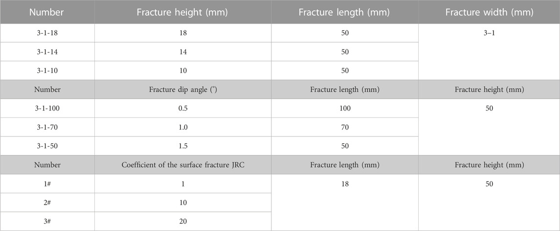
TABLE 5. Related parameters of each plunger.
To study the influence of experimental steps on the control efficiency of drilling fluid loss, the experimental plungers all use unified plungers. On the premise that the fracture width is fixed at 3–1 mm, the most commonly used 3D printing wedge plunger with the fracture height of 18 mm, the dip angle of 1.5, and the JRC coefficient of the fracture surface of 1 is selected.
2.6.2 Laboratory installation
An indoor fracture plugging simulation experiment was conducted with a self-made portable damage assessment instrument [31]. When exploring the influence of experimental steps on the control efficiency of drilling fluid loss, different experimental steps are set. The preliminary preparation work and the experimental process remain unchanged. In addition, the pressurization mode, the single pressure increase, and the pressure stabilization time will be changed. Table 6 represents the specific scheme.
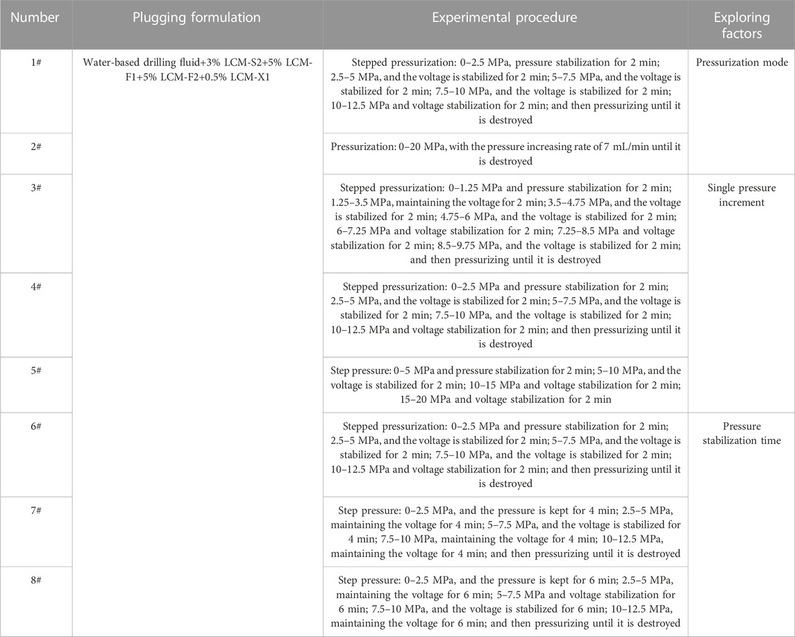
TABLE 6. Experimental scheme of the influence of experimental steps on the drilling fluid lost control efficiency.
3 Results and discussion
The loss control results of Well A in Block K were studied as an example, and the method was used to evaluate the induced fracture loss. In addition, the weighting proportion of main fluid lost control factors and the experimental steps were reconfirmed.
3.1 Effect of fracture parameters on the drilling fluid lost control efficiency
3.1.1 Effect of fracture height
The experimental results of the influence of the fracture height on the drilling fluid leakage control efficiency are shown in Figure 2. Plungers with experimental heights of 18 mm, 14 mm, and 10 mm were selected. According to the analysis method of the indoor and on-site drilling fluid lost control efficiency fit shown in Table 4, the calculation results of the indoor plunger with different fracture heights and the on-site drilling fluid lost control efficiency fit are obtained.
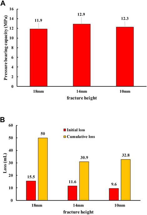
FIGURE 2. Experimental results of different height fracture modules: (A) pressure bearing capacity of fracture modules with different heights and (B) loss of different height fracture modules.
The results show that the lost control efficiency of the plunger drilling fluid with a fracture height of 18 mm is in the highest agreement with the field results, and the evaluation result of the drilling fluid lost control efficiency is “good.” The lost control efficiency of the plunger drilling fluid with a fracture height of 10 mm has the lowest agreement with the field results, and the evaluation result of the drilling fluid lost control efficiency is “average.” For the plunger with a fracture height of 18 mm, the fracture height: fracture entrance width is 6: 1. For a plunger with a fracture height of 10 mm, the fracture height: fracture entrance width is about 3: 1. Therefore, when the ratio of the fracture height to fracture entrance width is larger, the coincidence degree of indoor and field drilling fluid lost control efficiency is higher. Combined with this experimental data, when the fracture height: fracture entrance width is 6: 1, the evaluation result of the drilling fluid lost control efficiency is the best.
3.1.2 Effect of fracture dip angles
The experimental results of the influence of fracture inclination on the drilling fluid lost control efficiency are shown in Figure 3. Select plungers with experimental inclination angles of 0.5, 1.0, and 1.5. According to the analysis method of indoor and field drilling fluid lost control effectiveness, the calculation results of indoor plungers with different inclination angles and field drilling fluid lost control effectiveness are obtained.
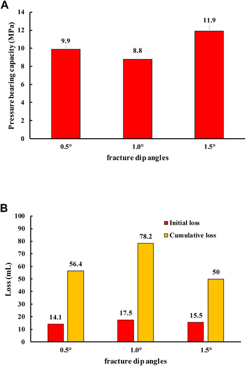
FIGURE 3. Experimental results of fracture modules with different dip angles: (A) pressure bearing capacity of fracture modules with different dip angles and (B) loss of different dip angle fracture modules.
The results show that the lost control efficiency of plunger drilling fluid with fracture inclination angles of 0.5 and 1.5 is higher than that of the field, and the difference between them is very small. The evaluation results of both the drilling fluid lost control efficiency are “good.” However, the lost control efficiency of plunger drilling fluid with a fracture inclination of 1.0 is the lowest, and the evaluation result is “poor,” which is close to “very poor.” The length of plunger fracture with a crack inclination of 0.5 is 100 mm. The length of plunger fracture with a fracture inclination of 1.5 is 50 mm. When the fracture dip angle is greater than 1 and close to 1.5 or less than 1 and close to 0.5, the indoor and on-site drilling fluid lost control efficiency fits well. Combined with the experimental data, the fracture dip angle ranges from 0.5 to 1.5, and the evaluation effect of the drilling fluid lost control efficiency is the worst when the dip angle is 1. Therefore, when evaluating the drilling fluid lost control efficiency, the value of the fracture dip angle should deviate from 1 as much as possible.
3.1.3 Effect of fracture surface roughness
The experimental results of the influence of the fracture JRC coefficient on the drilling fluid lost control efficiency are shown in Figure 4. The plunger with the JRC coefficient of the fracture surface of 1, 10, and 20 mm was selected in the experiment. According to the analysis method of indoor and field drilling fluid lost control effectiveness, the calculation results of the indoor JRC coefficient plunger and field drilling fluid lost control effectiveness are obtained.
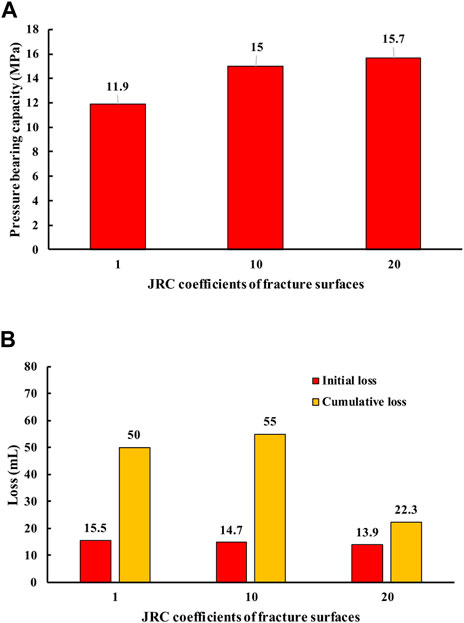
FIGURE 4. Experimental results of fracture modules with different JRC coefficients: (A) bearing capacity of fracture modules with different JRC coefficients of fracture surfaces and (B) loss of different JRC coefficient fracture modules.
The results show that the lost control efficiency of the plunger drilling fluid with the JRC coefficient of the fracture surface of 20 is the highest in accordance with the field, and the evaluation result of the drilling fluid lost control efficiency is “good.” The lost control efficiency of plunger drilling fluid with a fracture JRC coefficient of 1 is the lowest, and there is an obvious linear relationship between the lost control efficiency of indoor and field drilling fluid and the roughness of the fracture surface. In a certain range, the coarser the fracture surface is, the greater the JRC coefficient of the fracture surface is, and the higher the lost control efficiency of indoor and field drilling fluid is.
3.2 Effect of experimental steps on the drilling fluid lost control efficiency
3.2.1 Effect of the pressurization mode
The experimental results of the influence of different pressurization methods on the drilling fluid lost control efficiency are shown in Figure 5. The pressurization methods selected in the experiment are step pressurization and continuous pressurization. The calculation results of the coincidence degree between different pressurization methods and on-site drilling fluid lost control efficiency are obtained.
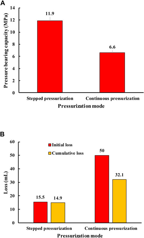
FIGURE 5. Experimental results of different pressurization modes: (A) bearing capacity of fracture modules with different pressurization modes and (B) loss of different pressurization modes.
The results show that there is no obvious difference between the indoor and field drilling fluid lost control efficiency in two different pressurization methods, and the evaluation results of the drilling fluid lost control efficiency are all “good.” According to the analysis, stepped pressurization gradually pushes the plugging material into the fracture by pressurization–pressure stabilization–pressurization, while continuous pressurization pumps the displacement fluid at a constant rate. No matter which pressurization method is used, it has little influence on the initial loss, and the plugging efficiency has no obvious change. For the induced fracture loss, the plugging efficiency accounts for the largest proportion of the drilling fluid lost control efficiency, which is 0.6. Therefore, there is no obvious difference between the drilling fluid lost control efficiency of the two different pressurization methods and the on-site fit degree.
3.2.2 Effect of single pressurization increase
The experimental results of the influence of different single pressurization increases on the drilling fluid lost control efficiency are shown in Figure 6. Different single pressure increases of 1.25 MPa, 2.5 MPa, and 5.0 MPa were selected in the experiment. Determine the calculation results of the coincidence degree between different single pressure increases and the on-site drilling fluid lost control efficiency.
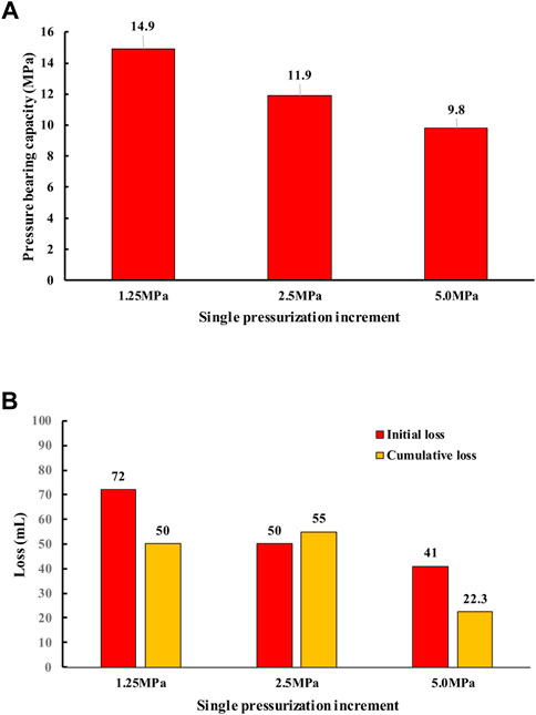
FIGURE 6. Experimental results of different single pressurization increases: (A) bearing capacity of fracture modules with different single pressurization increases and (B) loss of different single pressurization increases.
The results show that when the single pressure increase is 5 MPa, the drilling fluid lost control efficiency is the highest in accordance with the field, and the evaluation result of the drilling fluid lost control efficiency is “good.” When the single pressure increase is 1.25 MPa, the drilling fluid lost control efficiency is the lowest in correspondence with the field, and the evaluation result of the drilling fluid lost control efficiency is “poor.” Moreover, there is an obvious linear relationship between the coincidence degree of the drilling fluid lost control efficiency in the field and indoor and the single pressure increase. In a certain range, the greater the single pressure increase, the higher the coincidence degree.
The main control factor of the lost control efficiency for induced fracturing drilling fluid is the plugging efficiency, which is characterized by the initial lost in the experiment. The higher the plugging efficiency, the less time it takes to form an effective plugging zone and the lower the initial loss. When the single pressure increase is different, with the increase of the single pressure increase, the time required for the LCM to enter the fracture to form a plugging zone is less, the plugging efficiency is higher, and the initial loss is less, thus improving the drilling fluid lost control efficiency. When the single pressure increase is small and the indoor drilling fluid lost control efficiency is poor, with the increase of the single pressure increase, the lost control becomes better and the coincidence degree of the indoor and field drilling fluid lost control efficiency is improved.
3.2.3 Effect of pressure stabilization time
The experimental results of the influence of different pressure stabilization time on the drilling fluid lost control efficiency are shown in Figure 7. In the experiment, the different pressure stabilization time is 2 min, 4 min, and 6 min. Determine the calculation results of the coincidence degree between different pressure stabilization time and the on-site drilling fluid lost control efficiency.
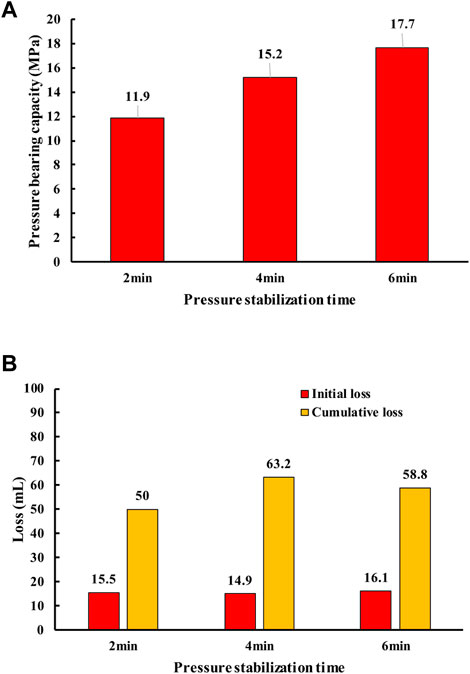
FIGURE 7. Experimental results of different pressure stabilization time: (A) bearing capacity of fracture modules with different pressure stabilization time and (B) loss of different pressure stabilization time.
The results show that when the pressure stabilization time is 2 min, the coincidence degree of the indoor and field drilling fluid lost control efficiency is the highest and the evaluation result of the drilling fluid lost control efficiency is “good.” However, when the pressure stabilization time is 6 min, the fitting degree is the lowest and the evaluation result of the drilling fluid lost control efficiency is “average.” In a certain range, the coincidence degree of the indoor and field drilling fluid lost control efficiency is negatively correlated with the pressure stability time.
According to the above three series of analysis and experimental results, it can be seen that the evaluation method of out-of-control efficiency of experimental drilling fluid induces fracture loss. When the fracture height: fracture entrance width is 6: 1, the degree of fracture inclination deviation of 1° is high and the fracture surface is rough; then, the indoor and field drilling fluid lost control efficiency fits well. For induced fracture loss, a perfect experimental evaluation method of the drilling fluid lost control efficiency will be supported by this result. As for the evaluation of experimental steps, in the pressurization mode, there is no significant difference between the indoor and field drilling fluid lost control efficiency. In addition, the drilling fluid lost control efficiency is less affected by the evaluation of the pressurization mode. However, the choice of the single pressure increase is more suitable for the evaluation of the drilling fluid lost control efficiency with a higher single pressure increase, and the evaluation results are more consistent with the field. Regarding the selection of pressure stabilization time, when the pressure stabilization time exceeds 1 min, the shorter the pressure stabilization time is and the higher the coincidence degree of the indoor and field drilling fluid lost control efficiency is. Aiming at the induced fracture loss, the perfect experimental evaluation method of the drilling fluid lost control efficiency will be supported by the aforementioned comprehensive analysis results.
3.3 Experimental evaluation method and application strategy of the drilling fluid lost control efficiency
Combined with the experimental analysis results of the influence of fracture module parameters and experimental steps on the drilling fluid lost control efficiency, as shown in Section 3.1 and Section 3.2, an experimental evaluation method of the drilling fluid lost control efficiency for the induced fracture loss is established.
3.3.1 Experimental method of the drilling fluid lost control efficiency considering various loss types
For induced fracture loss, the best fracture height, fracture dip angle, fracture surface roughness, the best pressurization mode, single pressure increase, and pressure stabilization time are defined so as to evaluate the drilling fluid lost control efficiency systematically. At the same time, experiments have been carried out on fracture propagation type loss and natural fracture type loss, and the experimental conditions, as shown in Table 7, have been established.
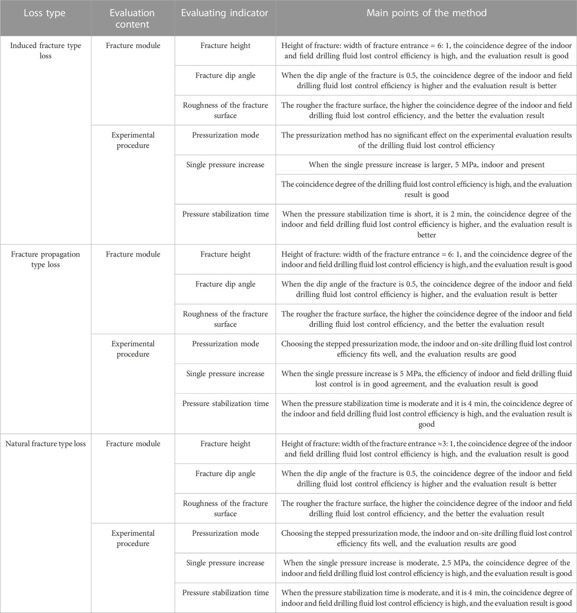
TABLE 7. Experimental scheme of the influence of experimental steps on the drilling fluid lost control efficiency.
3.3.2 Application strategy
Considering that more than one type of drilling fluid loss can present in some cases, it is necessary to determine the loss types and analyze proportion of each loss type so as to determine the major and secondary loss types. The ideas are as follows:
(1) Determine the loss type. Determine the primary and secondary loss types, and analyze the weight proportion of different loss types by AHP; refer to the analysis method of weight proportion of evaluation indicators in Section 2.4, analyze the weight proportion of different loss types, and determine that the proportion of induced fracture loss, fracture propagation loss, and natural fracture loss are M, N, and O (if there are three loss types at the same time), respectively, and if there are two loss types at the same time, determine the weight proportion of M and N, respectively (M, N, O are all ∈ [0,1]).
(2) Use the experimental evaluation method of the drilling fluid lost control efficiency aiming at different loss types; after the main loss types are determined, the evaluation method corresponding to the main loss types is selected to evaluate the drilling fluid lost control efficiency through Table 7. If the main loss type is induced fracture type, the drilling fluid lost control efficiency will be evaluated according to induced fracture type loss, and the remaining cases are the same.
(3) Make a comprehensive evaluation on the lost control ability of the plugging slurry formula and give the grading results.
According to step 1), among the loss types of fractured formation, the determined proportions of induced fracture type loss, fracture propagation type loss, and natural fracture type loss are M, N, and O (if there are three types of leakage at the same time), respectively. Determine the comprehensive score of the lost control ability of plugging slurry.
where x, y, and z are the specific scores of bearing capacity, initial loss, and cumulative loss in the lost control results, respectively, which are obtained by combining the specific values of the three indicators with Table 1.
For the final R value, refer to Table 8 to determine the grading result of the lost control ability of the plugging slurry formula.
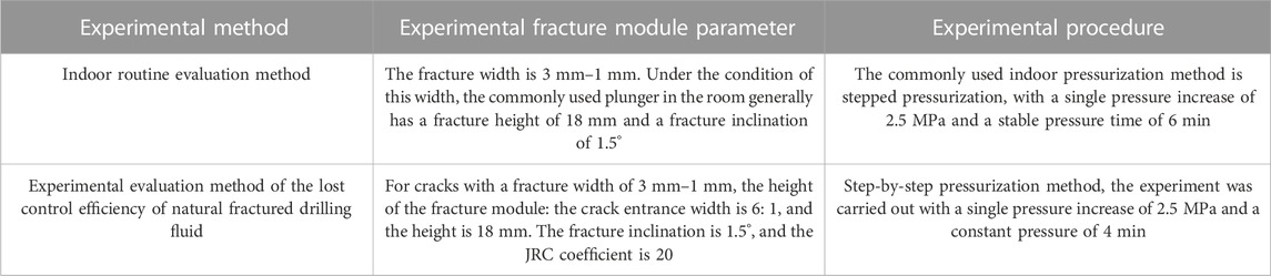
TABLE 8. Indoor experiment evaluation method.
4 Field test
Well D is an evaluation well located in Block K of the Tarim Basin, and it has developed micro-fractures. When drilling to the well depth of 5694–5819 m, loss occurred. The on-site plugging slurry formula was oil-based drilling fluid (1.88) +4%NTS-M (medium coarse) +7% NTS-S (type II, medium coarse) +5% NTS (type I, coarse) +2%GYD-coarse +3%GYD-medium coarse +5%GYD-fine. Carry out indoor experiments with the same formula.
According to the evaluation method proposed in this paper, the coincidence degree with the on-site drilling fluid lost control efficiency exceeds 90%, and the evaluation result is rated as “very good.” The indoor conventional evaluation method, which is just over 80% consistent with the on-site drilling fluid lost control efficiency, has a rating between “good” and " general.” Two different indoor evaluation methods are used to evaluate the effectiveness of drilling fluid lost control. The evaluation method proposed in this paper is closer to the field lost control result, and the evaluation result of drilling fluid lost control effectiveness is better.
When the conventional laboratory experiment method is adopted, the evaluation method of the lost control ability of the natural fracture type loss plugging slurry formula is adopted, where the value of X can be determined as 2 by referring to Table 1 with the pressure bearing capacity of 4.6 MPa, and similarly, Y and Z can be determined as 8 and 7, respectively. R = 4.6 can be obtained, and the result is graded as “very poor,” according to the lost control ability grading system of the loss slurry formula.
When the method proposed in this paper is adopted, according to the judgment result of loss type, R = 0.5 × 3 + 0.1 × 7 + 0.4 × 5 = 4.2 can be obtained, and the result is classified as “poor,” according to the classification system of the lost control ability of the slurry loss formula. The evaluation method proposed in this paper is the same as the conventional indoor evaluation method in grading the evaluation results of the same plugging slurry formula, which verifies the feasibility of the evaluation method proposed in this paper. In addition, the evaluation method can realize the reasonable evaluation of on-site lost control, and the efficiency of indoor and on-site drilling fluid lost control is in high agreement with good evaluation results. This method can effectively guide on-site lost control evaluation, such as oil and gas fractured reservoirs and EGS of deep hot-dry rock.
5 Conclusion
In this paper, the control efficiency of drilling fluid loss is analyzed and the relative weight ratio of main control factors is defined. Based on the correspondence between the indoor and field drilling fluid lost control efficiency, the reasonable fracture module parameters and experimental steps for indoor evaluation of the drilling fluid lost control efficiency are put forward, and the experimental evaluation methods for the drilling fluid lost control efficiency in fractured formations with different loss types are established. The main achievements and understandings are as follows
(1) The control efficiency of drilling fluid loss is the comprehensive embodiment of the strength, sealing efficiency, and sealing compactness of the fracture sealing zone formed when controlling the loss. These three important indexes are characterized by the pressure bearing capacity, initial loss, and cumulative loss in the laboratory.
(2) The main control factors of the drilling fluid lost control efficiency of different loss types and the weight ratio of main control factors are defined. For induced fracture loss, the best fracture height, fracture dip angle, fracture surface roughness, the best pressurization mode, single pressure increase, and pressure stabilization time are defined so as to evaluate the drilling fluid lost control efficiency systematically. Make a comprehensive evaluation on the lost control ability of the plugging slurry formula and give the grading results. A method for judging drilling fluid loss types in fractured formations is proposed based on the relationship between the loss rate and time.
(3) The experimental evaluation method of the drilling fluid lost control efficiency considering various loss types is established. According to the analysis method of the experimental results of the drilling fluid lost control efficiency, the indoor evaluation method with the highest coincidence degree with the on-site drilling fluid lost control efficiency is obtained, including the height of the fracture module with the highest coincidence degree, fracture inclination, fracture surface roughness, pressurization mode, single pressure increase, and pressure stabilization time. Considering the simultaneous existence of multiple losses, a comprehensive evaluation and grading method of the lost control ability of the plugging slurry considering multiple loss is put forward. Through the aforementioned method, the field lost control evaluation can be effectively guided, which is of great significance to drilling fluid lost control and reservoir protection.
Data availability statement
The original contributions presented in the study are included in the article/Supplementary Material; further inquiries can be directed to the corresponding authors.
Author contributions
JZ comprehensively contributed to the work of the manuscript, including the design of the study, organized the data, and performed the statistical analysis. YK and CX mainly contributed to the design of the study. XY and CL mainly contributed to the organization of the database. All authors contributed to manuscript revision, and read and approved the submitted version.
Acknowledgments
The authors would like to thank the support of the National Natural Science Foundation of China (52004233) and the support of the Natural Science Foundation of Sichuan Province (23NSFSC1596). Finally, the authors would like to thank the paper reviewers for their valuable comments and suggestions. They gratefully acknowledge the financial support from the China Postdoctoral Science Foundation (Grant No. 2022M723501).
Conflict of interest
JZ and YD were employed by the company China Zhenhua Oil Co., Ltd.
The remaining authors declare that the research was conducted in the absence of any commercial or financial relationships that could be construed as a potential conflict of interest.
Publisher’s note
All claims expressed in this article are solely those of the authors and do not necessarily represent those of their affiliated organizations, or those of the publisher, the editors, and the reviewers. Any product that may be evaluated in this article, or claim that may be made by its manufacturer, is not guaranteed or endorsed by the publisher.
References
1. Klungtvedt KR, Khalifeh M, Saasen A, Berglind B, Vasshus KJ. Preventing drilling fluid induced reservoir formation damage. In: SPE/IADC Middle East Drilling Technology Conference and Exhibition; Abu Dhabi, UAE (2021).
2. Lavrov A. Lost circulation: Mechanisms and solutions. Gulf Professional Publishing, Elsevier (2016).
3. Windarto GAY, Sukarno P, Soewono E. Modelling of formation damage due to mud filtrate invasion in a radial flowsystem. J Pet Sci Eng (2012) 100:99–105. doi:10.1016/j.petrol.2012.11.003
4. Sun JS, Bai YR, Cheng RC, Lv KH, Liu F, Feng J, et al. Research progress and prospect of plugging technologies for fractured formation with severe lost circulation. Pet Exploration Dev (2021) 48:732–43. doi:10.1016/s1876-3804(21)60059-9
6. Wang H, Sweatman R, Engelman R, Deeg W, Whitfill D, Soliman M, et al. Best practice in understanding and managing lost circulation challenges. SPE Drilling and Completion (2008) 23:168–75. doi:10.2118/95895-pa
7. Mortadha A, Mohammed F, Runar N. Updated criterion to select particle size distribution of lost circulation materials for an effective fracture sealing. J Pet Sci Eng (2017) 149:641–8.
8. Beda G, Carugo C. Mud microloss analysis while drilling improves fractured- reservoir evaluation. J Pet Tech (2002) 54:0149–2136.
9. Kang YL, Xu CY, Tang L, Li S. Constructing a tough shield around the wellbore: Theory and method for lost-circulation control. Pet Exploration Dev (2014) 41:520–7. doi:10.1016/s1876-3804(14)60061-6
10. Zeng YJ, Li DQ, Yang CH. Leakage prevention and control in fractured formations. Chin J Rock Mech Eng (2016) 35:2054–61.
11. Xu CY, Kang YL, You LJ, You Z. Lost-circulation control for formation-damage prevention in naturally fractured reservoir: Mathematical model and experimental study: Mathematical model and experimental study. SPE J (2017) 22:1654–70. doi:10.2118/182266-pa
12. Ivan CD, Bruton JR, Thiercelin M, Bedel JP Making a case for rethinking lost circulation treatments in induced fractures. In: SPE Annual Technical Conference and Exhibition. San Antonio, Texas (2002).
13. He YC, Han TF, Zhao JG. Development of high-temperature visual plugging instrument. Equipment Geotechnical Eng (2017) 18:3–5.
14. Duan MX, Zhang XF, Zhang QM. BDY-1 portable plugging device for drilling fluid. Driuing Fluid and Completion Fluld (2002) 19:30–1.
15. Li J. Study on improvement of experimental technology of drilling fluid plugging evaluation. BeiJing: China University of Petroleum (2010).
16. Yu WC, Su CM, Huang XR, Zhang CY. Development of high temperature high pressure (HTHP) dynamic sealing evaluating system. J oil gas Technol (2000) 28:13–4.
17. Albattat R, Hoteit H. A semi-analytical approach to model drilling fluid leakage into fractured formation. Rheologica Acta (2021) 60(6):353–70. doi:10.1007/s00397-021-01275-3
18. Al-saba MT, Nygaard R, Saasen A, Nes OM. Lost circulation materials capability of sealing wide fractures. In: SPE Deepwater Drilling and Completions Conference. Society of Petroleum Engineers (2014).
19. Al-saba MT, Nygaard R, Saasen A, Nes OM. Laboratory evaluation of sealing wide fractures using conventional lost circulation materials. In: SPE annual technical conference and exhibition. Society of Petroleum Engineers (2014).
20. Wang G, Cao C, Pu X, Zhao Z. Experimental investigation on plugging behavior of granular lost circulation materials in fractured thief zone. Particulate Sci Tech (2016) 34:392–6. doi:10.1080/02726351.2015.1089963
21. Zhong H, Shen G, Yang P, Qiu Z, Jin J, Xing X. Mitigation of lost circulation in oil-based drilling fluids using oil absorbent polymers. Materials (2018) 11:2020. doi:10.3390/ma11102020
22. Xu C, Kang Y, Chen F, You Z. Analytical model of plugging zone strength for drill-in fluid loss control and formation damage prevention in fractured tight reservoir. J Pet Sci Eng (2017) 149:686–700. doi:10.1016/j.petrol.2016.10.069
23. Kang YL, Zhang JY, Xu CY, You LJ, L C. The effect of geometrical morphology of rigid lost circulation materialon its retention behavior in fractures. Pet Drilling Tech (2018) 46:26–34.
24. Majidi R, Miska SZ, Ahmed R, Yu M, Thompson LG. Radial flow of yield-power-law fluids: Numerical analysis, experimental study and the application for drilling fluid losses in fractured formations. J Petrol Sci Eng (2010) 70(3–4):334–43. doi:10.1016/j.petrol.2009.12.005
25. Qiu ZS, Bao D, Liu YJ, Chen J, Chen X Microcosmic mechanism of fracture-plugging instability and experimental study on pressure bearing and tight plugging. Acta Petrolei Sinica (2018) 39:587–96.
26. Mostafavi V, Hareland G, Belayneh M, Aadnoy BS. Experimental and mechanistic modeling of fracture sealing resistance with respect to fluid and fracture properties. U.S. symposium on rock mechanics. American rock mechanics association (2011).
27. Nasiri A, Ghaffarkhah A, Dijvejin ZA, Mostofi M, Moraveji MK. Bridging performance of new eco-friendly lost circulation materials. Pet Exploration Dev (2018) 45:1154–65. doi:10.1016/s1876-3804(18)30119-8
28. Xu CY, Yan XP, Kang YL, You LJ, You ZJ, Zhang H, et al. Friction coefficient: A significant parameter for lost circulation control and material selection in naturally fractured reservoir. Energy (2019) 174:1012–25. doi:10.1016/j.energy.2019.03.017
29. Grant P, Lassus L, Savari S, Whitfill DL. Size degradation studies of lost circulation materials in a flow loop. In: IADC/SPE Drilling Conference and Exhibition; Fort Worth, Texas, USA (2016).
30. Omid R, Ali KV, Eric VO, Munir A, Sudarshan G. Optimum particle size distribution design for lost circulation control and wellbore strengthening. J Nat Gas Sci Eng (2016) 35:836–50.
31. Xu CY, Zhang HL, Kang YL, Zhang JY, Bai YR, Zhang J, et al. Physical plugging of lost circulation fractures at microscopic level. Fuel (2022) 317:123477. doi:10.1016/j.fuel.2022.123477
32. Albattat R, AlSinan M, Kwak H, Hoteit H. Modeling lost-circulation in natural fractures using semi-analytical solutions and type-curves. J Pet Sci Eng (2022) 216(2022):110770. doi:10.1016/j.petrol.2022.110770
33. Lavrov A. From fracture gradient to spectrum of lost-circulation pressures: A paradigm shift. Energ Proced (2017) 114:3185–92. doi:10.1016/j.egypro.2017.03.1447
Keywords: lost circulation, fractured reservoir, loss control, reservoir protection, lost circulation formula, evaluation method
Citation: Zhang J, Kang Y, Deng Y, Xu C, Yan X, Lin C and Cui X (2023) An experimental evaluation method of drilling fluid lost control efficiency considering loss types. Front. Phys. 11:1079345. doi: 10.3389/fphy.2023.1079345
Received: 25 October 2022; Accepted: 18 April 2023;
Published: 06 July 2023.
Edited by:
G. Cheraghian, Technical University of Braunschweig, GermanyCopyright © 2023 Zhang, Kang, Deng, Xu, Yan, Lin and Cui. This is an open-access article distributed under the terms of the Creative Commons Attribution License (CC BY). The use, distribution or reproduction in other forums is permitted, provided the original author(s) and the copyright owner(s) are credited and that the original publication in this journal is cited, in accordance with accepted academic practice. No use, distribution or reproduction is permitted which does not comply with these terms.
*Correspondence: Yili Kang, Q1dDVF9GRENAMTYzLmNvbQ==; Jingyi Zhang, c3dwdXpqeUAxNjMuY29t