- 1Hubei Key Laboratory of Modern Manufacturing Quality Engineering, Hubei University of Technology, Wuhan, China
- 2China Nuclear Power Operation Technology Co., Ltd., Wuhan, China
- 3Huazhong University of Science and Technology, Wuhan, China
The flexible eddy current array sensor owns the advantages of high sensitivity and strong adaptability, but the results are always affected by the curvature radius of complex curved surfaces. The relationship between the curvature radius of the curved surface and detection signals for surface-breaking cracks is mainly discussed. The change of magnetic field caused by the curved surface in the present eddy current testing is specially pointed out, which manifest themselves in the compression or enhancement of the testing signal in its peak value and the baseline drifts. Simulation and experimental results indicate that the concave surface weakens the signal, while the convex surface enhances the signal. The signal amplitude decreases with the decrease in the curvature radius for the concave surface, while it is the opposite for the convex surface. Meanwhile, coil spacing significantly affects the amplitude–curvature radius curve. Furthermore, the fluctuation characteristic affected by the curvature radius under different coil spacing is analyzed. The discovery and results will benefit the quantitative evaluation of flexible eddy current array testing.
1 Introduction
Eddy current testing (ECT) [1, 2] is widely used in nondestructive testing of metal components [3–5], owing to its high detection sensitivity [6, 7], but the detection signals of ECT are always affected by the changes in the curvature of the test piece with complex surfaces such as fillet welds, gears, and steam turbine blades, which will seriously affect the quantization accuracy of the defect. Compared with conventional eddy current testing [8], flexible eddy current array (FECA) testing can ensure constant lift-off under effective coverage and plays an important role in the surface defect detection of complex components [9]. The FECA uses rubber or other flexible materials to support, protect, and bend itself [10]. The FECA probe commonly consists of multiple pancake coils [11]. The receiving parts of the FECA probe are used for induction coil or magnetic sensors such as Hall [12, 13], AMR [14–16], GMR [17–19], and TMR [20–24].
Many research studies focus on new FECA probe designs to improve the detection ability [25–28], but the works mentioned earlier are always conducted based on the simple and sketchy hypothesis that the surface of the workpiece is flat. In general, most of the actual objects to be detected are curved surface, variable curvature surface, and other irregular surface, leading to a complex surface state. The bendability of the FECA probe makes it widely used in the detection of specific irregular surface parts, such as steel ball [29], hollow shaft [30, 31], bolt hole [32, 33], and steel pipe [34]. The relevant research studies mainly focus on the new structural design of the probe [32–36], the parameter optimization of the array probe [37], and variable excitation methods [38, 39]. Huayu Zhang et al. used a FECA sensor arranged in a “concave” shape to detect the steel ball [29]. Peiyuan Li et al. designed a rosette eddy current array sensor to detect cracks in aluminum alloy bolt holes [32]. Miguel A. Machado et al. designed a trapezoidal coil array wound on the skeleton to eliminate the detection blind area of the probe [34]. Yingsong Zhao et al. designed a spiral multicoil probe, which uses coil arrangement and the signal mode to reduce the jitter noise caused by lift-off and tilt [36]. In these studies, the FECA probe maintains a specific shape in the detection process without considering the effects of shape bending, so the consistency of the detection signal will not be affected by the radius of curvature.
The most significant advantage of the FECA probe is its “flexibility” to adapt to various components with irregular surfaces, and it can change its shape because of its bendability. Ruifang Xie et al. designed a new flexible planar eddy current sensor array for microcrack in key aircraft components [40]. Michal Janovec et al. used the eddy current array to conduct nondestructive evaluation on the riveted joints of the fuselage and wing of the aircraft [41]. Weipeng Zhang et al. designed a probe to be arranged in parallel and staggered and realized the three-dimensional imaging of the surface quality of turbine blades [42]. H. Endo et al. designed a FECA testing and evaluation system for complex parts [43]. Lei Peng et al. changed the connection angle between the two receiving coils to avoid the missing detection of defects caused by symmetry in the differential probe [44]. Saibo She et al. designed an “H”-type differential flexible butterfly coil array to detect the thread defect and achieve no blind angle detection [45]. However, these studies focus more on the application aspects and ignore the influence of the shape change caused by the probe to the curved surface on the detection signal. The substrate of the FECA can be bent, while the pancake coil unit itself cannot be bent when the components with irregular curved surface are detected, resulting in a non-uniform gap between the pancake coils and the curved surface. The change in the curvature radius will change the distribution of the eddy current on the curved surface because of different non-uniform gaps, and it finally affects the spatial magnetic field and the detection signal. On the other hand, the relative position between coils will also change when the probe bends, which is difficult to ensure the consistency of defect evaluation.
In this study, the concept of the magnetic field change is briefly presented to explain the signal-changed phenomenon on the curved surface, which manifests itself in the diffusion or concentration of eddy currents in its density. In Section 2, the distribution of magnetic field on the curved surface is analyzed from the perspective of the magnetic emission. In Section 3, the 3D convex surface and concave surface are considered separately to analyze the changes of the eddy current distribution density, spatial magnetic field, and induction voltage of the receiving coil. In Section 4, an experimental investigation on concave and convex surfaces with different curvature radius is performed, and the variation curve between the signal amplitude and radius of curvature is obtained. Furthermore, the fluctuation of the curve under different coil spacing is analyzed to provide guidance for coil spacing selection. In Section 5, derived conclusions are given.
2 Mechanism
The concave surface (point D), convex surface (point A), variable curvature surface (point C), and other irregular surfaces are widely present in complex components, as shown in Figure 1A. This study focuses on revealing some variation laws and its mechanisms of eddy current testing on curved surfaces. Therefore, in order to simplify the analysis, simplified models are used to approximate the local real complex surfaces, as shown in Figure 1B.
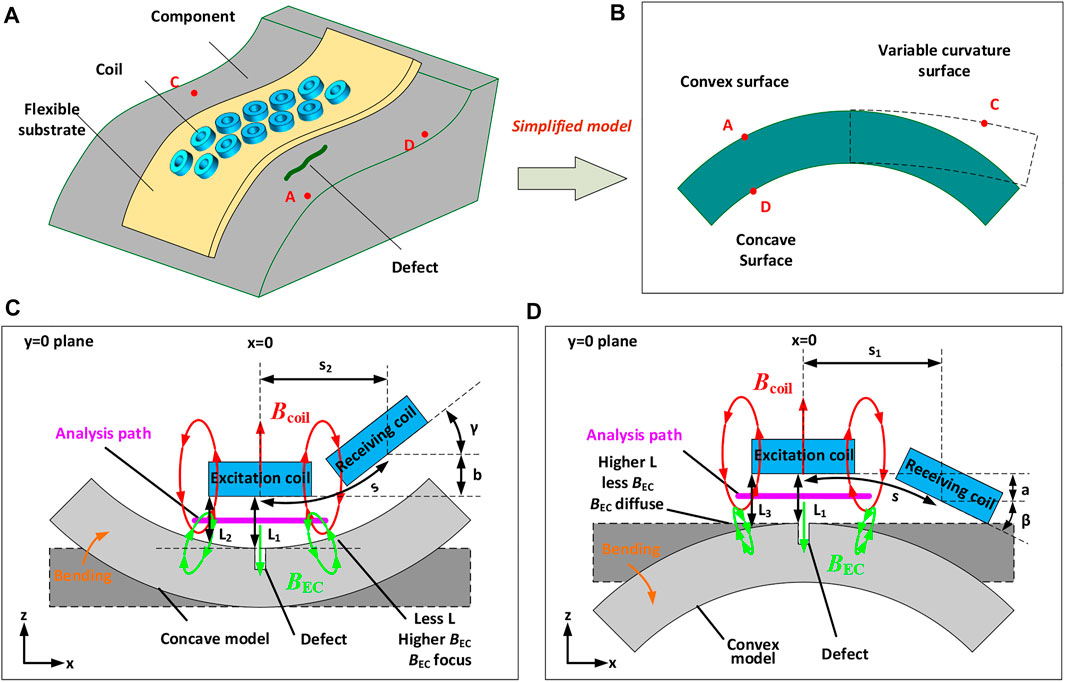
FIGURE 1. (A) Schematic diagram of the probe. (B) Schematic diagram of surface model transformation. (C) and (D) Analysis diagrams of the concave and convex models.
In order to reveal the mechanism of the electromagnetic field change caused by the radius of curvature, an independent unit of the FECA was selected for further analysis, as shown in Figures 1C,D. The axis position of the excitation coil is located at x = 0 when the coils are placed on the plane model. The lift-off between the coil and the plane is equal everywhere, denoted as
The receiving coil is placed horizontally at a distance s on the right side of the excitation coil of the plane model. The coil is placed on the flexible substrate, and the flexible substrate always fits the surface of the test piece, when the model changes from the plane surface to the concave surface, as shown in Figure 1C. The arc length of the spacing s between the excitation coil and the receiving coil will be distributed above the surface of the concave model. The receiving coil is deflected counterclockwise by γ, then shifted upward by a distance b relative to the excitation coil at the vertical height, and horizontally shifted to the left by a distance s-s2. Similarly, in the convex model shown in Figure 1D, the receiving coil is deflected clockwise by β, vertically shifted downward by distance a, and horizontally shifted to the left by a distance s-s1.
The eddy current will be generated on the surface of the test piece when the coil generates a changing magnetic field
3 Simulations
3.1 Model setup
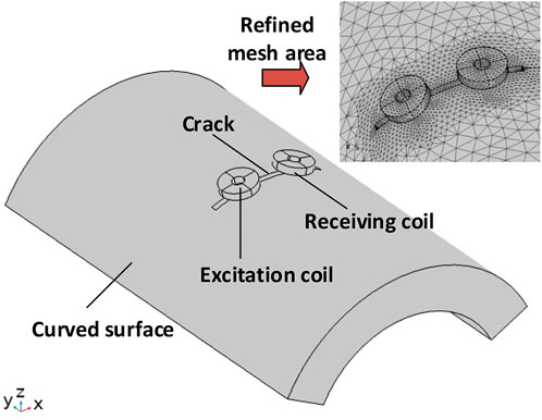
In this section, a three-dimensional FEA model is built in COMSOL Multiphysics to analyze the eddy current distribution and the corresponding testing signals of models with different curvature radii, as shown in Figure 2. Different convex and concave models are achieved by changing the radius of the model. In addition, the flat model is established separately. The finite element model consists of the air domain, excitation coil, receiving coil, and specimen. The excitation coil and receiving coil were set as copper, and the test piece is set as stainless steel. The areas of refined mesh were applied to the skin layer to enhance the computing quality, as shown in Figure 2. The relevant parameters of the model are shown in Table 1.
3.2 Eddy current distribution on different curved surfaces
Figures 3A–C shows the eddy current distribution on the concave, plane, and convex models without defect. The curvature radii of the concave model and convex model are both 5 mm. As can be seen, the eddy current distribution on three types of surfaces shows obvious differences. Specifically, the eddy current distribution of the concave model is more dispersed than that of the convex model. Compared with the plane model, the eddy current distributions in the concave model and the convex model both exhibit elliptical shapes with different long axes due to the change in the lift-off at the outer diameter of the excitation coil.
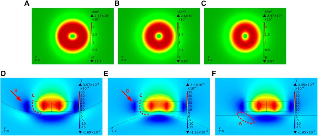
FIGURE 3. (A), (B), and (C) are the eddy current distributions on concave, plane, and convex surfaces. (D), (E), and (F) are the
The eddy current density on the isometric arcs, directly below the excitation coil, was extracted in different models, as shown in Figure 4A. The eddy current density curve of the concave model has a higher peak value and a wider distribution range than that of the plane model, while the curve of the convex model has a lower peak value and a narrower distribution range than the plane model.
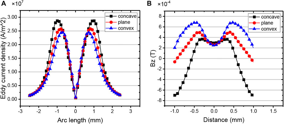
FIGURE 4. (A) Eddy current density distribution curve on the analysis path. (B)
3.3 Spatial magnetic field under different curved models
According to Section 3.2, the eddy current distribution changes when the curvature radius of the model changes, resulting in the changes of the secondary magnetic field
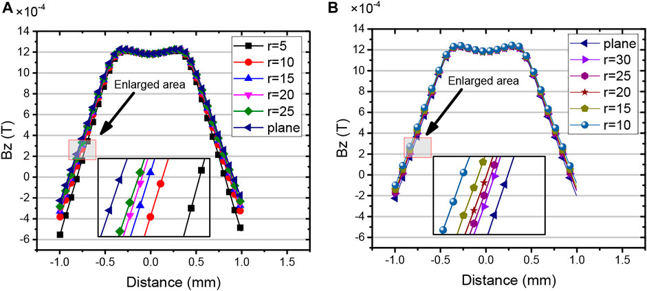
Furthermore,
3.4 Effect of the curvature radius on the eddy current distribution
In this section, the defect of 8 mm × 0.4 mm×0.5 mm is set. The length is along the circumferential direction, the width is along the axial direction, and the depth is vertical to the specimen surface. The excitation coil and the receiving coil are symmetrically distributed about the defect center line. Figures 5A,B show the local eddy current distribution of the concave model and the convex model with different radii, respectively.
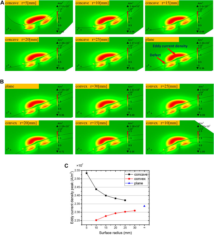
FIGURE 5. (A) and (B) are the eddy current distribution densities of concave and convex models. (C) Eddy current density peak curve with different surface radii.
The eddy current distribution is disturbed by defects in all the models, and the eddy current density differs significantly as the curvature radius of the model changes. It is worth noting that the change trend of the eddy current density is different between the concave models and the convex models. The peak value of the eddy current density in Figures 5A,B is further extracted and fitted to obtain the curves, as shown in Figure 5C. The eddy current density decreases gradually with the increase of the surface radius for the concave model, and the change trend is usually gentle. The peak value of the eddy current density increases with the increase of the surface curvature radius for the convex model, and the change trend is usually gentle.
Figure 6 shows the
3.5 Effect of the curvature radius on the eddy current testing signal
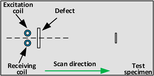
In this section, the parametric scanning function of COMSOL software is used to simulate the process of coils scanning through defects by changing the position of the coils relative to the defect. The coils are placed symmetrically about the defect, and the scanning direction is along the axial direction of the test piece, as shown in Figure 9. Then, the induced voltage change of the receiving coil on the scanning path is obtained. For concave models, the curvature radius is set from 5 mm to 25 mm in 5-mm steps, and the curvature radius is set from 10 mm to 30 mm in 5-mm steps for convex models. The detection signals of defects under models with different curvature radii are shown in Figure 7.

FIGURE 7. Induced voltage curve of the receiving coil. (A) Concave model; (B) convex model; (C) induced voltage amplitude.
It can be seen from Figures 7A,B that the induction voltage curve of the receiving coil presents “valley” features. Each curve reaches the valley at x = 0, indicating that the coils reach directly above the defect, while both ends of each curve tend to be smooth, indicating that there is no defect. We extract the amplitude of the induced voltage of each curve by making a difference between the voltage at x = 4 and x = 0. The relationship curve between the induced voltage amplitude and the radius of curvature is obtained by fitting, as shown in Figure 7C. It can be seen in Figure 7C that the induction voltage amplitude of the receiving coil increases gradually with the increase of the curvature radius under the concave model, while it decreases gradually with the increase of the curvature radius under the convex model.
4 Experiments
4.1 Experimental equipment
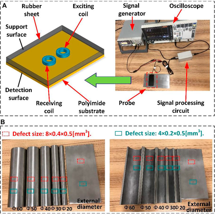
In this section, a series of experiments are designed to analyze the signal characteristics of different curved surfaces. Figure 8A shows the experimental devices used in this work, which is mainly composed of the signal generator, oscilloscope, probe, and signal processing circuit. The signal generator provides a sinusoidal voltage signal of 120 kHz, 3 V for the excitation coil. The coils are supported by a flexible polyimide substrate, which can adaptively fit the surface for specimens with different curvature radii. The rubber sheet covers the other side of the coils to support and protect it. The relevant parameters of the coil are shown in Table 2.
The inner surface and outer surface of the stainless steel tube with different curvature radii are used as concave and convex surfaces, respectively. The material of all specimens is 304 stainless steel, and the thickness is 5 mm. Two kinds of artificial defects are carved on the inner surface and the outer surface of the hollow stainless steel tube, respectively, and their dimensions are 8 mm × 0.4 mm×0.5 mm and 4 mm × 0.2 mm×0.5 mm, respectively. All defects lie along the circumference of the specimens. The dimensional parameters of the test piece and the real picture are shown in Table 3 and Figure 8B.
4.2 Effect of the curvature radius on the detection signal
All the defects on curved specimens with different curvature radii are tested to obtain the change trend of the ECT signal. The excitation coil and the receiving coil are placed symmetrically about the defect center line, as shown in Figure 9. The scanning direction is perpendicular to the defect direction. The testing results of two defects are shown in Figure 10.
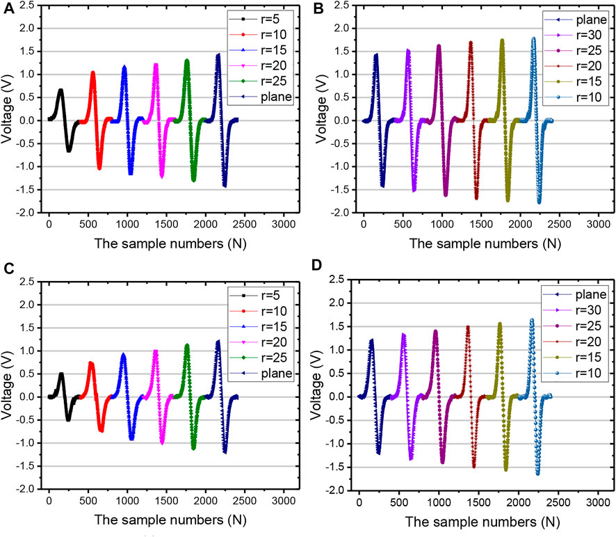
FIGURE 10. Detection signal of defect 1 (8 mm × 0.4 mm×0.5 mm). (A) Concave; (B) convex. Detection signal of defect 2 (4 mm × 0.2 mm×0.5 mm). (C) Concave; (D) convex.
As shown in Figure 10, compared with the signal on the plane specimen, concave surfaces weaken the signal, while convex surfaces enhance the signal. This phenomenon becomes significant as the curvature radius decreases. In Figure 10A, the signal amplitude of defect l increases with the increase of the curvature radius for the concave specimen. The minimum amplitude is 0.66 V, and the overall peak coverage range of the curve is between 0.66 V and 1.42 V in Figure 10A. However, it can be seen in Figure 10B that the amplitude of the detection signal decreases with the increase of the curvature radius for the convex specimen. The maximum amplitude is 1.78 V, and the overall peak coverage range of the curve is between 1.42 V and 1.78 V. In Figures 10C,D, the change trend of the detection signal of defect 2 is the same as that of defect 1 in both the concave condition and convex condition. Furthermore, the amplitude values of all the signals in Figure 10 are extracted and fitted to obtain a relationship curve between the signal amplitude and the curvature radius, as shown in Figure 11. It can be found that the slopes of two signal curves with different defect sizes are similar, which shows that the effect of specimen curvature radius on the defect detection signal is independent of the size of the defect itself. Then, relevant research is only conducted for defect 2.
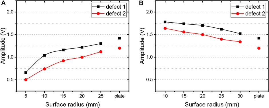
FIGURE 11. Amplitude curve of the detection signal. (A) Concave; (B) convex. Influence degree by curvature radius under different coil spacing.
According to Section 4.2, the change of curvature radius has a significant impact on the defect detection signal, whether in the concave surface or convex surface. In the actual design of the FECA probe, coil spacing is an important parameter. In this section, the distance between the coils is changed to explore the influence of the curvature radius of the specimen on the detection signal of the probe under different coil spacing. The coil spacing changes from 0.5 to 3 mm in 0.5-mm steps. The fitting curves of signal amplitude–coil spacing under different curvature radii are shown in Figures 12A,B. For different curvature radii, the signal amplitude–coil spacing curves show the same trend. The signal amplitude increases with the increase of coil spacing and reaches the maximum when coil spacing is 2.0 mm; then, it decreases for all the curvature radii in both the concave and convex surfaces.
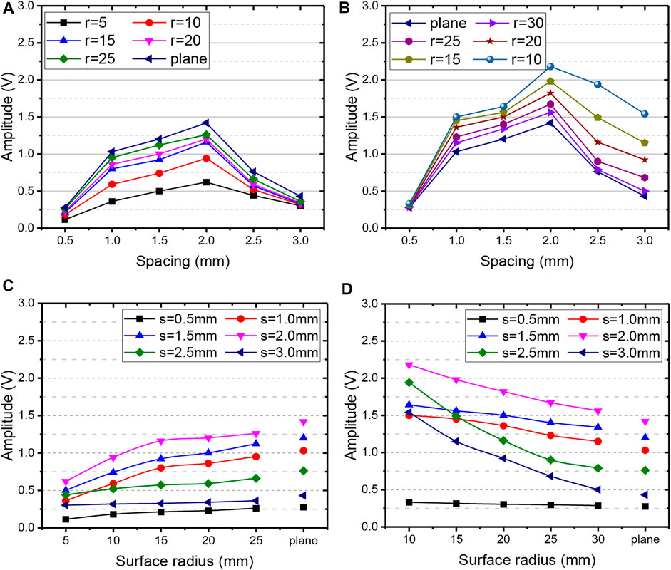
FIGURE 12. Fitting curve of signal amplitude–coil spacing under different curvature radii. (A) Concave; (B) convex. Signal amplitude–curvature radius fitting curve under different coil spacing. (C) Concave; (D) convex.
In actual detection, it is desirable to obtain a higher signal amplitude, but at the same time, it is desirable that the signal fluctuation caused by the change of the surface curvature radius of the specimen is smaller. The fitting curves of signal amplitudes at different curvature radii are shown in Figures 12C,D. All the curves show an upward trend as the curvature radius increases in the concave surface. However, the change trend is the opposite for the convex surface. In Figures 12C,D, the slope of the curves is significantly different under different coil spacing, indicating that probes with different spacing are affected by curvature radius of various degrees. Specifically, some coil spacing has larger signal fluctuation for the detection of complex curved surfaces, which may reduce the consistency of detection signals and the accuracy of defect evaluation.
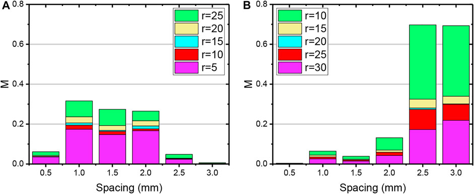
The fluctuation of the detection signals under different spacing in Figure 12 are further analyzed and shown in Figure 13. The fluctuation degree of the signal is defined as Eq. 4.1,
Here,
According to Eq. 4.1, the
5 Discussion and conclusion
In the FECA testing method, the defect on the surface of the specimen is detected by monitoring the change of the coil magnetic flux. The lift-off between the flat excitation coil and the curved surface becomes uneven, owing to the local curvature radius of the complex components, leading to the change in the eddy current distribution and the magnetic field sensed by the receiving coil. In addition, the relative position of the receiving coil will also change because of the curvature radius of the specimen, resulting in changes in the magnetic flux of the receiving coil. Based on a series of experiments and simulations, the results indicate that curvature radius has significant effects on the FECA probe, which is mainly reflected in these aspects:
(1) For the concave specimen, the lift-off at both sides of the coils is smaller, the eddy current is stronger, the magnetic field generated by the eddy current has a greater suppression effect to the spatial magnetic field, and the change of the spatial magnetic field picked up by the receiving coil is smaller. These conjectures are confirmed in the simulation. The results are opposite for convex specimens. This work reveals the impact mechanism of curvature radius on the defect detection signal.
(2) Compared with the signal on the plane specimen, concave surfaces weaken the signal, while convex surfaces enhance the signal. The amplitude of the experimental signal decreases with the decrease of the curvature radius for the concave surface, while it increases with the decrease of the curvature radius for the convex surface. The defect size and coil spacing do not change the law.
(3) The curved surface leads to weakened or enhanced ECT signals, which reduces the accuracy and consistency of inspection results for defect evaluation. The signal amplitude and fluctuation characteristic of different spacing probes are affected by the curvature radius. Certain coil spacing can guarantee larger detection signal amplitudes, but this does not mean that better signal consistency can be guaranteed in the case of changes in the curvature radius. It can provide guidance for the design of the FECA probe in practical application, according to the data results of amplitude and fluctuation characteristics under different spacing and different curvature radii.
Changing the coil spacing may avoid the effect of curvature radius on FECA signals so as to achieve a balance between signal consistency and signal amplitude. Clarifying the effects of curvature radius on the FECA sensor for the curved surface is of great significance for precision evaluation of cracks and related applications. Further studies on the influence elimination of curvature radius, such as signal compensation and parameter optimization, will be discussed in future study.
Data availability statement
The raw data supporting the conclusions of this article will be made available by the authors, without undue reservation.
Author contributions
ZD: writing—reviewing and editing, and funding acquisition. DL: data curation and validation. PQ: software. WS: methodology. TC: methodology. XS: resources. YK: conceptualization. All authors have read and agreed to the published version of the manuscript.
Funding
The authors acknowledge continuous supports by the National Natural Science Foundation of China (NSFC, Grant No. 52105550), the Natural Science Foundation of Hubei Province (Grant No. 2021CFB290), and the Knowledge Innovation Project of Wuhan (Grant No. 2022010801020266).
Conflict of interest
Authors Pan Qi and WS were employed by the company China Nuclear Power Operation Technology Co., Ltd.
The remaining authors declare that the research was conducted in the absence of any commercial or financial relationships that could be construed as a potential conflict of interest.
Publisher’s note
All claims expressed in this article are solely those of the authors and do not necessarily represent those of their affiliated organizations, or those of the publisher, the editors, and the reviewers. Any product that may be evaluated in this article, or claim that may be made by its manufacturer, is not guaranteed or endorsed by the publisher.
References
1. García-Martín J, Gómez-Gil J, Vázquez-Sánchez E. Non-destructive techniques based on eddy current testing. Sensors (2011) 11:2525–65. doi:10.3390/s110302525
2. Le Bihan Y, Pávó J, Marchand C. Characterization of small cracks in eddy current testing. Eur Phys J Appl Phys (2008) 43:231–7. doi:10.1051/epjap:2008112
3. Helifa B, Oulhadj A, Benbelghit A, Lefkaier IK, Boubenider F, Boutassouna D. Detection and measurement of surface cracks in ferromagnetic materials using eddy current testing. Ndt E Int (2006) 39:384–90. doi:10.1016/j.ndteint.2005.11.004
4. Song Z, Yamada T, Shitara H, Takemura Y. Detection of damage and crack in railhead by using eddy current testing. J Electromagn Anal Appl (2011) 03:546–50. doi:10.4236/jemaa.2011.312082
5. Rifai D, Abdalla AN, Khamsah N, Aizat M, Fadzli M. Subsurface defects evaluation using eddy current testing. Indian J Sci Technol (2016) 9:10–17485. doi:10.17485/ijst/2016/v9i9/88724
6. Naeimi M, Li Z, Qian Z, Zhou Y, Wu J, Petrov RH, et al. Reconstruction of the rolling contact fatigue cracks in rails using X-ray computed tomography. Ndt E Int (2017) 92:199–212. doi:10.1016/j.ndteint.2017.09.004
7. Clark R. Rail flaw detection: Overview and needs for future developments. NDT E Int (2004) 37:111–8. doi:10.1016/j.ndteint.2003.06.002
8. Grimberg R, Udpa L, Savin A, Steigmann R, Palihovici V, Udpa SS. 2D Eddy current sensor array. NDT E Int (2006) 39:264–71. doi:10.1016/j.ndteint.2005.08.004
9. Gilles-Pascaud C, Decitre J-M, Vacher F, Fermon C, Pannetier M, Cattiaux G. Eddy current flexible probes for complex geometries. AIP Conf Proc (2006) 820:399–406.
10. Bureau J-F, Ward RC, Jenstead W. Advances in eddy current array sensor technology. In: 17th World Conference on Nondestructive Testing; Shanghai, China (2008). p. p25–28.
11. Joubert P-Y, Vourc’h E, Thomas V. Experimental validation of an eddy current probe dedicated to the multi-frequency imaging of bore holes. Sensors Actuators A: Phys (2012) 185:132–8. doi:10.1016/j.sna.2012.07.009
12. Le M, Kim J, Kim J, Do HS, Lee J. Nondestructive testing of moisture separator reheater tubing system using Hall sensor array. Nondestructive Test Eval (2018) 33:35–44. doi:10.1080/10589759.2017.1331231
13. Lee J, Jun J, Kim J, Choi H, Le M. Bobbin-type solid-state hall sensor array with high spatial resolution for cracks inspection in small-bore piping systems. IEEE Trans Magn (2012) 48:3704–7. doi:10.1109/tmag.2012.2199472
14. Janosek M, Vyhnanek J, Ripka P. CW metal detector based on AMR sensor array. In: SENSORS, 2011 IEEE; 28-31 October 2011; Limerick, Ireland. IEEE (2011). p. 1515–7.
15. Allweins K, Von Kreutzbruck M, Gierelt G. Defect detection in aluminum laser welds using an anisotropic magnetoresistive sensor array. J Appl Phys (2005) 97:10Q102. doi:10.1063/1.1852391
16. D’Zurko D, Association NG, Development of an AMR eddy current-based crack detection sensor for live inspection of unpiggable transmission natural gas pipelines, (2019).
17. Ye C, Huang Y, Udpa L, Udpa SS. Novel rotating current probe with GMR array sensors for steam generate tube inspection. IEEE Sens J (2016) 16:4995–5002. doi:10.1109/jsen.2016.2556221
18. Postolache O, Ribeiro AL, Ramos HG. GMR array uniform eddy current probe for defect detection in conductive specimens. Measurement (2013) 46:4369–78. doi:10.1016/j.measurement.2013.06.050
19. Rifai D, Abdalla AN, Razali R, Ali K, Faraj MA. An eddy current testing platform system for pipe defect inspection based on an optimized eddy current technique probe design. Sensors (2017) 17:579. doi:10.3390/s17030579
20. Tao Y, Peng L, Li X, Ye C. Eddy current probe with integrated tunnel magnetoresistance array sensors for tube inspection. IEEE Trans Magn (2020) 56:1–8. doi:10.1109/tmag.2020.2981435
21. Zhang N, Ye C, Peng L, Tao Y. Eddy current probe with three-phase excitation and integrated array tunnel magnetoresistance sensors. IEEE Trans Ind Electron (2020) 68:5325–36. doi:10.1109/tie.2020.2989704
22. Peng L, Zhang N, Tao Y, Ye C. Fastener tilt assessment based on magnetic field image obtained with array tunnel magnetoresistance sensors. IEEE Trans Instrum Meas (2020) 70:1–9. doi:10.1109/tim.2020.3011782
23. Ye C, Wang Y, Tao Y. High-density large-scale TMR sensor array for magnetic field imaging. IEEE Trans Instrum Meas (2018) 68:2594–601. doi:10.1109/tim.2018.2866299
24. Karpenko O, Ye C, Udpa L. Dual frequency fusion for defect signal enhancement in EC-GMR inspecton of riveted multilayer structures. NDT E Int (2017) 92:97–103. doi:10.1016/j.ndteint.2017.07.015
25. Chen T, He Y, Du J. A high-sensitivity flexible eddy current array sensor for crack monitoring of welded structures under varying environment. Sensors (2018) 18:1780. doi:10.3390/s18061780
26. Zhang N, Ye C, Peng L, Tao Y. Novel array eddy current sensor with three-phase excitation. IEEE Sens J (2019) 19:7896–905. doi:10.1109/jsen.2019.2919661
27. Marchand B, Decitre J-M, Sergeeva-Chollet N, Skarlatos A. Development of flexible array eddy current probes for complex geometries and inspection of magnetic parts using magnetic sensors. AIP Conf Proc (2013) 1511:488–93. doi:10.1063/1.4789087
28. Fan X, Chen T, He Y, Du J. Influence of spatial winding distribution of flexible eddy current sensor on quantitative monitoring of subsurface cracks. Measurement (2021) 178:109382. doi:10.1016/j.measurement.2021.109382
29. Zhang H, Ma L, Xie F. A method of steel ball surface quality inspection based on flexible arrayed eddy current sensor. Measurement (2019) 144:192–202. doi:10.1016/j.measurement.2019.05.056
30. Sun Z, Cai D, Zou C, Zhang W, Chen Q. Design and optimization of a flexible arrayed eddy current sensor. Meas Sci Technol (2017) 28:045105. doi:10.1088/1361-6501/aa5b76
31. Sun Z, Cai D, Zou C, Zhang W, Chen Q. A flexible arrayed eddy current sensor for inspection of hollow axle inner surfaces. Sensors (2016) 16:952. doi:10.3390/s16070952
32. Li P, Cheng L, He Y, Jiao S, Du J, Ding H, et al. Sensitivity boost of rosette eddy current array sensor for quantitative monitoring crack. Sensors Actuators A: Phys (2016) 246:129–39. doi:10.1016/j.sna.2016.05.023
33. Sun H, Wang T, Liu Q, Qing X. A novel eddy current array sensing film for quantitatively monitoring hole-edge crack growth in bolted joints. Smart Mater Struct (2018) 28:015018. doi:10.1088/1361-665x/aae54e
34. Machado MA, Rosado L, Pedrosa N, Vostner A, Miranda RM, Piedade M, et al. Novel eddy current probes for pipes: Application in austenitic round-in-square profiles of ITER. NDT E Int (2017) 87:111–8. doi:10.1016/j.ndteint.2017.02.001
35. Xie S, Duan Z, Li J, Tong Z, Tian M, Chen Z. A novel magnetic force transmission eddy current array probe and its application for nondestructive testing of defects in pipeline structures. Sensors Actuators A: Phys (2020) 309:112030. doi:10.1016/j.sna.2020.112030
36. Zhao Y, Qi P, Xie Z, Bai P, Chen H-E, Xie S, et al. A new array eddy current testing probe for inspection of small-diameter tubes in Tokamak fusion devices. Fusion Eng Des (2020) 157:111627. doi:10.1016/j.fusengdes.2020.111627
37. Huang H, Sakurai N, Takagi T, Uchimoto T. Design of an eddy-current array probe for crack sizing in steam generator tubes. NDT E Int (2003) 36:515–22. doi:10.1016/s0963-8695(03)00050-1
38. Xin J, Lei N, Udpa L, Udpa SS. Nondestructive inspection using rotating magnetic field eddy-current probe. IEEE Trans Magn (2011) 47:1070–3. doi:10.1109/tmag.2011.2108996
39. Ye C, Xin J, Su Z, Udpa L, Udpa SS. Novel transceiver rotating field nondestructive inspection probe. IEEE Trans Magn (2015) 51:1–6. doi:10.1109/tmag.2015.2390144
40. Xie R, Chen D, Pan M, Tian W, Wu X, Zhou W, et al. Fatigue crack length sizing using a novel flexible eddy current sensor array. Sensors (2015) 15:32138–51. doi:10.3390/s151229911
41. Janovec M, Smetana M, Bugaj M. Eddy current array inspection of Zlin 142 fuselage riveted joints. Transportation Res Proced (2019) 40:279–86. doi:10.1016/j.trpro.2019.07.042
42. Zhang W, Wang C, Xie F, Zhang H. Defect imaging curved surface based on flexible eddy current array sensor. Measurement (2020) 151:107280. doi:10.1016/j.measurement.2019.107280
43. Endo H, Nishimizu A, Tooma M, Ouchi H, Yoshida I, Nonaka Y, et al. Signal evaluation system of flexible array ECT probes for inspecting complexly shaped surfaces. AIP Conf Proc (2011) 1335:597–603. doi:10.1063/1.3591905
44. Peng L, Ye C, Tao Y, Long C, Li M. Inspection of the undulation structure with an in-plane differential flexible array probe. In: 2021 IEEE 8th International Workshop on Metrology for AeroSpace (MetroAeroSpace); 23-25 June 2021; Naples, Italy. IEEE (2021). p. 547–51.
Keywords: curvature radius, flexible eddy current array, coil spacing, curved surface, metal components
Citation: Deng Z, Li D, Qi P, Shao W, Chen T, Song X and Kang Y (2022) Effects of curvature radius on flexible eddy current array sensors for the curved surface of metal components. Front. Phys. 10:988009. doi: 10.3389/fphy.2022.988009
Received: 06 July 2022; Accepted: 01 August 2022;
Published: 29 August 2022.
Edited by:
Maciej Roskosz, AGH University of Science and Technology, PolandReviewed by:
Jiuhao Ge, Nanjing University of Aeronautics and Astronautics, ChinaQing Zhang, Nanjing Tech University, China
Bo Hu, Nanchang Hangkong University, China
Copyright © 2022 Deng, Li, Qi, Shao, Chen, Song and Kang. This is an open-access article distributed under the terms of the Creative Commons Attribution License (CC BY). The use, distribution or reproduction in other forums is permitted, provided the original author(s) and the copyright owner(s) are credited and that the original publication in this journal is cited, in accordance with accepted academic practice. No use, distribution or reproduction is permitted which does not comply with these terms.
*Correspondence: Xiaochun Song, c29uZ3hjQG1haWwuaGJ1dC5lZHUuY24=
 Zhiyang Deng
 Danyu Li
 Pan Qi2