
95% of researchers rate our articles as excellent or good
Learn more about the work of our research integrity team to safeguard the quality of each article we publish.
Find out more
ORIGINAL RESEARCH article
Front. Phys. , 23 September 2022
Sec. Optics and Photonics
Volume 10 - 2022 | https://doi.org/10.3389/fphy.2022.987994
This article is part of the Research Topic Recent Progress in Ultrafast Laser Applications for Advanced Manufacturing View all 7 articles
 Duorui Gao1,2†
 Tianlun Li3†
 Zhuang Xie1,2Yuanchen He1Xiaotian Han1,2Shuaiwei Jia1,2Wei Wang1,2*Xiaoping Xie1,2*
Deep-space free-space optical (FSO) communication utilized the light wave as carriers for information transfer which has the major benefit of small size, lightweight, and low consumption compared with microwave communication loaded with the same data rate. The M-ary pulse-position modulation (M-PPM) format is a favorable choice for deep-space FSO communication by means of its high sensitivity. The preamplified thresholded M-PPM technique has been confirmed, and a corresponding demonstration has been accomplished with data rates of 1.25 Gbps and 2.00 Gbps separately. The receiving sensitivities (BER@1 × 10⁻³) of 1.25 Gbps and 2.00 Gbps 16-PPM have been detected as -57.51 dBm (11.04 photons/bit) and -55.03 dBm (12.25 photons/bit), respectively. Simultaneously, the high extinction ratio of M-PPM has been achieved, for example, the extinction ratio of 16-PPM has been detected as 39.51 and 38.27 dB for 1.25 Gbps and 2.00 Gbps, which are 17.60 and 17.44 dB higher than that of on–off keying (OOK) modulation, respectively. The results imply that our communication scheme possessed high sensitivity and eliminated the requirements of single-photon detectors (SPDs) and high-speed analog-to-digital converters (ADCs) which finds an alternative solution for deep-space FSO communication.
On-going advancements in science and technology ignite our passion for exploring the vast Universe. The utilization of natural resources is also gradually developing toward deep space; thus, the exploration of unknown deep space is of great significance [1,2,3,4]. Concurrently, the free-space optical (FSO) communication terminal can be considered an ideal payload for deep-space information transfer because of its inherent benefits of small size, light weight, and low power consumption [5, 6]. Therefore, FSO communication is capable of keeping up with the communication demands for booming deep-space activities.
Since the higher receiving sensitivity has been acquired for over-length deep-space transmission distance, the modulation formats serving for conventional near-Earth communication are less suitable, such as on–off keying (OOK), differential phase-shift keying (DPSK), binary phase-shift keying (BPSK), and quadrature phase-shift keying (QPSK) [7,8,9,10,11,12]. Hence, the M-ary pulse-position modulation (M-PPM) has been taken into consideration, which has long been recognized as a power-efficient format. M-PPM sacrificed the bandwidth for ensuring receiving sensitivity and approached the maximum data rate by using minimum optical power [13, 14]. Meanwhile, M-PPM has a great anti-interference ability during turbulent atmospheric transmission, which is fit for deep space–earth optical communication [15, 16]. In 2013, the 16-PPM and single-photon detector (SPD) array have been adopted in Lunar Laser Communication Demonstration (LLCD) by NASA for realizing 622 Mbps lunar–earth communication with 400,000 km distance [17, 18]. In 2022, NASA plans to launch an exploratory satellite Psyche loaded with 267 Mbps data rate utilizing PPM formats. It will run between Mars and Jupiter with 55 million km [19]. Meanwhile, NASA is going to launch a lunar-orbital satellite, which first carries the laser communication system (Optical to Orion, O2O) in 2023. The O2O will provide real-time 4 K video transmission owning ultra-high definition with a communication distance of 400,000 km and 80–250 Mpbs data-rate PPM downlink [20]. Additionally, ESA plans to send a weather satellite to Lagrangian point 5 (L5) equipped with a deep-space optical communication system (DOSC) to demonstrate the communication link with 150 million km in 2024. The downlink data rate is 10 Mbps with 16-PPM formats at 1,550 nm wavelength [21].
In this effort, the preamplified thresholded M-PPM optical communication system has been proposed and separately demonstrated with 1.25 Gbps and 2.00 Gbps, which eliminates the requirements for SPD as well as high-speed analog-to-digital converters (ADCs). An optically preamplified receiver can operate at very fast rates, achieve near theoretical performance, and is well suited to reliable operation in a space environment. Meanwhile, the high extinction ratio (ER) M-PPM modulation and the theory of preamplified thresholded receiving sensitivity have been introduced and analyzed. The corresponding 4-PPM, 8-PPM, and 16-PPM optical communication systems have been established, and relative parameters have been collected, including ER and eye diagrams, as well as bit-error-rate (BER). With a BER at 1 × 10⁻³, the receiving sensitivities of 1.25 Gbps and 2 Gbps 16-PPM signals are -57.51 dBm (11.04 photons/bit) and -55.03 dBm (12.25 photons/bit), respectively, which might perform well in deep-space FSO communication, such as lunar–Earth, Mars–Earth.
The M-PPM format achieves high receiver sensitivity utilizing the pulse relative position for information transfer [22]. In M-PPM, the k-bit data sequence has been divided into M-slot (M = 2k). Over a period of an M-slot symbol, a pulse represents 1 bit located at some time slot, and the other slots represent 0 bit. The k-bits data sequence has been expressed as K=(k1,k2,...,kn), and the position of the slot has been written as l. Therefore, the code mapping for M-PPM has been deduced as l = k1+2k2+......+2n−1kn
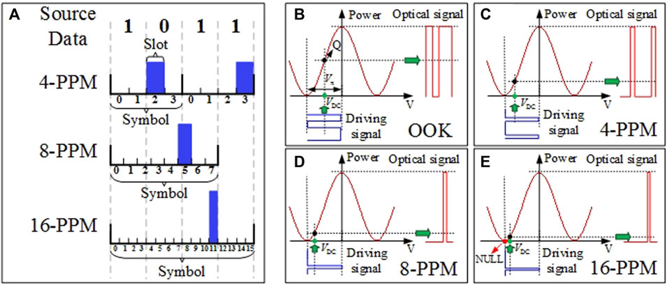
FIGURE 1. (A) Code mapping of the M-PPM (M = 4, 6, and 8) modulation format. (B–E) MZM transmission characteristics curves of OOK, 4-PPM, 8-PPM, and 16-PPM.
The PPM modulation format is a transmission mode with a high energy efficiency ratio. Compared with the OOK modulation, the optical signal-to-noise ratio (OSNR) of 4-PPM, 8-PPM, and 16-PPM has been multiplied 2, 4, and 8 times, respectively, with the same optical power. The peak optical power of PPM can be amplified to a fairly high level using an amplifier, which is more suitable for long-haul information transfer [24]. The Mach–Zehnder modulator-based (MZM-based) intensity modulation has been applied for the electro-optical modulation of the M-PPM signal. Since the MZM transmission characteristic is in accordance with the cosine curve, the optimum operation point of the modulator can be determined by controlling the direct current (DC) bias voltage (VDC). Meanwhile, the optimal ER has been approached by adjusting the signal-driving voltage as Vπ. As shown in Figures 1B–E, the optimal operation points VDC with high ER of OOK is the quadrature point (Q point, VDC = -Vπ/2), while that of M-PPM has not been located on the Q-point due to the uneven distribution of 0- and 1-bit electrical levels. For example, the optimal operation points of 4-PPM, 8-PPM, and 16-PPM are VDC = -3Vπ/4, VDC = -7Vπ/8, and VDC = -15Vπ/16 (close to NULL point), respectively.
The optical power of the pulsed signal amplified using the erbium-doped fiber amplifier (EDFA) at saturation power has been influenced by ER. The EDFA operated at the saturation status is an amplifier with limited average power, and its output peak power can be written as
where S represents the duty circle and Pavg is the average power. The correlation ER ≥ 15 dB-S has been satisfied for acquiring maximum amplified signal power. Thus, the demands ER4-PPM ≥ 21 dB, ER8-PPM ≥ 24 dB, and ER16-PPM ≥ 27 dB have been met for 4-PPM, 8-PPM, and 16-PPM, respectively, in order to exploit 99% power of EDFA for amplifying the pulse signal.
The optical preamplifier and electrical threshold decision have been combined for weak signal detection at the receiving terminal which eliminates the need for high-speed ADC. For instance, the time-slot rate of a 2-Gbps data stream coded by 16-PPM has reached 8 Gbps and requires ADC equipped with at least 16 GHz bandwidth, which introduces large power consumption, and simultaneously, it may be less suitable for applying in the space environment.
For an ideal noise-limited thresholded preamplified receiver, the M-PPM BER is approximately given by [25]
The keff is related to the bits-per-symbol given in Eqs 3–5 as follows:
where
where Navg represents the average photon number and
For small M and large received signal (Nc), keff would be next to k. The dependence of BER on photons/bit has been illustrated in Figure 2 for ideal optically preamplified M-PPM, OOK, and DPSK modulation formats. The BER performance has been improved with the increase in the order of M-PPM. Note that theoretical preamplified OOK and DPSK BER performances are similar to 2-PPM and 4-PPM modulation performances, respectively.
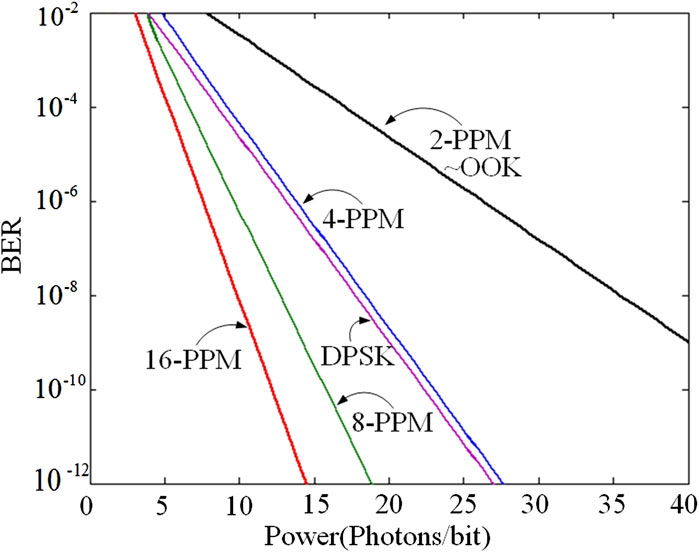
FIGURE 2. BER curves for optically preamplified M-PPM modulation, OOK modulation, and DPSK modulation.
The design of the preamplified thresholded M-PPM system has been illustrated in Figure 3, including the transmitter and receiver. Taking 16-PPM as a typical example, a distributed feedback (DFB) continuous laser with 10 kHz linewidth has been applied as the optical carrier for signal transmitting. The 1.25 Gbps or 2.00 Gbps baseband electrical signal (PRBS-7) has been PPM-coded as a 16-PPM signal with a slot-rate of 5.00 Gbps or 8.00 Gbps, respectively, and transferred into LiNbO3 MZM (iXblue, MXER-LN-20). The high ER PPM modulation has been approached viathe bias voltage VDC control of LiNbO3 MZM. Next, the modulated signal has been amplified by EDFA (KEOPSYS, CEFA-C-PB-HP) and coupled into an optical antenna for spatial emitting. Subsequently, the optical signal that underwent 1 m transmission has been captured using the receiving antenna and coupled into the following variable optical attenuator (VOA, Advanced Fiber Resources MVOA-1550). Then, a 50:50 coupler has been introduced to split the optical signal into two independent branches. One of the branches has been utilized as a power monitor, and the other branch of the optical signal has been amplified using a low-noise preamplifier and filtered by a 10-GHz optical filter for extracting the optical signal with low noise. The filtered optical signal has been transformed into the 16-PPM electrical signal using a high-speed photodetector (PD, Discovery, DSC-R402). Later, the electrical signal has been outputted as the differential signal after threshold decision shaping using the trans-impedance amplifier, RF filter, and high-speed comparator. One path of the differential signals has been imported into the 1:16 deserializer, and the other path goes through the phase-locked loop (PLL) to extract the stable synchronous clock signal as the reference clock signal for the 1:16 deserializer. For example, the serial slot-rate 5.00 Gbps or 8.00 Gbps 16-PPM signal has been divided into 16 paths of the parallel signal as 312.5 Mbps or 500 Mbps, respectively. Then, the 16 paths of the signal have been PPM-decoded and recovered as the baseband electrical signal via FPGA.
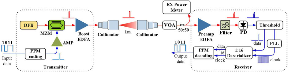
FIGURE 3. Schematic diagram of the preamplified thresholded M-PPM system. DFB: distributed feedback; MZM: Mach–Zehnder modulator; AMP: amplifier; EDFA: erbium-doped fiber amplifier; VOA: variable optical attenuator; PD: photodetector; PLL: phase-locked loop.
The spectra for modulated signals have been depicted in Figures 4A,B. Since the central wavelength is exactly 1,541.35 nm, various degrees of spectral broadening have been observed in modulated signals. For instance, the spectra of the 2.00 Gbps modulated signal broadening more than that of 1.25 Gbps, and both modulation sidebands are clear. Meanwhile, the duty cycle of the modulated signal has been decreased with the increase in the order of M-PPM; thus, the downtrend has been displayed for optical power. The eye diagrams of modulated signals are measured by a 23-GHz digital phosphor oscilloscope (Tektronix, DPO72304DX) (Figures 4C,D). All of the eye diagrams are clear and exhibit favorable great signal quality. The ERs of modulated 1.25 Gbps OOK, 4-PPM, 8-PPM, and 16-PPM have been measured as 21.91, 29.14, 37.67, and 39.51 dB, while those of 2.00 Gbps data are 20.83 dB m, 29.04, 36.20, and 38.27 dB, respectively. With the order of M-PPM increasing, the ER has been enhanced. The high ER of the modulated signal meets the requirement of the EDFA-saturated optical amplifier, which consumed 99% power for pulse signal amplification.
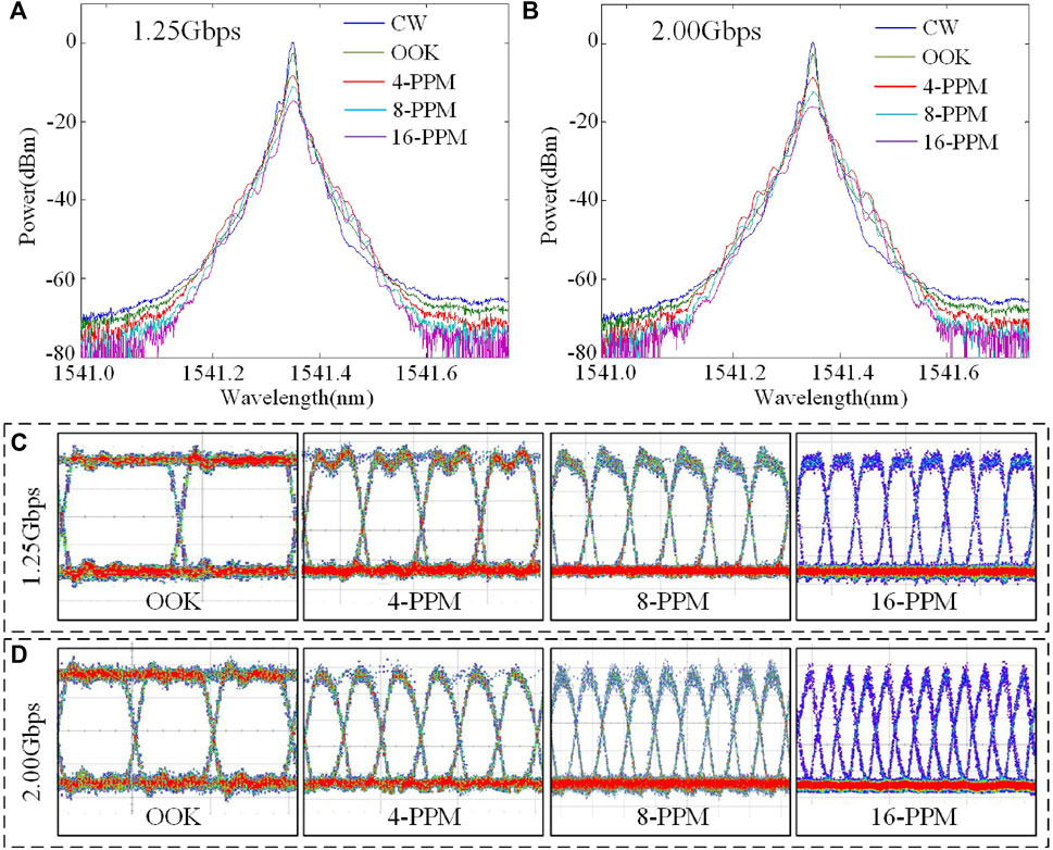
FIGURE 4. (A) Optical spectra of CW and 1.25 Gbps OOK, 4-PPM, 8-PPM, and 16-PPM signals; (B)Optical spectra of CW and 2.00 Gbps OOK, 4-PPM, 8-PPM, and 16-PPM signals; (C) eye diagrams of 1.25 Gbps modulated signals; and (D) eye diagrams of 2.00 Gbps modulated signals.
The receiving sensitivity plays a significant role in evaluating the performance of the receiver. The dependences of BER on optical power have been drawn in Figures 5A,B for 1.25 Gbps and 2.00 Gbps data rates with different formats. The receiving sensitivity has been improved with the increasing order of M-PPM modulation and conformed to the tendency of theoretical curves. The receiving eye diagrams with BER 1 × 10⁻⁹ have been depicted in Figures 5C,D, and the signal quality is worse than that of a transmitter (Figures 4C,D). The receiving sensitivities (BER@1 × 10⁻³) for OOK, 4-PPM, 8-PPM, and 16-PPM have been listed in Table 1. The receiving sensitivities for 1.25 Gbps and 2.00 Gbps 16-PPM are -57.51 dB m (11.04 photons/bit) and -55.03 dB m (12.25 photons/bit), respectively, which are separately 3.57 and 4.73 dB loss compared with the theoretical limit. The loss has been mainly induced by the 4.5 dB noise coefficient of the optical preamplifier, which is 1.5 dB higher than the theoretical value of 3 dB. Additionally, the 1.5 dB loss is aroused by the out-of-band noise of the optical filter; and the 0.5 dB loss is aroused from relative process circuits. Other reported PPM system results have been listed in Table 2 for the clear comparison with our present work. Our M-PPM communication system owns favorable receiving sensitivity and data rate which has potential for utilization in deep-space FSO applications.
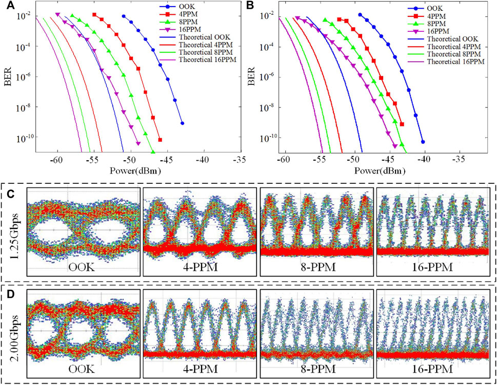
FIGURE 5. BER analysis of received optical power for (A) 1.25 Gbps and (B) 2.00 Gbps. (C) Eye diagrams of 1.25 Gbps and (D) 2 Gbps signals at the receiver terminal.
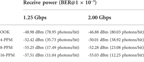
TABLE 1. Sensitivity results of the comparative experiment.
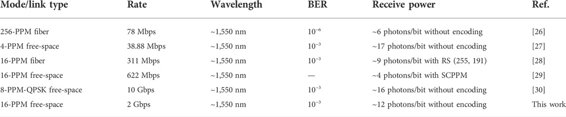
TABLE 2. Reported BER results for different PPM links.
A preamplified thresholded M-PPM technique has been proposed, and a corresponding system has been established. The high ER M-PPM modulation method and the theoretical receiving sensitivity have been analyzed. The modulated ERs of 1.25 Gbps and 2.00 Gbps 16-PPM have been measured as 39.51 and 38.27 dB, which are 17.60 and 17.44 dB higher than those of OOK modulation, respectively. The receiving sensitivities (BER@1 × 10⁻³) of 1.25 Gbps and 2.00 Gbps 16-PPM have been detected as -57.51 dBm (11.04 photons/bit) and -55.03 dBm (12.25 photons/bit), respectively. The preamplified PPM system has been confirmed with superior receiving sensitivity and eliminates the requirements for SPD and high-speed ADC. The performance evaluation of our PPM system demonstrates the high ER and favorable receiving sensitivity. The simple structure and optimal performance provide alternative solutions for deep-space FSO communication links including lunar–Earth, and Mars–Earth.
The original contributions presented in the study are included in the article/Supplementary Material; further inquiries can be directed to the corresponding authors.
DG, WW, and XX conceived the idea of the study; DG and TL wrote the manuscript; and all authors discussed the results and revised the manuscript.
This study was supported by the National Natural Science Foundation of China (61231012 and 91638101), National Key Research and Development Program of China (2018YFC0307904-02), and Fundamental Research Funds for the Central Universities (xzy022021039).
The authors declare that the research was conducted in the absence of any commercial or financial relationships that could be construed as a potential conflict of interest.
All claims expressed in this article are solely those of the authors and do not necessarily represent those of their affiliated organizations, or those of the publisher, the editors, and the reviewers. Any product that may be evaluated in this article, or claim that may be made by its manufacturer, is not guaranteed or endorsed by the publisher.
1. Xu G. Error performance of deep space optical communication with M-ary pulse position modulation over coronal turbulence channels. Opt Express (2019) 27:13344–13356. doi:10.1364/oe.27.013344
2. Wang Q, Cui L, Zhao H, Tan L, Ma J. Precision location approach in deep-space optical communications. Appl Opt (2021) 60:2854–2860. doi:10.1364/ao.419669
3. Deutsch LJ. Towards deep space optical communications. Nat Astron (2022) 4:907. doi:10.1038/s41550-020-1193-1
4. Gao D, Li T. Zoom optical system design for acousto-optic tunable filter camera assisted by programming multidimensional analysis. Appl Opt (2022) 61:5592–5598. doi:10.1364/ao.461525
5. Aveta F, Refai HH, LoPresti PG. Multiple access technique in a high-speed free-space optical communication link: Independent component analysis. Opt Eng (2019) 58:036111. doi:10.1117/1.oe.58.3.036111
6. Mai VV, Kim H. Beaconless pat and adaptive beam control using variable focus lens for free-space optical communication systems. APL Photon (2021) 6:020801. doi:10.1063/5.0039108
7. Gao D, Xie Z, Ma R, Wang W, Bai Z, Jia S, et al. Development current status and trend analysis of satellite laser communication[Invited]. Acta Photonica Sinica (2021) 50:0406001.
8. Su Y, Wang W, Hu X, Huang X, Wang Y, Si J, et al. 10 Gbps DPSK transmission over free-space link in the mid-infrared. Opt Express (2018) 26:34515–34528. doi:10.1364/oe.26.034515
9. Yu X, Zhang L, Zhang Y, Song Y, Tian M, Wang T, et al. 2.5 Gbps free-space optical transmission between two 5G airship floating base stations at a distance of 12 km. Opt Lett (2021) 46:2156–2159. doi:10.1364/ol.419690
10. Huang X, Xie X, Song J, Duan T, Hu H, Xu X, et al. Performance comparison of all-optical amplify-and-forward relaying FSO communication systems with OOK and DPSK modulations. IEEE Photon J (2018) 10:1–11. doi:10.1109/jphot.2018.2852301
11. Zhu Z, Janasik M, Fyffe A, Hay D, Zhou Y, Kantor B, et al. Compensation-free high-dimensional free-space optical communication using turbulence-resilient vector beams. Nat Commun (2021) 12:1666–8. doi:10.1038/s41467-021-21793-1
12. Billault V, Bourderionnet J, Mazellier JP, Leviandier L, Feneyrou P, Maho A, et al. Free space optical communication receiver based on a spatial demultiplexer and a photonic integrated coherent combining circuit. Opt Express (2021) 29:33134–33143. doi:10.1364/oe.433087
13. Xu G. BER and channel capacity of a deep space FSO communication system using L-PPM-MSK-SIM scheme during superior solar conjunction. Opt Express (2019) 27:24610–24623. doi:10.1364/oe.27.024610
14. Tzintzarov GN, Teng JW, Ildefonso A, Cressler JD. Analysis of the impact of radiation-induced optical transients on deep-space optical communications systems using PPM. In: Proceeding of the 2021 Optical Fiber Communications Conference and Exhibition (OFC); 06-10 June 2021; San Francisco, USA (2021). p. 1–3.
15. Ata Y, Baykal Y, Gökçe MC. M-ary pulse position modulation performance in non-Kolmogorov turbulent atmosphere. Appl Opt (2018) 57:7006–7011. doi:10.1364/ao.57.007006
16. Shin WH, Lee JW, Ha IH, Han SK. Data rate enhancement of free space optical communication using pulse positioned differential phase shift keying. Opt Express (2021) 29:26039–26047. doi:10.1364/oe.435060
17. Boroson DM, Robinson BS, Murphy DV, Burianek DA, Khatri F, Kovalik JM, Cornwell DM. Overview and results of the lunar laser communication demonstration. In: Free-space laser communication and atmospheric propagation XXVI. San Francisco, USA: SPIE (2014). p. 213–223.
18. Spellmeyer NW. Use of commercially available fiber optic components in emerging space laser communications applications: Optimizing performance, cost, and reliability. In: Proceeding of the 2021 Optical Fiber Communications Conference and Exhibition (OFC); 06-10 June 2021; San Francisco, USA (2021). p. 1–3.
19. Biswas A, Srinivasan M, Rogalin R, Piazzolla S, Liu J, Schratz B, et al. Status of NASA's deep space optical communication technology demonstration. In: Proceeding of the 2017 IEEE International Conference on Space Optical Systems and Applications (ICSOS) IEEE; 14-16 November 2017; Naha, Japan (2017). p. 23–27.
20. Robinson BS, Shih T, Khatri FI, Boroson DM, Burnside JW, Guldner O, et al. Laser communications for human space exploration in cislunar space: ILLUMA-T and O2O. Free-Space Laser Commun Atmos Propagation Front. Toxicol., SPIE (2018) 10524:231–235. doi:10.117/12.2291128
21. Sodnik Z, Heese C, Arapoglou PD, Schulz KJ, Zayer I, Daddato R. European deep-space optical communication program. Free-Space Laser Commun Atmos Propagation Front. Toxicol. SPIE (2018) 10524:214–222. doi:10.1117/12.2288943
22. Ata Y, Baykal Y, Gökçe MC. Performance of M-ary pulse position modulation for aeronautical uplink communications in an atmospheric turbulent medium. Appl Opt (2019) 58:7909–7914. doi:10.1364/ao.58.007909
23. Elsayed EE, Yousif BB. Performance enhancement of M-ary pulse-position modulation for a wavelength division multiplexing free-space optical systems impaired by interchannel crosstalk, pointing error, and ASE noise. Opt Commun (2020) 475:126219. doi:10.1016/j.optcom.2020.126219
24. Gökçe MC, Baykal Y, Ata Y. M-ary pulse position modulation performance in strong atmospheric turbulence. J Opt Soc Am A (2018) 35:2020–2025. doi:10.1364/josaa.35.002020
25. Caplan DO. Laser communication transmitter and receiver design. J Opt Fiber Commun (2007)4 109–246. doi:10.1007/s10297-006-0079-z
26. Caplan DO, Robinson BS, Murphy RJ, Stevens ML. Demonstration of 2.5-Gslot/s optically-preamplified M-PPM with 4 photons/bit receiver sensitivity. In: Proceeding of the Optical Fiber Communication Conference; 06-11 March 2005; Anaheim, CA, USA (2005). p. PDP32.
27. Stevens ML, Boroson DM. A simple delay-line 4-PPM demodulator with near-optimum performance. Opt Express (2012) 20:5270–5280. doi:10.1364/oe.20.005270
28. Spellmeyer NW, Bernstein SL, Boroson DM, Caplan DO, Fletcher AS, Hamilton SA, et al. Demonstration of multi-rate thresholded preamplified 16-ary pulse-position-modulation. In: Proceeding of the 2010 Conference on Optical Fiber Communication (OFC/NFOEC), collocated National Fiber Optic Engineers Conference; 21-25 March 2010; San Diego, CA, USA (2010). p. 1–3.
29. Grein ME, Kerman AJ, Dauler EA, Willis MM, Romkey B, Molnar RJ, et al. An optical receiver for the lunar laser communication demonstration based on photon-counting superconducting nanowires. Adv Photon Counting Tech IX, SPIE (2015) 9429:11–16. doi:10.1117/12.2179781
Keywords: space optical communication, deep-space communication, pulse-position modulation, preamplified thresholded receiving, high extinction ratio transmitting
Citation: Gao D, Li T, Xie Z, He Y, Han X, Jia S, Wang W and Xie X (2022) Performance evaluation of the high-speed deep-space optical communication system assisted by preamplified thresholded pulse-position modulation. Front. Phys. 10:987994. doi: 10.3389/fphy.2022.987994
Received: 06 July 2022; Accepted: 31 August 2022;
Published: 23 September 2022.
Edited by:
Qiyin Fang, McMaster University, CanadaReviewed by:
Sushank Chaudhary, Quanzhou Institute of Equipment manufacturing (CAS), ChinaCopyright © 2022 Gao, Li, Xie, He, Han, Jia, Wang and Xie. This is an open-access article distributed under the terms of the Creative Commons Attribution License (CC BY). The use, distribution or reproduction in other forums is permitted, provided the original author(s) and the copyright owner(s) are credited and that the original publication in this journal is cited, in accordance with accepted academic practice. No use, distribution or reproduction is permitted which does not comply with these terms.
*Correspondence: Wei Wang, d2FuZ3dlaTIwMTJAb3B0LmFjLmNu; Xiaoping Xie, eHhwQG9wdC5hYy5jbg==
†These authors have contributed equally to this work and share first authorship
Disclaimer: All claims expressed in this article are solely those of the authors and do not necessarily represent those of their affiliated organizations, or those of the publisher, the editors and the reviewers. Any product that may be evaluated in this article or claim that may be made by its manufacturer is not guaranteed or endorsed by the publisher.
Research integrity at Frontiers
Learn more about the work of our research integrity team to safeguard the quality of each article we publish.