- 1Faculty of Electronic Information and Electrical Engineering, Dalian University of Technology, Dalian, China
- 2National and Local Joint Engineering Research Center for Rail Transit Equipment, Dalian Jiaotong University, Dalian, China
- 3College of Electronics and Information Engineering, Shenzhen University, Shenzhen, China
A broadband multiple-input multiple-output (MIMO) antenna with high isolation operating in 3.14–5.42 GHz (2.28 GHz, 53.3%) is proposed for 5G smartphones. An offset T-shaped slot with dual functions is employed to improve the bandwidth of one antenna element and enhance the isolation. Then, the double L-shaped stubs are loaded to improve the impedance matching of the other antenna in the MIMO antenna. Finally, the 2 × 2 MIMO antenna is constructed by four T-shaped monopole antennas, two double L-shaped stubs, and two offset T-shaped slots. The proposed MIMO antenna is first simulated and then experimentally tested with a good agreement. High isolation of greater than 15 dB, high antenna efficiency of more than 54%, and low envelope correlation coefficient (ECC) of smaller than 0.08 are realized within 3.14–5.42 GHz. These good performances indicate that the proposed antenna can be applied for MIMO applications in smartphones.
Introduction
With the merits of enhancing the channel capacity and spectrum efficiency, the technology of multiple-input multiple-output (MIMO) can be a good candidate for realizing a high date rate of fifth-generation (5G) communication [1]. The 5G communication system is converged by multi-networks, which has a combination of global licensed 5G NR bands N77 (3.3–4.2 GHz), N78 (3.3–3.8 GHz), and N79 (4.4–5.0 GHz) [2]. Thus, it is urgent to realize wideband performances for 5G terminal antennas. So far, a large number of 5G MIMO antennas have been designed [3–9]. However, few works support the N77/N78/N79 and WLAN bands together. Due to the limited space of a terminal remaining for the antenna, it is difficult to establish a MIMO antenna with wide bandwidth and high isolation simultaneously. Increasing the bandwidth and enhancing the isolation of MIMO antennas have attracted much attention [10–16].
In order to improve the isolation, different techniques have been proposed. A simple design of a 5G MIMO antenna is arranging antenna elements in different parts of the smartphone, far enough to enhance the isolation [17]. However, this method will increase the size of the antenna with a profile of 13 mm, and put more pressure on the limited smartphone space. In [18], the center-placed T-shaped decoupling stub is introduced to improve the isolation, which is larger than 11.5 dB within 3.3–4.2 GHz. Recently, the two closely positioned or shared aperture antenna pair is proposed to construct the MIMO antenna without using any additional decoupling structure [19–21]. In [19], a differentially-fed dipole and a commonly-fed dipole antennas are combined back to back. High isolation of 24.2 dB is realized, but the bandwidth is only 3.35–3.63 GHz. The isolation of the antenna pair in [20] is increased to 24.1 dB within the corresponding working band, however, the bandwidth of this antenna is only 3.4–3.6 GHz. In [21], the bandwidth is expanded to 3.2–4.2 GHz, but the isolation is only better than 10.5 dB, and a clearance of 2 mm is required. Therefore, most works can only realize high isolation but narrow bandwidth [3–21], which is incompetent to cover the global 5G frequency bands of N77/N78/N79 (3.3–5.0 GHz).
Recently, several wideband MIMO antennas covering N77/N78/N79 bands are proposed [22–27]. By introducing the capacitor to the shared aperture antenna pair [22], a broad impedance bandwidth (IMBW) of 3.3–5.0 GHz is achieved, but the isolation between the internal elements of the antenna pair is just better than 10 dB. The antennas in [23–27] can also cover N77/N78/N79 and wireless local area network (WLAN) bands, but the isolations between different antenna elements are only greater than 10∼12 dB. It is known that slots can be utilized to decrease the mutual coupling of the MIMO antennas, but the slots reported in the literature are all located in the middle of the antenna pair, leading to narrow bandwidths [28–33], which are insufficient to satisfy the N77/N78/N79 bands.
In this paper, a 2 × 2 MIMO antenna operating in 3.14–5.42 GHz (2.28 GHz, 53.3%) is proposed for N77/N78/N79 (3.3–5.0 GHz) and WLAN (5.15–5.35 GHz) bands. Different from the conventional decoupling slot located in the center of two antennas [28–33], an offset T-shaped slot is inserted into the ground for achieving isolation of larger than 15 dB across 3.14–5.42 GHz. Meanwhile, the T-shaped slot helps to expand the IMBW. By adding double L-shaped stubs, a wide band is achieved for the antenna pair. From the measured results, the total efficiency is greater than 54%, and the envelope correlation coefficient (ECC) between any two antenna elements is smaller than 0.08.
Antenna design and analysis
Antenna configuration
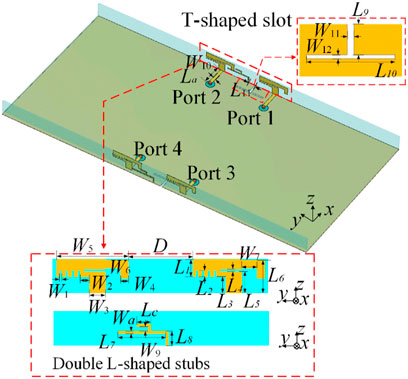
The detailed structure of the proposed MIMO antenna is presented in Figure 1. The antenna is designed using FR-4 substrates whose relative permittivity is 4.4 and loss tangent is 0.02. The proposed antenna is composed of four modified monopoles for a wide band. Offset T-shaped slots are used to enhance the isolation and bandwidth, and double L-shaped stubs are introduced to improve the impedance matching. The monopoles are printed on the inner surface of the FR-4 substrate, while the double L-shaped stubs are printed on the outer surface. The monopole antenna has a size of 14 mm3 × 0.8 mm3 × 6.7 mm3, and the distance between two antenna elements is 12.6 mm. The T-shaped slots are inserted on the ground plane at a distance of L11 from the center. The four antenna elements are fed by 50 Ω microstrip lines, which are positioned at the margin of the smartphone board having a dimension of 150 mm2 × 75 mm2. The antenna is designed and developed with electromagnetic simulation software CST. The optimized parameter dimensions of the proposed MIMO antenna are presented in Table 1 for fabrication.
Antenna analysis
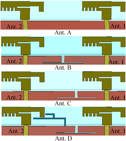
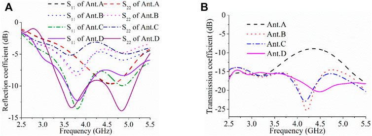
The design process of the MIMO antenna is demonstrated in Figure 2 step by step. Ant. A consists of two simple monopole antennas, showing a narrow IMBW of 3.8–5.2 GHz (1.4 GHz, 31.1%) for S11 lower than −6 dB and S21 more than -8 dB from Figure 3. To increase the isolation between the two antenna elements, a T-shaped slot in the middle is inserted on the ground plane, indicated as Ant. B, exhibiting isolation of higher than 14 dB from 3.3 to 5.5 GHz. However, the bandwidth at this time is very narrow, only covering 3.52–4.02 GHz (0.5 GHz, 13.5%) for antenna 1 and covering 3.48–4.06 GHz (0.58 GHz, 15.3%) for antenna 2. Then, the T-slot moves to the right side from the center, forming Ant. 3. It can be seen that the IMBW of Ant. 1 is expanded to 3.3–5.5 GHz (2.2 GHz, 50%), and isolation of more than 15 dB is obtained. However, the impedance matching of Ant. 2 is poor, as shown in Figure 3A. Finally, two double L-shaped stubs are introduced to improve the IMBW in Ant. D, with a reflection coefficient lower than -6 dB across 3.2–5.4 GHz (2.2 GHz, 51%) for Ant. 1 and 3.0–5.4 GHz (2.4 GHz, 57%) for Ant. 2. Moreover, the isolation is greater than 15 dB across 3.0–5.4 GHz.
Figure 4 shows the current distributions of Ant. A, B, C, and D at the center frequency of 4.2 GHz. With the introduction of the T-shaped slot, when port 1 is excited, the interference between Ant. 1 and Ant. 2 is greatly reduced [33], enhancing the isolation between port 1 and port 2 from 8 to 15 dB. Due to the high isolation, the Ant. 2 in Ants. B, C, and D exhibit little current when Ant. 1 is excited. However, the impedance matching effect of the antenna is very poor for Ant. 2. To broaden the bandwidth, double L-shaped stubs are employed, achieving a wide band of 3.0–5.4 GHz (2.4 GHz, 57%). The current distributions are depicted in Figure 4B when Ant. 2 is excited and Ant. 1 is matched by a 50 Ω load. It can be found that the currents on the double L-shaped stubs are strong, which can help improve the impedance matching of Ant. 2. At the same time, the currents on Ant. 1 are weak due to the T-shaped slot, thus, the isolation is still higher than 15 dB.
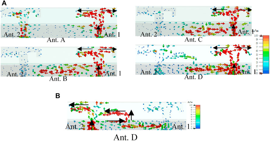
FIGURE 4. Current distributions at 4.2 GHz for (A) port 1 excited of Ants A-D, (B) port 2 excited of Ant D.
Parameter study
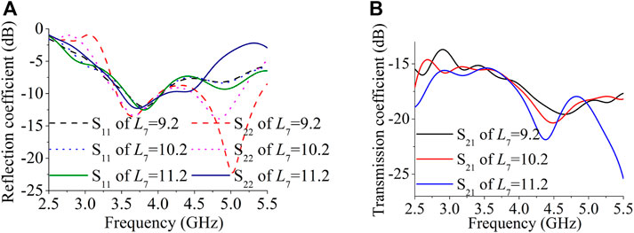
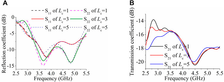
The effects of the length of the double L-shaped stubs on the antenna performance are investigated in Figures 5, 6. It can be found that the length L7 has little effect on S11 but a great effect on S22. With L7 increases from 9.2 to 10.2 and 11.2 mm, the bandwidth of S22 becomes narrower, from 3.32–5.5 GHz (2.18 GHz, 49.4%) to 3.2–5.38 GHz (2.18 GHz, 50.8%) and 3.18–4.8 GHz (1.62 GHz, 40.6%), while the isolation remains higher than 15 dB within 3.2–5.5 GHz. When Lc increases from 1 to 3 and 5 mm, S11 has insignificant variations, but the bandwidth of S22 varies from 3.30–5.41 GHz (2.11 GHz, 48.4%) to 3.2–5.38 GHz (2.18 GHz, 50.8%) and 3.26–5.28 GHz (2.02 GHz, 47.3%). The isolation below 3.5 GHz gets better when Lc increases. Therefore, to generate a wide IMBW and stable high isolation performance, the lengths of the double L-shaped stubs are optimized with L7 = 10.2 mm and Lc = 3 mm.
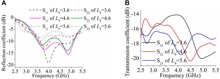
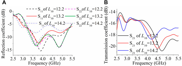
At the same time, the effects of the size of the T-shaped slot on the antenna performance are displayed in Figures 7, 8. It can be deduced the lengths L9 and L10 have a great effect on S11 and S21, but little effect on S22. With L9 increases from 3.6 to 4.6 and 5.6 mm, the worst isolation within the whole band gets better from 14 to 15.3 dB and 16.5 dB. When L10 increases, the isolation in the high-frequency band decreases. The offset distance of the T-shaped slot from the middle point is studied in Figure 9. It is observed that the offset distance has little effect on S11 but a great effect on S22. To achieve a wide band for both S11 and S21 with stable high isolation, the values of the T-shape slot are optimized with L9 = 4.6 mm, L10 = 13.2 mm, and L11 = 4.3 mm.
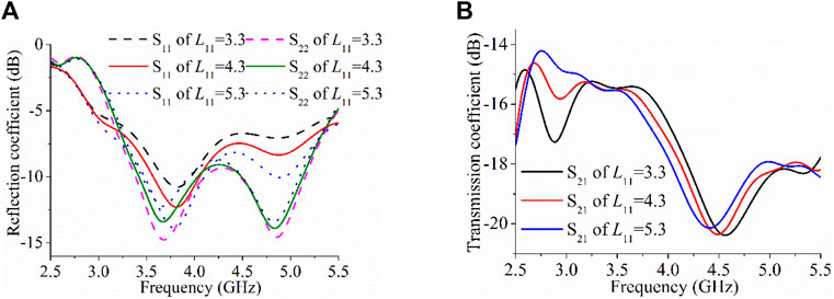
FIGURE 9. Simulated (A) reflection and (B) transmission coefficients for different offset distance L11.
Simulated and measured results
Performances of the proposed antenna
The simulated and measured reflection coefficients of Ant. 1 and Ant. 2 are shown in Figure 10A. In this figure, the simulated results exhibit a 6 dB IMBW of 3.2–5.4 GHz (2.2 GHz, 51%) for Ant. 1 and 3.0–5.4 GHz (2.4 GHz, 57%) for Ant. 2, while the corresponding measured IMBWs are 3.06–5.42 GHz (2.36 GHz, 55.7%) and 3.14–5.42 GHz (2.28 GHz, 53.2%). The overlaps between the S11 and S22 are 3.2–5.4 GHz (2.2 GHz, 51%) in simulation and 3.14–5.42 GHz (2.28 GHz, 53.2%) in measurement. The simulated and measured transmission coefficients (S12, S13, S14) between adjacent antenna elements of the four antennas are presented in Figure 10B. It can be observed that the isolation levels remain greater than 15 dB across the entire working band.
The radiation patterns of Ants. 1 and 2 in simulation and measurement at the center frequency of 4.2 GHz are depicted in Figure 11A good agreement between them is observed. The maximum gain directions of Ant. 1 and Ant. 2 are opposite to each other, thus resulting in a low ECC.
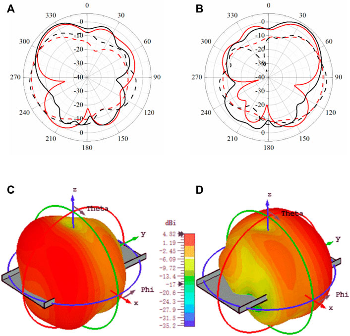
FIGURE 11. Radiation patterns at 4.2 GHz. (A) simulated and measured 2-D patterns in yoz plane of Ant. 1, (B) simulated and measured 2-D patterns in yoz plane of Ant. 2, (C) simulated 3-D patterns of Ant. 1, and (D) simulated 3-D patterns of Ant. 2. (—: Sim. Eθ, − −: Sim. Eϕ, —: Mea. Eθ, − −: Mea. Eϕ).
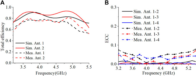
Due to the symmetrical structure, the efficiency of Ant. 1 and Ant. 2 are similar to that of Ant. 3 and Ant. 4. According to Figure 12, the simulated total efficiencies of Ant. 1 and Ant. 2 are higher than 72% across 3.2–5.4 GHz, and the measured efficiencies of the two antennas are higher than 54% across 3.14–5.42 GHz. The measured highest efficiency can reach 80%. To validate the MIMO potentials of the 2 × 2 MIMO antenna, its corresponding ECC is also studied based on the far-field. Figure 12B indicates that the simulated and measured ECCs across 3.2–5.4 GHz are lower than 0.08, which can satisfy the standards in smartphones [18].
User’s hand effect
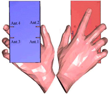
To investigate the hand effect on the performance of the proposed antenna, a model including the hand is simulated in Figure 13. The simulated results of reflection and transmission coefficients, and ECCs are depicted in Figure 14. Due to the hand effect, the bandwidths of Ants. 1-4 become 3.37–5.06 GHz, 2.65–5.16 GHz, 3.10–5.50 GHz, and 3.18–5.32 GHz. The isolation is higher than 19 dB between the adjacent antenna elements. As electromagnetic radiation can be absorbed by hand tissue, the efficiencies decrease but are higher than 26% for all the antennas. When the antenna is held by hand, the antenna element among Ants. 1-4 with higher efficiency can be selected to enhance the radiation. The simulated ECCs between adjacent antennas are lower than 0.05.
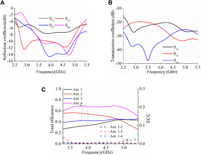
FIGURE 14. Simulated (A) reflection coefficient, (B) transmission coefficient, (C) total efficiency and ECC of the proposed antenna with a single-hand hold.
Comparison and discussion
The performance of the proposed antenna is compared with other works in Table 2. Among the MIMO antennas [3–27] for mobiles, only the antennas in [22–27] have sufficient bandwidths to cover N77/N78/N79 bands, but the isolations of these antennas are not enhanced. Compared with those antennas, the proposed antenna has greater isolation across 3.14–5.42 GHz, which can cover N77/N78/N79 and WLAN bands.
Conclusion
In this paper, offset T-shaped slots and double L-shaped stubs are introduced to realize a wideband MIMO antenna with high isolation. T-shaped slots not only help increase the isolation, but also help improve the IMBW of one antenna. In addition, double L-shaped stubs are used to improve the IMBW of the other antenna. Wideband, high isolation, and low ECC performances are obtained, indicating that the proposed MIMO antenna has the potential for future 5G smartphone applications.
Data availability statement
The original contributions presented in the study are included in the article/supplementary material, further inquiries can be directed to the corresponding authors.
Author contributions
CZ developed the concept and supervised the whole project. SC and JS carried out the simulations. NL and CL analyzed the simulation data. SC, JS, and CZ contributed to writing and finalizing the paper. All the authors contributed to paper revision and language editing.
Funding
This work was supported in part by the National Natural Science Foundation of China (Grant No. 62001080), Fundamental Research Funds for the Central Universities (Grant No. DUT22JC32), China Postdoctoral Science Foundation (Grant No. 2022M712439).
Conflict of interest
The authors declare that the research was conducted in the absence of any commercial or financial relationships that could be construed as a potential conflict of interest.
Publisher’s note
All claims expressed in this article are solely those of the authors and do not necessarily represent those of their affiliated organizations, or those of the publisher, the editors and the reviewers. Any product that may be evaluated in this article, or claim that may be made by its manufacturer, is not guaranteed or endorsed by the publisher.
References
1. Bogale TE, Le LB. Massive MIMO and mmwave for 5G wireless hetnet: Potential benefits and challenges. IEEE Veh Technol Mag (2016) 11:64–75. doi:10.1109/MVT.2015.2496240
2.Technical specification 38.101-1: NR; user equipment (UE) radio transmission and reception; Part 1: Range 1 standalone. (2019). available at:https://portal.3gpp.org/desktopmodules/Specifications/SpecificationDetails.aspx?specificationId=3283[Accessed Jun. 2019].
3. Jiang W, Liu B, Cui Y, Hu W. High-isolation eight-element MIMO array for 5G smartphone applications. IEEE Access (2019) 7:34104–12. doi:10.1109/ACCESS.2019.2904647
4. Ren A, Liu Y, Sim CYD. A compact building block with two shared-aperture antennas for eight-antenna MIMO array in metalrimmed smartphone. IEEE Trans Antennas Propag (2019) 67:6430–8. doi:10.1109/TAP.2019.2920306
5. Zhao A, Ren Z. Size reduction of self-isolated MIMO antenna system for 5G mobile phone applications. IEEE Antennas Wirel Propag Lett (2019) 18:152–6. doi:10.1109/LAWP.2018.2883428
6. Huang D, Du Z, Wang Y. Slot antenna array for fifth generation metal frame mobile phone applications. Int J RF Microw Comput Aided Eng (2019) 29:e21841–9. doi:10.1002/mmce.21841
7. Ban YL, Li C, Sim CYD, Wu G, Wong KL. 4G/5G multiple antennas for future multi-mode smartphone applications. IEEE Access (2016) 4:2981–8. doi:10.1109/ACCESS.2016.2582786
8. Zou H, Li Y, Sim CYD, Yang G. Design of 8 × 8 dual-band MIMO antenna array for 5G smartphone applications. Int J RF Microw Comput Aided Eng (2018) 28:e21420. doi:10.1002/mmce.21420
9. Hu W, Qian L, Gao S, Wen LH, Luo Q, Xu H, et al. Dual-band eight-element MIMO array using multi-slot decoupling technique for 5G terminals. IEEE Access (2019) 7:153910–20. doi:10.1109/ACCESS.2019.2948639
10. Wong KL, Lin BW, Lin SE. High-isolation conjoined loop multi-input multi-output antennas for the fifth-generation tablet device. Microw Opt Technol Lett (2019) 61:111–9. doi:10.1002/mop.31505
11. Serghiou D, Khalily M, Singh V, Araghi A, Tafazolli R. Sub-6 GHz dual-band 8 × 8 MIMO antenna for 5G smartphones. IEEE Antennas Wirel Propag Lett (2020) 19:1546–50. doi:10.1109/LAWP.2020.3008962
12. Li Y, Sim C, Luo Y, Yang G. Multiband 10-antenna array for sub-6 GHz MIMO applications in 5-G smartphones. IEEE Access (2018) 6:28041–53. doi:10.1109/ACCESS.2018.2838337
13. Sun L, Li Y, Zhang Z, Feng Z. Wideband 5G MIMO antenna with integrated orthogonal-mode dual-antenna pairs for metal-rimmed smartphones. IEEE Trans Antennas Propag (2019) 68:2494–503. doi:10.1109/TAP.2019.2948707
14. Xu KD, Zhu J, Liao S, Xue Q. Wideband patch antenna using multiple parasitic patches and its array application with mutual coupling reduction. IEEE Access (2018) 6:42497–506. doi:10.1109/access.2018.2860594
15. RenZhao ZA, Wu S. MIMO antenna with compact decoupled antenna pairs for 5G mobile terminals. IEEE Antennas Wirel Propag Lett (2019) 18:1367–71. doi:10.1109/LAWP.2019.2916738
16. Xu KD, Luyen H, Behdad N. A decoupling and matching network design for single- and dual-band two-element antenna arrays. IEEE Trans Microw Theor Tech (2020) 68:3986–99. doi:10.1109/tmtt.2020.2989120
17. Zhou Z, Liu S, Li W, An T, Hu Z. A wideband MIMO antenna with high isolation for 5G application. Int J RF Mic Comp-aid Eng (2021) 32:e23004. doi:10.1002/mmce.23004
18. Cui L, Guo J, Liu Y, Sim C. An 8-element dual-band MIMO antenna with decoupling stub for 5G smartphone applications. IEEE Antennas Wirel Propag Lett (2019) 67:2095–9. doi:10.1109/LAWP.2019.2937851
19. Xu H, Gao SS, Zhou H, Wang H, Cheng Y. A highly integrated MIMO antenna unit: Differential/common mode design. IEEE Trans Antennas Propag (2021) 69:6724–34. doi:10.1109/TAP.2019.2922763
20. Chang L, Yu Y, Wei K, Wang H. Polarization-orthogonal Co-frequency dual antenna pair suitable for 5G MIMO smartphone with metallic bezels. IEEE Trans Antennas Propag (2019) 67:5212–20. doi:10.1109/TAP.2019.2913738
21. Sun L, Li Y, Zhang Z, Wang H. Self-decoupled MIMO antenna pair with shared radiator for 5G smartphones. IEEE Trans Antennas Propag (2020) 68:3423–32. doi:10.1109/TAP.2019.2963664
22. Sun L, Li Y, Zhang Z. Wideband integrated quad-element MIMO antennas based on complementary antenna pairs for 5G smartphones. IEEE Trans Antennas Propag (2021) 69:4466–74. doi:10.1109/TAP.2021.3060020
23. Chen HD, Tsai YC, Sim C, Kuo C. Broadband eight-antenna array design for sub-6 GHz 5G NR bands metal-frame smartphone applications. IEEE Antennas Wirel Propag Lett (2020) 19:1078–82. doi:10.1109/LAWP.2020.2988898
24. Wong KL, Chen YH, Li WY. Decoupled compact ultrawideband MIMO antennas covering 3300∼6000 MHz for the fifthgeneration mobile and 5GHz-WLAN operations in the future smartphone. Microw Opt Technol Lett (2018) 60:2345–51. doi:10.1002/mop.31400
25. Zhang X, Li Y, Wang W, Shen W. Ultra-wideband 8-port MIMO antenna array for 5G metal-frame smartphones. IEEE Access (2019) 7:72273–82. doi:10.1109/ACCESS.2019.2919622
26. Cai Q, Li Y, Zhang X, Shen W. Wideband MIMO antenna array covering 3.3–7.1 GHz for 5G metal-rimmed smartphone applications. IEEE Access (2019) 7:142070–84. doi:10.1109/ACCESS.2019.2944681
27. Sim C, Liu HY, Huang CJ. Wideband MIMO antenna array design for future mobile devices operating in the 5G NR frequency bands n77/n78/n79 and LTE band 46. IEEE Antennas Wirel Propag Lett (2020) 19:74–8. doi:10.1109/LAWP.2019.2953334
28. Shuai Z, Lau BK, Tan Y, Ying Z, He S. Mutual coupling reduction of two PIFAs with a T-shape slot impedance transformer for MIMO mobile terminals. IEEE Trans Antennas Propag (2012) 60:1521–31. doi:10.1109/TAP.2011.2180329
29. Deng J, Li J, Zhao L, Guo L. A dual-band inverted-F MIMO antenna with enhanced isolation for WLAN applications. IEEE Antennas Wirel Propag Lett (2017) 16:2270–3. doi:10.1109/LAWP.2017.2713986
30. Park J, Choi J, Park J, Kim Y. Study of a T-shaped slot with a capacitor for high isolation between MIMO antennas. IEEE Antennas Wirel Propag Lett (2012) 11:1541–4. doi:10.1109/LAWP.2012.2226695
31. Karaboikis M, Soras C, Tsachtsiris G, Makios V. Compact dual-printed inverted-F antenna diversity systems for portable wireless devices. IEEE Antennas Wirel Propag Lett (2004) 3:9–14. doi:10.1109/LAWP.2004.825106
32. Ikram M, Nguyen-Trong N, Abbosh AM. Realization of a tapered slot array as both decoupling and radiating structure for 4G/5G wireless devices. IEEE Access (2019) 7:159112–8. doi:10.1109/ACCESS.2019.2950660
Keywords: wideband, MIMO, offset T-shaped slot, decouple, high isolation
Citation: Chen S, Lu N, Sun J, Zhou C, Li C and Wu D (2022) High-Isolation wideband MIMO antenna with offset T-Shaped slots for 5G/WLAN applications. Front. Phys. 10:986558. doi: 10.3389/fphy.2022.986558
Received: 05 July 2022; Accepted: 27 July 2022;
Published: 19 August 2022.
Edited by:
Kai-Da Xu, Xi’an Jiaotong University, ChinaCopyright © 2022 Chen, Lu, Sun, Zhou, Li and Wu. This is an open-access article distributed under the terms of the Creative Commons Attribution License (CC BY). The use, distribution or reproduction in other forums is permitted, provided the original author(s) and the copyright owner(s) are credited and that the original publication in this journal is cited, in accordance with accepted academic practice. No use, distribution or reproduction is permitted which does not comply with these terms.
*Correspondence: Changfei Zhou, Y2Z6aG91QGRsdXQuZWR1LmNu; Changxian Li, bGljaGFuZ3hpYW56anVAMTYzLmNvbQ==
 Shuyi Chen1
 Changfei Zhou
 Di Wu
Di Wu