- Guangdong Provincial Key Laboratory of Optical Information Materials and Technology, Institute of Electronic Paper Displays, South China Academy of Advanced Optoelectronics, South China Normal University, Guangzhou, China
Electrowetting display (EWD) is a new generation of reflective display technology with low power consumption and high contrast. To improve the response speed of pixels, an arc multi-electrode pixel was proposed, and its performance was verified by using the established three-dimensional model in this paper. According to the model, the influence of the arc multi-electrode pixel structure on response speed was simulated, and the influence of a driving sequence on oil movement inside pixels were analyzed. In addition, comparative experiments of oil movement inside pixels with single-electrode and arc multi-electrode were conducted. Experimental results showed that the response time of the arc multi-electrode structure was 0.9 ms faster than the single-electrode structure in a pixel opening stage. In the pixel closing stage, the oil recovery time can be accelerated by applying a boosting voltage to the electrode corresponding to the oil accumulation area, which was 2.3 ms faster than that of the single-electrode structure.
Introduction
Electrowetting is a phenomenon which uses an electric field to change the wettability of solid-liquid surface [1]. In recent years, electrowetting technology has been widely used in chemical industry, bioengineering, display, and other fields [2–4]. Among them, electrowetting displays (EWDs) are a new generation of reflective display technology [5, 6]. Compared with traditional reflective displays, EWDs have the advantages of low power consumption, high contrast, fast response, and full color [7, 8], which is one of the most attractive emerging display technologies [9].
A schematic diagram of EWDs structure is shown in Figure 1. The working principle of EWDs can be described as following two stages: At the first stage (named pixel opening stage), when a large enough voltage is applied, the surface tension between water and oil can be changed, the oil can therefore be squeezed by water, showing the color of the bottom substrate. During the second stage (named pixel closing stage), the voltage is turned off, charges accumulated at the polar liquid interface are completely released, resulting in the restore of the original equilibrium between the water and the insulation layer, showing the color of the oil. So, the effect of dynamic display for EWDs can be achieved. To quantify the response performance, the response time correlative to the on and off stages of pixels are defined as, 1) on-time refers to the time from applying the driving waveform to reaching the target aperture ratio of pixels. 2) off-time refers to the time from the target aperture ratio to 0.

FIGURE 1. Pixel structure of a EWD panel. The structure includes a top plate, ITO, fluid (colored oil and polar liquid), pixel wall, hydrophobic insulating layer, and substrate. Two representative stages show (A) the colored oil spreads on hydrophobic layer as the voltage off, and (B) the colored oil is pushed to a pixel corner when applied a voltage.
At present, the response speed of pixels still needs to be improved [10]. In terms of improving the response speed of pixels, an asymmetric driving scheme with alternating positive and negative voltage was proposed. This method could reduce the response time of pixels in the closing stage by suppressing the dielectric charge trapping, thus the fast response of EWDs could be achieved [11]. Similarly, a driving waveform contained an overload phase and a driving phase was proposed. This driving scheme reduced the time required for oil rupture by applying a short overload voltage, thus the purpose of improving pixels response speed could be achieved [12]. From the perspective of fluid characteristics inside pixels, surface tension at the interface of oil/water was considered to be an important factor affecting oil movement. A weak surface tension could increase the aperture ratio of pixels and reduce its response time [13]. In addition, the pixel response speed was also affected by the dynamic viscosity of oil and water. It has been shown that the lower the dynamic viscosity of two immiscible oil/water, the faster the response of pixels [14]. Moreover, the researchers proposed a pixel structure which added spacer arrays to adjacent pixel wall. This structure changed the oil/water interface balance by adding spacers to the pixel wall, it could achieve a consistent oil movement direction and reduce the oil rupture time. Therefore, the response speed of pixels could also be improved [15].
In this work, an arc multi-electrode pixel structure for improving the response speed of EWDs was proposed, and a three-dimensional EWD pixel simulation model was conducted by using COMSOL Multiphysics software. The influence of the arc multi-electrode and single-electrode on pixel response speed in this model was studied. Furthermore, a scheme for applying recovery waveform on sub-electrodes of arc multi-electrode was proposed to improve the oil recovery speed in the pixel closing stage.
Numerical methodology
The three-dimensional EWD simulation was achieved using the COMSOL Multiphysics software. A laminar flow two-phase flow framework was used in the model. The laminar flow field was coupled with a phase field and an electrostatic field. The problem of fluid flow in the laminar flow field was solved by Navier-Stokes equation. Electrical parameters in the electrostatic field were solved by Maxwell’s stress tensor equation. The voltage and electrostatic field force output in the electrostatic field was eventually coupled to the laminar flow field.
Governing equations
A phase-field method is used to build the model and investigate the dynamic process of a two-phase flow interface. A large number of data has been proved that the phase-field method could effectively predict droplet movement on the solid surface [16, 17]. The movement of interface is tracked indirectly by solving two equations. One of them is used to solve phase-field variable
Where
The laminar flow field can be solved by Navier-Stokes equation and continuity equation [22]. Navier-Stokes equation is described as Eq. 4. To depict the movement of two immiscible liquids, a transport of mass and a momentum are governed by incompressible Navier-Stokes equations.
Where
As described in Eqs. 4, 5, the coupling between the laminar flow field and the electrostatic field is achieved by applying an electrostatic volume force to Navier-Stokes equation. The electrostatic field force is a main factor that can cause fluid-flowing [18]. In addition, the electrostatic field force can be obtained by calculating the divergence based on Maxwell Stress Tensor (MST) [18], and the calculation is expressed by Eq. 6.
In a three-dimensional model simulation, MST is expressed as Eq. 7.
The variation of volume force caused by the electrostatic field acts on the interface between oil and water, and the calculation can be expressed by Eq. 8.
For the calculation of contact angle, it was shown in Eq. 9 [7].
Where
Boundary conditions
In the simulation model, the zero-charge boundary condition should be set on all sides of the model. For electrostatic field boundary conditions, the voltage and the ground needed to be specified. The wetted wall, the initial interface, and the outlet needed to be specified in phase-field boundary conditions. In addition, the contact angle was defined as the inverse operation of Lippmann-Young equation.
The interface of the two-phase flow was selected as an initial boundary condition. Both sides of the model (except the pixel walls) were selected as inlet and outlet boundary conditions. In addition, initial values of pressure and velocity in the laminar flow field were set to 0. The wall condition was set to Navier-Slip.
Process and discussion
Setting of model parameters
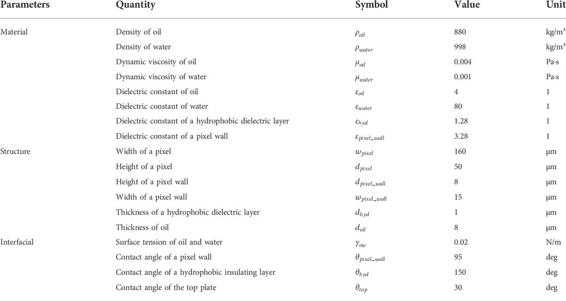
Parameters used in the simulation were shown in Table 1. The fluid (oil and water) in the model was set to incompressible flow. It was assumed that the temperature (25°C) was kept constant during fluid movement, the thermal expansion of fluid could be ignored. The influence of pressure on dynamic viscosity was ignored. In addition, the bond number described the relationship between gravity and surface tension, and it was far less than 1, thus the gravity could be neglected [18]. Moreover, the polar liquids were replaced by water [23, 24]. To compare the response speed of a single-electrode with that of an arc multi-electrode, the aperture ratio was required to characterize it. The ratio of white area to the pixel area was called aperture ratio, and it could be calculated by Eq. 10.
Where
Design of arc multi-electrode pixel structure
The arc multi-electrode pixel structure proposed in this paper had a faster response speed than single electrode, which could be elaborated from the following points. In electrowetting, when a droplet was subjected to an asymmetrical electric field force, it would be deformed on the side of the electric field force, which in turn caused the droplet to move [25, 26]. Similarly, in sessile EWDs, when a droplet was stationary, it was a semicircular shape, as shown in Figure 2A. When the droplet was subjected to a non-contact force on left, as shown in Figure 2B, the left droplet was deformed, and its inside would generate a velocity which was directed to the right. When the droplet was subjected to non-contact force on both sides at the same time, the two sides of the droplet were deformed and were contracted to the middle of the droplet, as shown in Figure 2C. In this case, it is not conducive to the droplet movement. Therefore, an asymmetric progressive stress was necessary to improve oil movement inside pixels in EWDs.

FIGURE 2. Deformation of a sessile droplet exerted by non-contact forces. Vertical arrows indicated the direction of non-contact force, and horizontal arrows indicated the direction of internal droplet velocity. (A) When the sessile droplet was stationary, it was a semicircular shape. (B) When the sessile droplet was subjected to a non-contact force on left, it was deformed on the left, and it had a tendency to move to right. (C) When the sessile droplet was subjected to non-contact force on both sides at the same time, it was deformed on both sides and was contracted to the middle of itself.
The proposed arc multi-electrode pixel structure was shown in Figure 3A, and the structure of source electrode was divided into four sub-electrode with arc shape, as shown in Figure 3B. Considering the difference of oil movement in a pixel structure (the oil near the pixel wall moved slowly due to a stronger capillary force, and the oil near the middle of pixel moved fast), spacers at sub-electrodes 1, 2, and 3 were set as an elliptical arc. The width of all spacers was 6 μm. When the spacer was set too large in experiment, it would cause the oil to rupture. If the spacer was set too small, it was meaningless. Other structures in the arc multi-electrode pixel remained the same as a traditional single-electrode pixel structure, as shown in Figure 3C. Figure 3D described a traditional single-electrode structure in EWDs.
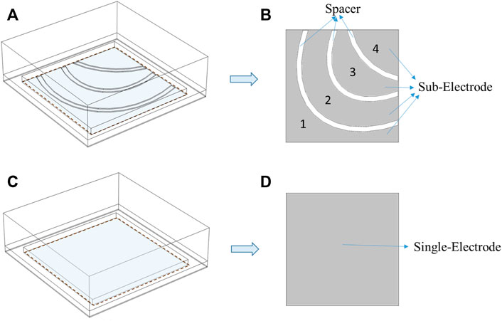
FIGURE 3. Arc multi-electrode and single-electrode pixel structure. (A) An arc multi-electrode pixel structure. (B) The arc multi-electrode contains 4 sub-electrodes and 3 spacers. The width of all spacers was 6 μm. (C) A single-electrode pixel structure. (D) A single-electrode.
Relationship between driving sequence and oil movement
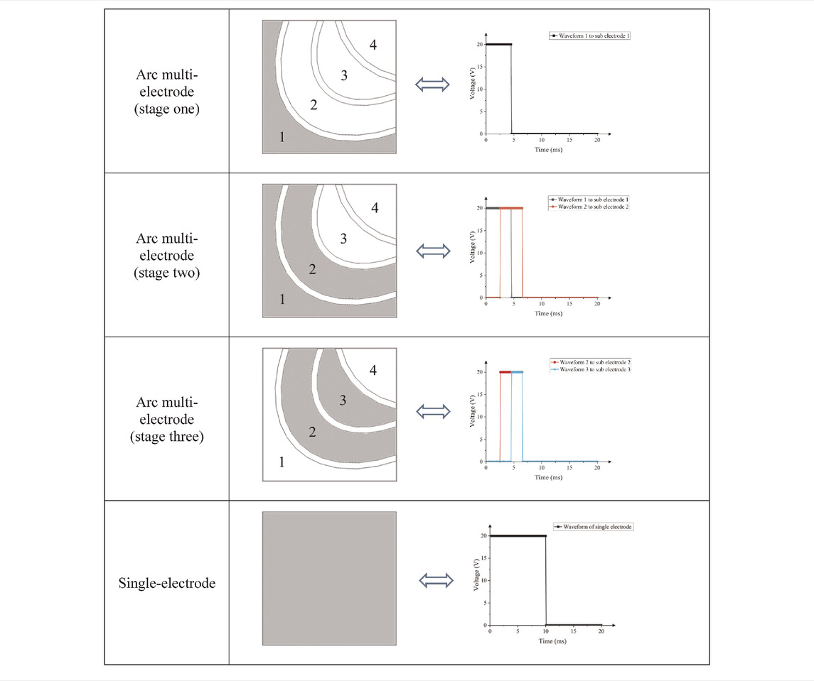
In the arc multi-electrode structure, corresponding driving waveforms were applied to different sub-electrodes at different times, as shown in Table 2, and all effective voltages were set 20 V. The gray area represented a selected sub-electrode, and waveforms in the table represented driving waveforms applied to the corresponding sub-electrode. In order to push oil to a pixel corner quickly, the driving was implemented in three stages. In stage one, the driving waveform 1 was applied to sub-electrode 1, oil was ruptured in area of electrode 1. In the second stage, the driving waveform 1 was continued to be applied to the sub-electrode 1, it allowed residual oil in the spacer between electrodes 1 and 2 to contract. At the same time, the driving waveform 2 was applied to sub-electrode 2. This driving mode could reduce oil dispersion and push oil to move in a fixed direction. In the third stage, the driving waveform at sub-electrode 1 was released, and the corresponding driving waveform was applied to the second and third sub-electrodes, so that oil was pushed to a pixel corner quickly. In the single-electrode comparison experiment, the same voltage was applied and the effective time was maintained for 10 ms, so oil could be completely opened until it remained unchanged. The mode of driving waveform applied to a single-electrode was shown in Table 2.
After applying driving waveforms mentioned in Table 2, the aperture ratio variation curves of single and arc multi-electrode pixels were shown in Figure 4. In the single-electrode, oil was ruptured at 0.9 ms. It took 4.1 ms for the pixel to reach 50% aperture ratio, and subsequently achieved the maximum aperture ratio of 55.9%. Whereas, in the arc multi-electrode, oil ruptured at 0.7 ms, the response time for pixels to reach 50% aperture ratio was 3.2 ms, and the maximum aperture ratio was 67%. Compared with single-electrode, the arc multi-electrode had obvious advantages in response speed and aperture ratio. The response time was 0.9 ms faster than the single-electrode, and the maximum aperture ratio was 11.1% larger than the single-electrode. Table 3 shows the shrinkage process of oil in a pixel.
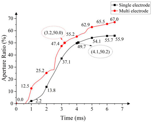
FIGURE 4. Evolution of the aperture ratio of arc multi-electrode and single-electrode in the pixel opening stage. The aperture ratio curves were obtained at a voltage of 20 V. Each curve consisted of 65 data points with an interval of 0.1 ms.
Boosting voltage and oil recovery
When driving waveforms were removed, oil naturally spread under the action of its own cohesive energy. In the closing stage of a single-electrode pixel, the time required for a pixel from the maximum aperture ratio to 0 was 7.3 ms. For the arc multi-electrode, a voltage of 15 V was applied to the sub-electrode 4 (area 4 in Figure 3A) and maintained for 1 ms, as shown in Table 4. The applied voltage generated a driving force acting onto oil, and the driving force would accelerate the recovery of oil. The aperture ratio results of the comparative experiment were shown in Figure 5. The time required for the arc multi-electrode from the maximum aperture ratio to 0 was 5 ms, which was 2.3 ms faster than that of the single-electrode. The recovery process of oil in two pixels was shown in Table 5.
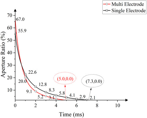
FIGURE 5. Aperture ratio corresponding to arc multi-electrode and single-electrode as a function of time in the pixel closing stage. Each curve consisted of 70 data points with an interval of 0.1 ms. A 15 V boosting voltage was applied to the sub-electrode 4 in the arc multi-electrode, but none at the single-electrode. The oil in the single-electrode was naturally recovered.
Conclusion
In this paper, an arc multi-electrode EWD pixel structure was proposed to improve the display quality, including aperture ratio and response time. To study the performance of electrode structure, a three-dimensional EWD simulation was carried out. The simulation demonstrates the differences in oil motion patterns between two different pixel structures. By dynamically selecting the driving sub-electrode and driving scheme, the arc multi-electrode effectively accelerated the oil movement and improved the pixel response speed. In terms of aperture ratio, the maximum aperture ratio of arc multi-electrode was 11.1% larger than that of single-electrode. In addition, in the pixel closing stage, oil spreading speed can be significantly accelerated by applying a boosting voltage to the sub-electrode corresponding to the oil accumulation area. The arc multi-electrode pixel structure with multiple electrodes design provides a strategy for actively turning off and flexibly turning on the pixel, which theoretically enables it to break through the upper bound on performance of typical EWDs.
Data availability statement
The raw data supporting the conclusions of this article will be made available by the authors, without undue reservation.
Author contributions
SL, LT, SS, DY, and BT: Investigation, methodology, formal analysis, editing. SL: Writing — review, and editing. SL, LT, and SS contributed to the theoretical background and design of the experiments. DY and BT provided theoretical guidance and the funds. All authors contributed to the article and approved the submitted version.
Funding
Supported by the National Key R&D Program of China (2021YFB3600602), Natural Science Foundation of Guangdong Province (No. 2021A1515010623), Science and Technology Program of Guangzhou (No. 2019050001), Program for Guangdong Innovative and Enterpreneurial Teams (No. 2019BT02C241), Program for Chang Jiang Scholars and Innovative Research Teams in Universities (No. IRT_17R40), Guangdong Provincial Key Laboratory of Optical Information Materials and Technology (No. 2017B030301007), Guangzhou Key Laboratory of Electronic Paper Displays Materials and Devices (201705030007) and the 111 Project.
Conflict of interest
The authors declare that the research was conducted in the absence of any commercial or financial relationships that could be construed as a potential conflict of interest.
Publisher’s note
All claims expressed in this article are solely those of the authors and do not necessarily represent those of their affiliated organizations, or those of the publisher, the editors and the reviewers. Any product that may be evaluated in this article, or claim that may be made by its manufacturer, is not guaranteed or endorsed by the publisher.
References
1. Jones TB. An electromechanical interpretation of electrowetting. J Micromech Microeng (2005) 15(6):1184–7. doi:10.1088/0960-1317/15/6/008
2. Bai PF, Hayes RA, Jin ML, Shui LL, Yi ZC, Wang L, et al. Review of paper-like display technologies. Prog Electromagnetics Res (2014) 147:92–113. doi:10.2528/PIER13120405
3. Yi ZC, Feng HQ, Zhou XF, Shui LL. Design of an open electrowetting on dielectric device based on printed circuit board by using a parafilm M. Front Phys (2020) 8:193. doi:10.3389/fphy.2020.00193
4. Feng HQ, Yi ZC, Yang RZ, Qin XF, Shen ST, Zeng WJ, et al. Designing splicing digital microfluidics chips based on polytetrafluoroethylene membrane. Micromachines (2020) 11(12):1067. doi:10.3390/mi11121067
5. Feenstra BJ, Hayes RA, Camps IGJ, Hage LM, Johnson MT, Roques-Carmes T, et al. A video-speed reflective display based on electrowetting: Principle and properties. J Soc Inf Disp (2004) 12(3):293. doi:10.1889/1.1825703
6. Yi ZC, Liu LW, Wang L, Li W, Shui LL, Zhou GF, et al. A driving system for fast and precise gray-scale response based on amplitude-frequency mixed modulation in TFT electrowetting displays. Micromachines (2019) 10(11):732. doi:10.3390/mi10110732
7. Li W, Wang L, Zhang TY, Lai SF, Liu LW, He WY, et al. Driving waveform design with rising gradient and sawtooth wave of electrowetting displays for ultra-low power consumption. Micromachines (2020) 11(2):145. doi:10.3390/mi11020145
8. Yi ZC, Huang ZY, Lai SF, He WY, Wang L, Chi F, et al. Driving waveform design of electrowetting displays based on an exponential function for a stable grayscale and a short driving time. Micromachines (2020) 11(3):313. doi:10.3390/mi11030313
9. Jin ML, Shen ST, Yi ZC, Zhou GF, Shui LL. Optofluid-based reflective displays. Micromachines (2018) 9(4):159. doi:10.3390/mi9040159
10. Chiu Y, Liang C, Chen Y, Lee W, Chen H, Wu S, et al. Accurate-gray-level and quick-response driving methods for high-performance electrowetting displays. J Soc Inf Disp (2011) 19(11):741–8. doi:10.1889/JSID19.11.741
11. Chen YC, Chiu YH, Lee YW, Liang CC. A charge trapping suppression method for quick response electrowetting displays. SID Symp Dig (2010) 41(1):842–5. doi:10.1889/1.3500607
12. Zeng WJ, Yi ZC, Zhao YM, Zeng WB, Ma SM, Zhou XC, et al. Design of driving waveform based on overdriving voltage for shortening response time in electrowetting displays. Front Phys (2021) 9:642682. doi:10.3389/fphy.2021.642682
13. Zhao Q, Tang B, Dong B, Li H, Zhou R, Guo Y, et al. Electrowetting on dielectric: Experimental and model study of oil conductivity on rupture voltage. J Phys D Appl Phys (2018) 51(19):195102. doi:10.1088/1361-6463/aabb69
14. Hong J, Oh JM, Kang KH. Switching time of electrowetting-based Devices. Int Conf Nanochannels, Microchannels, Minichannels (2009) 43499:149–54. doi:10.1115/ICNMM2009-82273
15. Dou YY, Chen L, Li H, Tang B, Henzen A, Zhou GF, et al. Photolithography fabricated spacer arrays offering mechanical strengthening and oil motion control in electrowetting displays. Sensors (2020) 20(2):494. doi:10.3390/s20020494
16. Cahn JW, Hilliard JE. Free energy of a nonuniform system. I. Interfacial free energy. J Chem Phys (1958) 28(2):258–67. doi:10.1063/1.1744102
17. Dolatabadi A, Arzpeyma A, Wood-Adams P, Bhaseen S. A coupled electro-hydrodynamic numerical modeling of droplet actuation by electrowetting. Colloids Surf A: Physicochemical Eng Aspects (2008) 323(1/3):28–35. doi:10.1016/j.colsurfa.2007.12.025
18. Zhou M, Zhao Q, Tang B, Groenewold J, Hayes RA, Zhou GF, et al. Simplified dynamical model for optical response of electrofluidic displays. Displays (2017) 49:26–34. doi:10.1016/j.displa.2017.05.003
19. Yurkiv V, Yarin AL, Mashayek F. Modeling of droplet impact onto polarized and nonpolarized dielectric surfaces. Langmuir (2018) 34(34):10169–80. doi:10.1021/acs.langmuir.8b01443
20. Zhu GP, Yao J, Zhang L, Sun H, Li AF, Shams B, et al. Investigation of the dynamic contact angle using a direct numerical simulation method. Langmuir (2016) 32(45):11736–44. doi:10.1021/acs.langmuir.6b02543
21. Jones TB, Gunji M, Washizu M, Feldman MJ. Dielectrophoretic liquid actuation and nanodroplet formation. J Appl Phys (2001) 89(2):1441–8. doi:10.1063/1.1332799
22. Jones TB, Fowler JD, Chang YS, Kim CJ. Frequency-based relationship of electrowetting and dielectrophoretic liquid microactuation. Langmuir (2003) 19(18):7646–51. doi:10.1021/la0347511
23. Feng HQ, Yi ZC, Sun ZZ, Zeng WJ, Wang L, Yang JJ, et al. A spliceable driving system design for digital microfluidics platform based on indium tin oxide substrate. J Nanoelectronics Optoelectronics (2020) 15(9):1127–36. doi:10.1166/jno.2020.2838
24. Lai SF, Zhong QH, Sun HL. Driving waveform optimization by simulation and numerical analysis for suppressing oil-splitting in electrowetting displays. Front Phys (2021) 9:720515. doi:10.3389/fphy.2021.720515
25. Datta S, Kumar P, Das AK. Manipulation of droplets by electrostatic actuation and the related hydrodynamics. J Indian Inst Sci (2019) 99(1):121–41. doi:10.1007/s41745-019-0101-0
Keywords: electrowetting display, arc multi-electrode, pixel structure, response speed, simulation
Citation: Lai S, Tian L, Shen S, Yuan D and Tang B (2022) An arc multi-electrode pixel structure for improving the response speed of electrowetting displays. Front. Phys. 10:975317. doi: 10.3389/fphy.2022.975317
Received: 22 June 2022; Accepted: 06 July 2022;
Published: 08 August 2022.
Edited by:
Feng Chi, University of Electronic Science and Technology of China, ChinaCopyright © 2022 Lai, Tian, Shen, Yuan and Tang. This is an open-access article distributed under the terms of the Creative Commons Attribution License (CC BY). The use, distribution or reproduction in other forums is permitted, provided the original author(s) and the copyright owner(s) are credited and that the original publication in this journal is cited, in accordance with accepted academic practice. No use, distribution or reproduction is permitted which does not comply with these terms.
*Correspondence: Shitao Shen, c2hlbnNoaXRhb0BtLnNjbnUuZWR1LmNu
 Shufa Lai
 Lixia Tian
 Shitao Shen
 Dong Yuan