- 1Ad Astra Rocket Company Costa Rica, Liberia, Costa Rica
- 2Doctorado en Ciencias Naturales para el Desarrollo (DOCINADE) Program, Instituto Tecnológico de Costa Rica, Universidad Nacional de Costa Rica, Universidad Estatal a Distancia de Costa Rica, San Carlos, Costa Rica
- 3Universidad Nacional de Costa Rica, Heredia, Costa Rica
Helicon plasma sources produce high-density discharges without the need of electrodes in direct contact with the plasma, which is thought to provide them with long operational lifetimes. An explicit steady-state analytical model is described with the capability of depicting the 2D plasma density distribution, the sheath potentials and the estimated sputtering and etch rates along the plasma-facing components of the source. The individual constituting submodels are fitted against available experimental data, and the model is used to predict erosion rates within the VX-CR research helicon plasma source. Erosion within these components is dependent on the value of plasma density along the boundaries, the electron temperature and the particular ion-target material combination. The highest erosion rates are found along the upstream system boundary, followed by the regions near the helicon antenna straps where a capacitive RF sheath is formed. The assumptions and limitations of the model are discussed, and future improvements are proposed.
1 Introduction
The use of helicon plasma sources (HPSs) [1] within different research and practical applications has gained traction because of their ability to produce high-density plasmas at low power levels and magnetic field intensities, and their capability to dissipate energy into the plasma deeper than other technologies such as capacitively-coupled (CC) or inductively-coupled (IC) discharges. Helicon sources have found usage within the materials processing industry, in electric propulsion devices, as ion sources for fusion systems, and within facilities researching the interactions between plasmas and materials at fusion-relevant conditions.
One of the claimed advantages of HPSs is the fact that the discharge is driven by radiofrequency (RF) waves emitted from an external helical antenna which does not contact the plasma directly, thereby discarding any damage to it as a potential failure mode. The erosion of electrodes and grids facing the plasma discharge is one of the key lifetime-limiting factors in practical devices relying on other plasma-generation techniques, and HPSs are therefore expected to exhibit long-lasting operational regimes. The presence of axial magnetic fields within HPSs also contributes to confine the plasma and reduce its diffusion towards the material boundaries. However, the erosion of these internal plasma-facing components due to the contact with the discharge has not been widely investigated in order to accurately estimate its effects. As these sources find their way into ever larger and more powerful devices, clearly understanding their limitations becomes key to the engineering of reliable and robust devices.
In a previous paper [2], we have contributed a review of this topic and the different phenomena involved in its analysis, and described past published work addressing erosion phenomena within HPS. Among those, Berisford et al. [3] conducted experimental measurements of the etching phenomena on the inside of a quartz tube used as dielectric boundary in a helicon source. They identified the voltages induced by the helicon antenna on the inner surface of the HPS dielectric cylindrical boundary as a key erosion mechanism, and correlated their predictions with experimental measurements to within an order of magnitude. Their work relied on simplified formulas for the sputtering of elemental targets by energetic ions and low-frequency RF sheaths, adapted for their particular HPS. Barada et al. [4] and Thakur et al. [5] also confirmed the relevance of this capacitive coupling phenomena in the regions near the location of the antenna straps. Recent work by Beers et al. [6, 7] developed a combined model integrating a finite-element simulation of the RF discharge, an ad-hoc sheath model and a transport code to estimate erosion and deposition rates in high-power deuterium discharges from the Proto-MPEX experiment, which were then compared to experimental measurements. Their approach to sputtering simplified the actual aluminum nitride (AlN) boundaries as pure aluminum, given their observations of aluminum enrichment in the surface after experimental runs. Their simulation provides an accurate and detailed prediction of sheath potentials, sputtering and deposition phenomena, and impurity transport within the HPS; its disadvantage is the complexity involved in the convergence of discrete 3D codes.
In the present work, we describe the development and validation of a modeling tool for the estimation of sputtering and etch rates within the plasma-facing components of a HPS. It combines individual analytical modules for analyzing the 2D distribution of plasma density within the source, the voltages produced by the sheaths in different regimes, and the sputtering phenomena and associated etching. The 2D plasma description and the sheath models adapt fluid-dynamic models previously published in the literature, while the sputtering package is also based on adapted empirical expressions developed to match available experimental data. The sputtering model was extended to provide the ability of simulating compound target materials. The combined model aims to simplify the estimation of average and peak erosion rates within HPSs, with the goal of providing a flexible tool that can be used to predict the performance of a particular device, to develop general erosion mitigation techniques for HPSs in general, and for the engineering analysis of practical helicon implementations.
This paper is organized as follows. Section 2 describes the individual components which form part of the simulation package. Section 3 describes the validation of each individual submodel against publicly-available experimental data sets; as well as the application of the combined tool to a particular HPS, the VX-CR device at Ad Astra Rocket Company Costa Rica. Section 4 analyzes these results and discusses the assumptions and limitations underlying the model, and section 5 summarizes the main findings of this work.
2 Mathematical models
This section describes the first-principle models underlying the implementation of the analysis tools developed for the investigation of erosion phenomena within helicon plasma sources.
Figure 1A) presents an idealized diagram of a helicon plasma source (HPS), showing its main components in a typical cylindrical configuration, as well as the coordinate system defining the simulation domain. Figure 1B), reproduced from [2], describes the two main modes of erosion phenomena within the plasma-facing components of HPSs, as described in the literature.
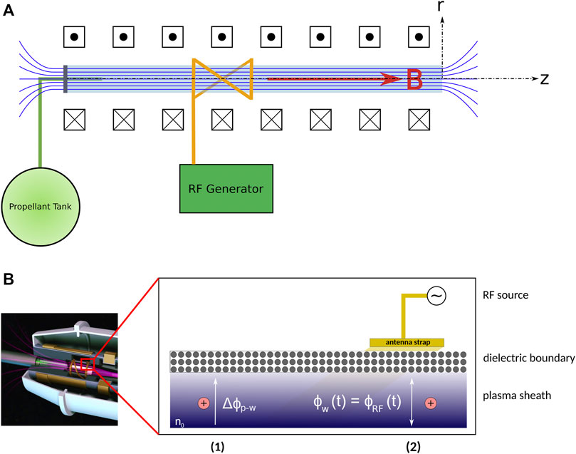
FIGURE 1. (A) A simplified diagram of a Helicon Plasma Source (HPS). (B) A representation of the main mechanisms of erosion present in Helicon Plasma Sources, reproduced from [2]. Region (1) describes the acceleration of ions towards the inner confinement surfaces due to the DC sheath and the floating negative potential present at the surface. Region (2) describes the acceleration of the ions due to the present of an external source of RF excitation, such as the terminals of the antenna used to excite the plasma discharge.
The models presented in the following subsections are independent of the particular ion species present in the plasma, although they do assume the discharge is produced with a single gas (not a mixture of gasees), which is singly-ionized (a typical case in most low-temperature helicon sources).
2.1 Dispersion relation for helicon waves
Helicon waves fall into the category of right-hand polarized (RHP) plasma waves, which propagate along constant magnetic fields in bounded systems. They are related to atmospheric whistler waves, and typically appear in the frequency range ωci ≪ ω ≪ ωce, where ω is the excitation frequency and ωci and ωce are, respectively, the ion and electron cyclotron frequencies for the given configuration.
A description of the relation dispersion describing helicon plasma waves can be obtained from Maxwell’s equations, applying the cold plasma approximation (non-thermal ions) and neglecting the displacement current, as shown in detail by Chen and Arnush [8–10].
When electron inertia is retained in the derivation, the total wave number β of the wave is defined by
where θ is the angle of propagation of the wave with respect to the constant, axial magnetic field
The first solution to Eq. 1, β1, corresponds to the helicon or H mode obtained in the zero electron mass limit, when electron inertia is neglected. Solution β2 corresponds to the Trivelpiece-Gould or TG mode, an electron cyclotron wave propagating at an angle to the magnetic field and a relevant damping mechanism in helicon plasma sources, particularly at low values of B0.
The expression for the H mode β1 can be expanded as
where n0 corresponds to the electron density of the plasma where the wave is propagating, with e the electron charge and μ0 the permeability of free space.
The previous equation provides a means to estimate the maximum value of the expected plasma density for a given helicon device as a function of the axial magnetic field intensity B0, for given values of the excitation frequency ω, the parallel wave number k∥ and the angle θ between the wave propagation vector and B0. These last parameters can be determined through the source’s RF subsystem and the antenna geometry.
For the typical scenario of a helicon plasma source of cylindrical geometry of radius R and exciting mode m = 1, the previous equation can be simplified [8, 11] to
where p0 is the lowest root of the Bessel function of the first kind and order 0 (J1(p0) = 0, with p0 ≈ 3.83).
The actual distribution of plasma density within practical helicon plasma sources is seldom uniform, yet this expression enables the estimation of a reference value for the expected peak plasma density, which can be used with the subsequent models when describing the variation in all relevant plasma parameters.
2.2 2D fluid description of cylindrical magnetized plasmas in steady-state
The description of the plasma behavior within a helicon plasma source is provided by a 2D, two-fluid description of cylindrical plasmas in the presence of an axial magnetic field using the cylindrical coordinate set (r, θ, z). The chosen model is an implementation of the asymptotic magnetized regime proposed by Ahedo and Navarro-Cavallé [12], which describes a quasineutral, isothermal plasma with azimuthal symmetry and where the ion temperature is much lower than the electron temperature, Ti ≪ Te. The model is based in a series of assumptions and simplifications, including: steady-state, azimuthal symmetry, cold neutrals whose velocity un and density distribution nn only depend on the axial position, longitudinal ambipolarity where the axial and radial velocities of ions and electrons are constant (uiz = uez and uir = uer) and the ion azimuthal velocity is negligible uiθ ≪ ueθ = uθ, among others chosen by the authors.
The model is described by a set of radial and axial equations. The radial submodel describes the behavior of the plasma at a given axial location z. The ratio between the plasma density nr and its value at the cylinder axis nr(z, 0) can be described by the expression
where r is the radial coordinate, R is the maximum radius of the cylindrical plasma discharge, nr is the quasineutral plasma density, J0 is the Bessel function of the first kind of order 0 and a0 ≈ 2.405 is the first zero of J0.
The radial component of the ion and electron velocity ur is normalized by the ion sound speed
where the term νe = νen + νei + νion is a linear combination of the electron-neutral νen and electron-ion νei collision frequencies as well as the ionization frequency νion, ωr = cs/R is the radial transit frequency;
The electron azimuthal velocity uθ is normalized by the electron thermal velocity
Boundary conditions for the radial model preclude null plasma velocities and plasma potential ur = uθ = ϕp = 0, and a known plasma density n(z, r) = n(0, r) at the cylinder axis r = 0. At the r = R physical boundary, the Bohm sheath criterion states that ur(z, R) = cs.
The axial submodel describes the plasma parameters at the r = 0 coordinate as a function of the axial coordinate z. For the limit of large Te, large B0 and with ideal plasma recombination at the system physical boundaries (producing neutrals with the same axial velocity un), the ideal asymptotic model from Ahedo et al. [12] can be applied.
The axial neutral velocity un remains constant throughout the source,
The axial velocity of both ions and electrons, uz, is normalized by the ion sound velocity cs and defined in terms of the auxiliary variable ξ as follows
The plasma density n is described by the following expression
where n0 = g0/cs is a reference plasma density, g0 is the axial flow of heavy species (ions + neutrals) at the upstream boundary of the source
The axial neutral density nn is defined as
where nn0 = g0/un0 is a reference neutral density.
The axial variation of the auxiliary variable ξ is defined implicitly by the integral expression
where L is the axial length of the simulation space, L⋆ = cs/(Rionnn0) is an effective ionization mean free path, and Rion is the ionization collision rate. An expressions for Rion as a function of Te is provided in [12].
The boundary conditions for the axial model include the given known values for the following parameters at both the upstream boundary z = −L and the downstream exit plane z = 0: a given value for the flow of neutrals into the system, g0; the reference neutral axial velocity un(r, − L) = un0; and the plasma velocity equal to the Bohm velocity at both the upstream and downstream axial boundaries, uz(r, − L) = −cs and uz(r, 0) = cs. Setting z = 0 and ξ = π/4 in Eq. 11 defines the propellant utilization ηu as an implicit function of the ratio L/L⋆.
2.3 Sheath models
In the region where the plasma contacts a physical material boundary, the quasineutrality of the bulk discharges is broken due to the buildup of charge at the surface. This region is called a sheath, and its properties depend on both the parameters of the plasma as well as the material surface. The scale of the sheath is in the order of the Debye length,
The transition between the bulk plasma and the material surface occurs through different regions or regimes. Prior to the actual sheath, the pre-sheath is located, where the plasma density and potential decrease but quasineutrality is still preserved. At the point where the sheath begins, the Bohm sheath criterion must be met, ui ≥ cs. Within the sheath, quasineutrality breaks and the electron density decreases rapidly towards zero. The potential at the material wall Φw is therefore lower than the bulk plasma.
For the case of a floating dielectric material immersed into the plasma, the potential obtained at the wall can be described [13] as
It is a function of constant properties of the plasma species (the ion and electron masses, mi and me), and the electron temperature Te expressed in units of electric potential. Under the assumption that Ti ≈ 0, ions entering the sheath will be accelerated towards the wall due to the potential difference Φp − Φw, where Φp is the plasma potential.
Other conditions could be present in the boundary material, such as grounded or biased surfaces at a potential Φbias, in which case the analysis would need to take into account the effect of the potential difference Φp − Φbias in the acceleration of the ions.
For the case where radiofrequency (RF) waves are present near the interface of plasmas and materials, such as near the location of the antenna straps providing the excitation source in helicon plasma sources, an RF plasma sheath is created. When the driving RF frequencies are sufficiently high (ωrf ≫ ωpi, with
When the frequency of the RF wave is low enough, ions are able to respond to the RF wave and a low frequency sheath is formed. This condition requires that
The ion energy distribution function gi(E) for a low-frequency RF sheath [13] is given by the expression
where Vrf is the peak voltage amplitude of the RF wave, Vbias is any DC bias voltage applied to the surface, and E is the instantaneous voltage of the RF field. The distribution has a different expression for the case E = Vbias, to take into account the rectifying effect of the low-frequency sheath.
2.4 Sputtering phenomena
Plasma-surface interactions include all the phenomena that appear at the intersection between plasmas and a material boundary. Among those, sputtering is of significant interest to the fields of materials processing, fusion engineering and electric space propulsion. Sputtering is the removal of material from a solid surface due to the impact of energetic particles, and it plays a fundamental role in determining the lifetime of practical devices.
Sputtering depends on several parameters, including the properties of the impinging particles, the composition of the target material surface and the geometry of the impact. A simplified model for the geometry of the sputtering process [2] describes the incoming ion being accelerated by the potential drop on the sheath to an energy E0 until it impacts the surface with an angle θ with respect to the surface normal. If the energy surpasses a threshold level for the occurrence of sputtering, E0 > Ethr, a cascade of collisions within the target material will be able to provide sufficient momentum to one or several particles in the top layer of the target material, and allow them to overcome the surface binding energy Esb and leave the surface.
Sputtering is described by the sputtering yield Y, defined as the number of surface particles sputtered from the target material surface per incoming ion. It depends on the properties of the impacting ion and the target material, the energy of the ion and the angle of incidence. Several models have been developed for the estimation of actual sputtering yields; the model chosen for this study is the one published by Eckstein and Preuss [14], which improves upon earlier work.
The sputtering yield Y when ions impact a surface at normal incidence (θ = 0) is obtained with the expression
It depends on three free parameters (q, λ and μ) used to fit the model to experimental data. Behrisch and Eckstein [15] have tabulated these parameters for a significant selection of sputtering scenarios involving monoatomic elemental targets. The term
which is used as an adequate mean value to describe the nuclear stopping cross section for the problem, for any combination of ion species and target materials (not necessarily involving carbon or krypton). The term ɛ is the reduced potential, which is calculated as
and depends on the parameter aL, the Lindhard screening length,
where aB is the Bohr atomic radius.
When the ion impact occurs at an angle, 0 < θ ≤ π/2, Y can be described by the expression
It depends on the parameters b, c and f, which have also been tabulated in [15] for a variety of common scenarios.
The parameter θ0 is calculated according to the expression
where Esp corresponds to the surface binding energy of the impacting ions; it is equal to the surface binding energy of the projectiles in the case of self bombardment, Esp = 0 for noble gas ions impacting on the target, and Esp ≈ 1 eV for ions of the hydrogen isotopes [14].
2.5 Implementation
The models described in the previous subsections were implemented as an object-oriented (OOP) toolkit in the Python programming language (version 3.9), with extensive use of routines from the NumPy and SciPy packages. The OOP approach enables a modular design, which allows for the substitution of a particular submodel with an alternative version. The approximate running time for the sensitivity analysis simulations presented in Figures 9, 10 is less than 5 min, on a PC computer having quad-core Intel Core i5-5200 CPU at 2.20 GHz, 8 GB of RAM and running the Debian GNU/Linux operating system.
3 Results
3.1 Model validation
In order to adjust the parameters in the models described in Section 2 and to verify the accuracy of their estimations, publicly-available experimental data from a variety of suitable HPSs has been used for comparison. The chosen experimental data sets match the assumptions and configurations required by each submodel, and sufficient detail has been disclosed regarding the relevant physical and geometrical parameters of the source, enabling the use of the different mathematical expressions.
Figure 2 presents the estimations of ne provided by Eq. 3 of Section 2.1 as a function of the axial magnetic field B0, together with experimental data published by Chen [16], Tysk et al. [17] and LaFleur et al. [18]. The parameters obtained for these three validation cases of Figure 2 are listed in Table 1. The chosen data sets are all helicon devices tested with argon gas, using Boswell-type double saddle antennas or half-helical antennas, which preferentially excite wavelengths of twice their lengths, λ ≈ 2 × Lant. The parallel angular wave number k∥ of Eq. 3 is then obtained as k∥ = 2π/λ. This estimation is only an approximation, and Figure 2 shows the range of estimated density values accounting for variations in the wavelength λ of ±50% as suggested by Light and Chen [19]. The linear relationship between n and B0 present in all experimental data sets is closely matched by the model estimations, particularly for the Chen and LaFleur data sets.
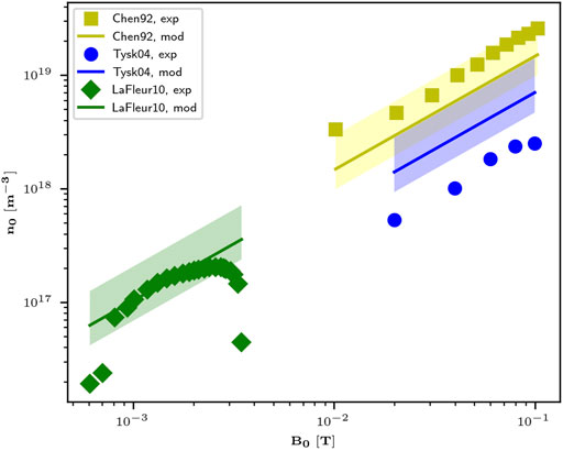
FIGURE 2. Comparison between the estimations provided by the helicon wave dispersion relation of Eq. 1 and experimental data published by Chen ([16]), [17] and [18]. The shaded regions correspond to variations in the estimation of ne when considering the uncertainty in the estimation of λ, taken as ± 50%.
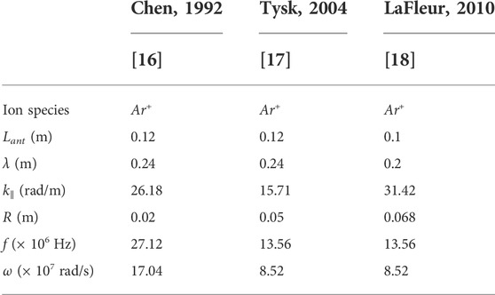
TABLE 1. Experimental parameters obtained for the data sets of Figure 2, used for the validation of the simplified helicon wave dispersion model of Eq. 3.
The two separate fluid-models described in Section 2.2 are compared to experimental measurements in Figures 3, 4. The chosen versions of these models are the asymptotic, magnetized regimes. For the case of the radial model [12, 20], Figure 3 shows the normalized radial profile of the plasma density, compared to experimental data from the CSDX device published by Burin et al. [21], from the VX-CR device by Castro et al. [22] and from the PISCES-RF device by Thakur et al. [5, 23], from experimental runs using argon gas as the feedstock in all cases. The published experimental parameters obtained from these experimental data sets are described in Table 2. The reference plasma density nr0 is obtained from the peak density value at r = 0. In the case of the VX-CR device, the radial coordinates of the published density values in [22] have been adjusted to account for the expansion of the magnetic field lines (and the plasma plume) as they exit the HPS towards the point of measurement. As described by the original authors, the magnetized version of this radial model describes a slow decay of the radial plasma density, which falls rapidly near the radial boundary of the HPS; the experimental data confirms this behavior, with only the VX-CR data approximating the estimated trend. For the purposes of this research, the fact that this magnetized regime of the radial model may overestimate the plasma density near the surface boundary, allows for a more conservative estimation of the boundary etch rates.
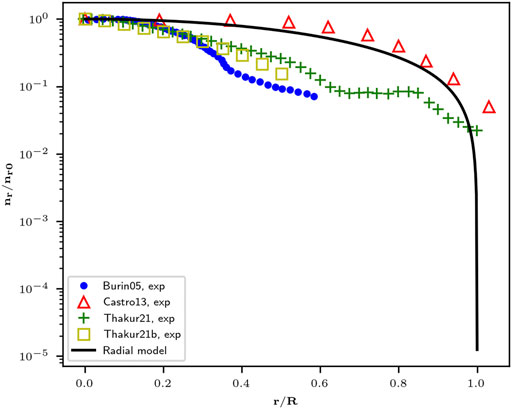
FIGURE 3. Comparison of the radial plasma density distribution estimated by Ahedo’s radial model [12, 20] and experimental data published by Burin et al. [21], Castro et al. [22], and Thakur et al. [5, 23].
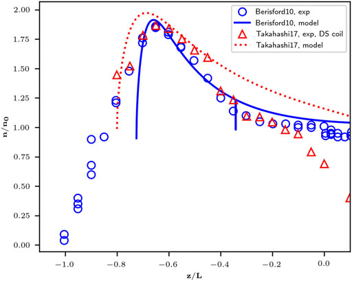
FIGURE 4. Comparison of the distribution of the on-axis plasma density as estimated by Ahedo’s axial model [12] and experimental data published by Berisford et al. [3] and Takahashi et al. [24].

TABLE 2. Experimental parameters obtained for the validation data sets of Figure 3, used for the validation of Ahedo’s radial model in the magnetized case [20, 12], as shown in Eqs 4–6.
The validation of the axial model of Eqs 7–11 with experimental data is presented in Figure 4, where the on-axis plasma density is presented as a function of the axial position inside the cylindrical dielectric containment surface. The experimental data sets are those published by Berisford et al. [3] and Takahashi et al. [24], which once again correspond to experiments running on argon gas. The source parameters used in the estimation are listed in Table 3. It was found that the axial model was able to predict the behavior of the axial density profile, but an axial displacement Δz = zexp − zmod was required to match the experimental data, where zexp and zmod are, respectively, the experimental axial coordinates and the ones used for the model calculations. The reference plasma density n0 is obtained as the asymptotic on-axis density at the downstream boundary of the simulation domain (at the coordinate z = 0 following the convention of [12]). At this location, the Bohm criterion (uz=0 = cs) is imposed as a boundary condition, setting the auxiliary variable ξ = π/4 according to Eq. 8. As the optimization process described for Eq. 11 when z = 0 converges to values ηu → 1 for these two configurations (complete propellant utilization) Eq. 9 will tend towards a maximum value of 2 for the ratio n/n0, which corresponds to the peak on-axis density and can be verified in the experimental data sets.
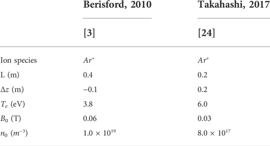
TABLE 3. Experimental parameters obtained for the data sets used in Figure 4, for the validation of Ahedo’s axial model in the asymptotic case [12].
The sputtering model from [14] is compared to experimental data in Figure 5, for the particular case of argon ions impacting SiO2 [13, 25–27], Al2O3 [13, 26] and Si3N4 [25] target materials. The sputtering yield is presented as a function of incident ion energy. These materials were chosen as they are some of the most widely used in the construction of practical HPSs, including the VX-CR device analyzed in the next subsection. Eckstein’s model, as described by Eqs 14–18, is designed to model the interaction between elemental ions and surface materials. The fitting parameters available in the literature for these equations [15] only account for this type of target materials. Therefore, some of the required parameters were obtained by averaging the values of the constituting elements of the compound materials, following a technique originally proposed by Berisford et al. [3] when applying the particular sputtering model presented in [13]. Table 4 lists the parameters chosen to represent these compound materials. The atomic number Zt, the atomic mass mt and the surface binding energy SBEt for each compound target material were found as a simple arithmetic average between the values corresponding to the two constituent elements in the lattice. SBE data was obtained from [13]. The threshold energy, a key parameter in the analysis of low-temperature devices such as typical laboratory HPSs, was selected as the corresponding value for argon atoms in normal incidence on pure Si in the case of SiO2 and Si3N4, and that of pure Al for the case of Al2O3 [15]. The remaining fitting parameters λ, q and μ were obtained through a least-squares optimization algorithm.
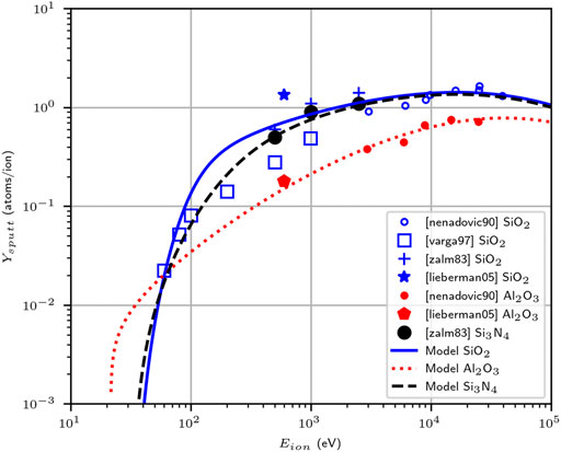
FIGURE 5. Estimation of the sputtering yield at normal incidence for argon ions impacting on different dielectric ceramic materials commonly used in HPSs, obtained from the model presented in Section 2.4. The fitting parameters used are those described in Table 4. The estimations are compared to the available experimental data points published for SiO2 [13, 25–27], Al2O3 [13, 26] and Si3N4 [25].
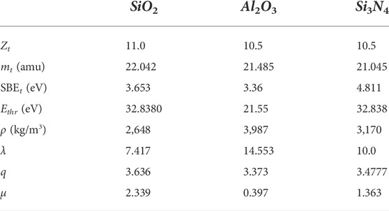
TABLE 4. Fitting parameters chosen to represent SiO2, Al2O3 and Si3N4 within the sputtering estimation models presented in Figure 5. The values for the material properties and the fitting parameters were obtained through a combination of averaging and optimization techniques, as described in subsection 3.1.
3.2 Analysis and investigation of the VX-CR HPS
The VX-CR experiment [22, 28] is a research helicon plasma source (HPS) located at Ad Astra Rocket Company Costa Rica, designed for the study of thermal management and component lifetime issues in the first stage of the VASIMR® [29] engine. Figure 6A shows a simplified diagram of its operating configuration. It consists of a dielectric ceramic cylinder enclosed in a high vacuum chamber with a base pressure of 1.3 × 10⁻⁴ Pa. One end of this cylinder is sealed with a dielectric ceramic endcap, with openings to allow the injection of gas into the HPS. This cylinder is surrounded by a half-wavelength helical copper antenna, driven by an external RF subsystem able to deliver up to 13 kWe of radiofrequency energy to the plasma discharge. The open end of the dielectric cylinder is connected to a 14 m3 exhaust vacuum chamber (not shown in Figure 6), with a baseline pressure of 1.3 × 10⁻¹ Pa. An axial magnetic field is created through two solenoid coils, with the resulting magnetic field intensity profile depicted in Figure 6B. The dielectric boundary surfaces in the VX-CR are at a floating electric potential; this is not always the case for all HPSs, as these elements can be grounded [3] or biased to a particular voltage. Argon is the feedstock gas used in typical operations with the VX-CR and was used in the simulated results described in this subsection.
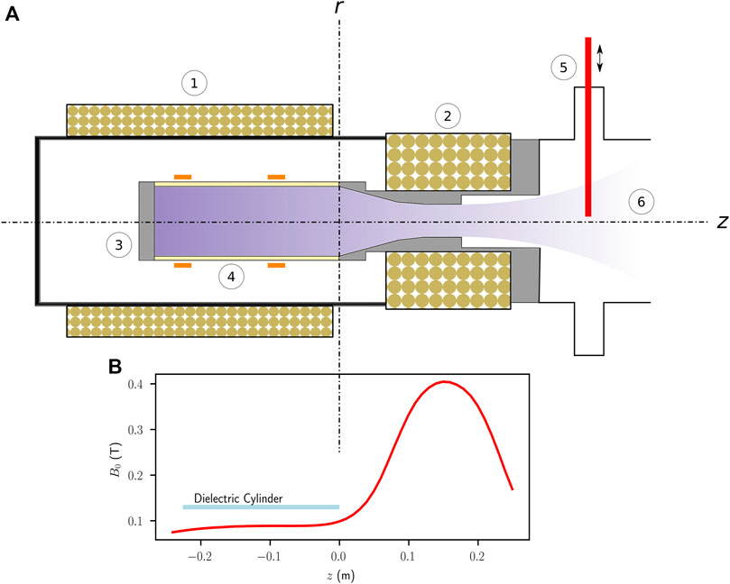
FIGURE 6. (A) Diagram of the VX-CR research helicon device. The axial magnetic field is produced through two solenoid coils, 1 in the HPS region and 2 located downstream of the source. The HPS itself is located inside a high-vacuum chamber to prevent arcing from the voltages present in the RF subsystem. 3 represents the upstream dielectric boundary of the source and this is the point where gas injection occurs (not shown). 4 represents the dielectric cylindrical boundary of the HPS, as well as the approximate location of the helicon antenna straps. 5 marks the location of a reciprocating Langmuir probe used to obtain ion current density and plasma density readings. 6 describes the downstream section of the HPS, interfaced to a vacuum chamber and a pumping system (not shown). (B) Experimental measurements of the magnetic field intensity B0 at the HPS axis as a function of the z axial position. The coordinate system has its origin at the exit boundary of the HPS dielectric cylindrical boundary, following the convention established in section 2.2. Measurement uncertainties for the values of B0 are less or equal than 0.0008 T.
The models described in Section 2 and validated in Section 3.1 were used to estimate the erosion rates due to plasma-material interaction in the VX-CR device. Table 5 shows typical geometrical and operational parameters characteristic of experimental runs at the VX-CR device, at RF power levels between 1 kWe and 4 kWe and using argon gas. The three ceramic materials which have been used for the dielectric components of the device (the cylinder and its boundary endcap) are silicon dioxide (SiO2), alumina (Al2O3) and silicon nitride (Si3N4). Figure 7A presents experimental measurements of the peak RF voltages at the helicon antenna straps as a function of the delivered RF forward power to the system; Figure 7B (adapted from [22]) describes estimations of the electron temperature Te obtained from Langmuir probe data, also as a function of RF forward power.
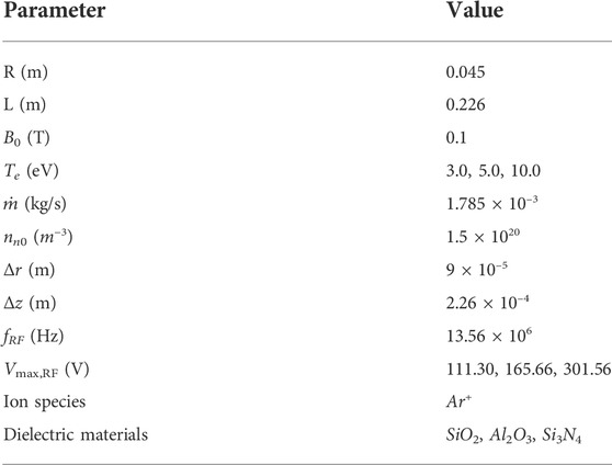
TABLE 5. Geometrical and physical parameters used for the simulation results of the VX-CR device presented in Section 3.2. The values of Te and Vmax,RF correspond to three separate scenarios, and were obtained from the regression described in Figure 7.
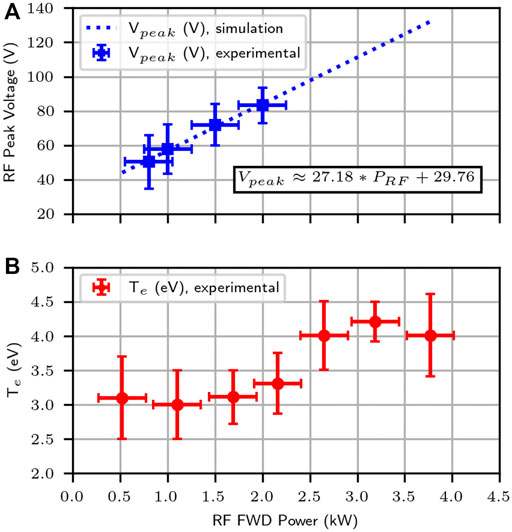
FIGURE 7. Experimental data obtained from the typical operation configuration of the VX-CR helicon plasma source, adapted from [22]. (A) shows the measurements of the peak voltage Vp in the VX-CR helicon antenna, measured at the external RF feed line, as a function of the measured RF forward power coupled into the system. A linear regression has been calculated for these data points, with the resulting expression shown in the plot. (B) shows the estimated values for the electron temperature Te as a function of RF forward power, obtained from measurements with the reciprocating Langmuir probe. Experimental techniques and measurement uncertainties for these data points have been described in [22].
Figure 8 shows the distribution of normalized plasma density inside the VX-CR HPS, as predicted by the models described in Section 2.2 for the scenario with Te = 5 eV. A base density of n0 ≈ 4.04 × 10¹⁸ m−3 is predicted. The maximum estimated plasma density corresponds to nmax ≈ 8.19 × 10¹⁸ m−3, while the mean plasma density is navg ≈ 3.04 × 10¹⁸ m−3.
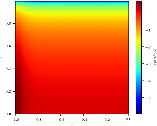
FIGURE 8. Estimated plasma density distribution in the VX-CR device [22, 28], as estimated by Ahedo’s model [12, 20]. The relevant geometrical and physical parameters used for this simulation are listed in Table 5. The reference plasma density n0 is calculated as the ratio of the axial flow rate of heavy species per unit area g0 and the ion Bohm velocity, n0 = g0/cs, and has a value of n0 ≈ 4.04 × 10¹⁸ m−3 in this particular simulation.
The estimated plasma density values shown in Figure 8 were used to obtain the approximate values along the upstream axial
These density estimations along the radial and axial boundaries were used to calculate the etch rates along these surfaces due to the potential created at the wall by the sheath. The electron temperature Te was used as an input to Eq. 12 in order to estimate the potential developed by the inner surfaces, under the assumption that they are floating (isolated from any induced voltages, as is the case in the VX-CR device). Under the cold ion approximation, this potential is taken as the energy obtained by the ions as they traverse the sheath. The sputtering yield was calculated for the case of normal incidence Eq. 14 along the axial and radial boundaries. The etch rate E, defined as the ratio of surface etch depth per unit of time, was calculated through the expression
where Γi = nbuB is the incident ion flux (with nb the plasma density along the boundary), Mm and ρt are the molar mass and mass density of the surface material and NA is Avogadro’s constant.
The results of the etch rate calculations are shown in Figure 9, where etch rate estimations are presented for the axial boundary (Figures A–C) and the radial boundary (Figures D–F). Results are shown for the three different dielectric materials previously analyzed (SiO2, Al2O3 and Si3N4), and three chosen values of the electron temperature. Since the simulation provides the ions with an energy equal to the floating potential obtained by the dielectric walls, the results depend on both Te and the threshold energy for sputtering Ethr in each case. Figure 5 had shown that Al2O3 has a lower threshold energy than SiO2 and Si3N4 according to the sputtering model, and that is the reason why the cases simulating silicon dioxide and silicon nitride present etching only at the higher values of the electron temperature, corresponding to the only scenarios where the wall floating potential produced by the plasma sheath is larger than Ethr. For the scenarios involving aluminum nitride, no sputtering occurs for the cases with Te = 3.0 eV.
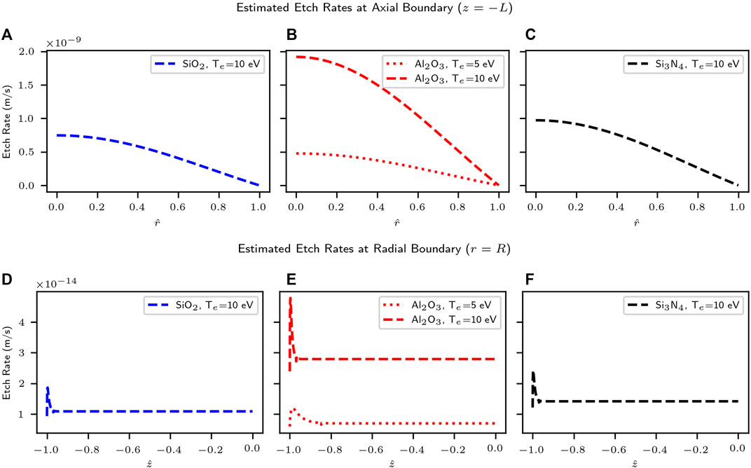
FIGURE 9. Estimated etch rates at the inner surfaces of the boundary dielectric containment material in the VX-CR device, as obtained through the combination of the density distribution, sheath and sputtering models described in Section 2. The etch rates for the axial (z = −L) boundary, the endplate located at the upstream end of the dielectric cylinder, are presented in the top row in plots (A), (B) and (C); the corresponding etch rates for the radial (r = R) boundary, the inner surface of the dielectric cylinder, are presented in the bottom row in plots (D), (E) and (F). Estimations are presented for three different dielectric ceramic materials (SiO2, Al2O3 and Si3N4) and three reference values for the electron temperature Te. Plots are shown only for those scenarios where the ion energies surpass the corresponding threshold energy for sputtering, E0 ≥ Ethr.
The low-frequency RF sheath model from [13], presented in Section 2.3, can be used to estimate the etch rate produced in certain regions of the radial boundary of the dielectric cylinder due to the vicinity of the helicon antenna straps. Table 5 presents the frequency f and peak voltage Vmax,RF present in the helicon antenna straps of the VX-CR device. Using Eq. 13 and assuming that the voltages present in the copper terminals of the antenna are directly induced in the nearby inner surfaces of the dielectric cylinder of the HPS (as suggested by the results presented by [3, 7]), the incident ion energy distribution can be calculated. Once again using the cold ion approximation and assuming the ions are accelerated at normal incident only by the RF sheath voltage, the mean sputtering yield
The average value of the sputtering yield,

FIGURE 10. Estimation of the etch rate at the radial boundary r = R, the inner surface of the dielectric cylinder, due to the low-frequency RF sheath induced by the vicinity of the straps of the helicon antenna, using a method derived from the approach by Berisford et al. [3]. These plots represent the estimated etch rates for all possible locations of these external sources of RF excitation; actual devices typically have these antenna conductors at specific particular locations. Results are presented for three different candidate materials (SiO2, Al2O3, Si3N4 corresponding to plots (A–C)), and three values to of the electron temperature Te.
4 Discussion
4.1 Practical estimation of erosion within HPSs
The analysis of sputtering and erosion phenomena within HPSs is dependent on understanding the behavior of key properties of the plasma throughout the source and particularly in the vicinity of the physical boundary surfaces of interest, with density and temperature being the most relevant parameters. Published experimental results identify two main modes of plasma-material interaction relevant to the estimation of erosion rates in the plasma-facing components of HPSs, which were shown in Figure 1B. Region (1) in the figure describes the acceleration of ions towards the boundary surfaces due to the potential obtained by the floating wall due to the formation of the sheath; the ions will obtain the energy difference between the plasma potential and the wall potential, Δϕp−w = ϕp − ϕw. When using the cold ion approximation, |ϕp|≪|ϕw| is often assumed. This DC sheath is present along all plasma-facing boundary surfaces. Region (2) in the diagram describes the interaction between the ions and the RF sheath produced by the oscillation voltages induced in the vicinity of the location of the helicon antenna straps, dependent on the operation of the RF subsystem external to the HPS. This particular type of sheath, present at specific discrete locations along the radial (r → R) boundary surface, is able to induce potentials ϕRF at the wall typically much larger than those produced by the DC sheath. Practical implementations of HPS commonly rely on RF generators operating in the high-frequency band (6.78 MHz, 13.56 MHz and other typical commercial frequencies), which enable the use of the low-frequency sheath model described in Section 2.3 when the proper conditions are met.
The plasma density profile along the inner surfaces of the dielectric boundaries of a HPS has a direct influence on the magnitude of the rate of erosion throughout these regions, since the incident ion flow rate Γi is directly proportional to nb. In the present approach, the distribution of plasma density has been obtained through the use of the uncoupled models of Section 2.2 for cylindrical geometries, which correspond to the asymptotic limit of the models presented by Ahedo et al. [12]. The radial model Eqs 4–6 produces the classical diffusion profile based on the zero-order Bessel function. Figure 3 shows how the simulated profile tends to overestimate the radial density value as r → R when compared to experimental data, which will produce conservative values of the ion flow rate towards the surface.
The axial model of Eqs 7–11 describes the axial distribution of plasma density along the central axis of the cylindrical geometry, as a function of the reference density n0 = g0/cs obtained from the axial flow rate of ions and/or neutrals
The combination of the models discussed in Section 2 allows for a computationally-inexpensive approximation to sputtering and erosion phenomena within HPSs, as they use uncoupled steady-state fluid expressions for the axial and radial distribution. These are then combined to produce a complete 2D map of the density distribution such as the one in Figure 8. The density decay described by the radial model is combined with the density distribution profile along the cylinder axis provided by the axial model. The values at the cylinder boundaries can then be extracted and used as inputs to the sheath models of Section 2.3, in order to estimate the energy obtained by the ions as they impact the wall. The sputtering models are then used to predict the sputtering yields and corresponding etch rates.
Figures 9, 10 show how the estimated etch rates for the VX-CR device at the axial boundary (the upstream endplate at z → −L) are about four orders of magnitude larger than the ones produced at the radial boundary for either the DC sheath scenario (plots d, e and f of Figure 9) or the low-frequency RF sheath estimation (Figure 10). This is a product of the larger density values present along that boundary surface, which is impacted along the whole range of the radial coordinate 0 < r < R at the axial location z = −L. For the case of the radial boundary (r → R, the inner surface of the dielectric cylinder), the etching produced by the DC sheath potential (Figure 9D–F) is smaller than that produced by the voltages induced by the low-frequency RF sheath (Figure 10). This depends on the particular electrical configuration of the external RF subsystem. In the case of the VX-CR, the RF subsystem is designed to operate at high current levels in order to reduce the voltage magnitude in the RF feed lines. Nevertheless, the average voltages during the negative part of the sinusoidal RF cycle weighted according to the distribution function described in Eq. 13 are larger than those produced by the sheath at the floating walls. For the case of helicon systems with grounded boundary surfaces, the energy of the ions reaching the wall would depend on the magnitude of the plasma potential ϕp and the ion energy distribution function within the plasma, and it is even less likely that the acceleration through the sheath can produce any etching as previously described by Berisford et al. [3].
4.2 Model limitations and potential improvements
The accuracy of the etch rate estimations provided by the model are conditioned by the validity of its assumptions. The simple magnetic field configuration of Figure 1, with a constant axial B0, is not the case for most practical HPS implementations. Devices with discrete solenoid cells might present a cusped profile, while other devices might include regions of higher intensity, mirror configurations and other scenarios. When the magnetic field lines intersect directly with the boundary surfaces, regions of direct impingement will produce localized spots of energy deposition and erosion [6, 7]. Since the radial model chosen is an asymptotic approximation for the magnetized regime, the radial density profile is not dependent on the magnetic field intensity and does not capture the effect of modifying B0 on the radial ion diffusion.
The electron temperature Te is assumed constant, and is an input parameter to both models. It plays a key role in defining the collisional rates and the sheath potentials. A constant Te results from the steady-state condition of the discharge and sufficient electron confinement [20]. This value of Te can be estimated from global input and output parameters of the HPS, such as the total power coupled through the RF subsystem and the particle flow rate through the system boundaries, by using a power balance model (such as the ones described in [12, 30, 31]). This would also enable the use of engineering models of the external RF subsystem for the calculation of the voltages present at the helicon antenna terminals as a function of the coupled RF power. These values could then be used as inputs to the RF sheath models for the estimation of sputtering and etching in the locations near the antenna straps.
The condition of constant axial B0 is rarely accomplished in practical helicon devices with a cylindrical geometry, either because the magnetic field is not produced through a single magnetic cell or due to the deliberate configuration of variable magnetic field intensities with the purpose of producing mirror effects or modifying the performance of the source. If the field lines diverge and intersect the inner surface of the dielectric cylinder, the kinetic energy of the ions along the direction parallel to the field lines is compounded with the acceleration due to the sheath potentials, and significant etching may occur at the impact points [32]. A variable B0 will also produce magnetic field lines which are not parallel to the dielectric cylinder axis at regions near the inner boundary surfaces, and the use of sheath models considering oblique magnetic fields [33] might be necessary.
The presence of a non-parallel magnetic field also contributes to the ions having an impact angle different than normal incidence, requiring the use of the angular sputtering formulas described in Section 2.4 instead of the simpler normal-incidence scenarios used in Figures 9, 10. Another aspect of the sputtering models that needs further research is the lack of accurate experimental data, and therefore the corresponding fitting parameters required by the sputtering expressions, for dielectric ceramic compounds at the low energy ranges typical of HPSs. Parameters such as the threshold energy Ethr play a critical role in the estimation of etching rates, yet most of the available data and models such as the ones in Section 2.4 have been developed in scenarios where ions impact monoatomic targets. The present approach averaged several parameters of Eqs 14–16 between the values corresponding to the constituting elements of the dielectric compounds; however the values for the threshold energy Ethr were obtained from those corresponding to argon ions impacting monoatomic silicon and aluminum, which resulted in the best correlations with published experimental sputtering data.
5 Conclusion
The development and validation of a set of modeling tools designed for the investigation of sputtering and erosion phenomena within the plasma-facing surfaces of a helicon plasma source (HPS) has been presented. It is based on the combination of a 2D fluid-based model for the distribution of plasma density within the HPS (based on the work of Ahedo et al. [12]), sheath models for the estimation of the wall potential in the case of floating surfaces and low-frequency RF fields [13], and a sputtering model based on the work of Eckstein et al. [14]. Relying on the use of steady-state analytical expressions derived from first-principles approximations or empirical models, it aims to provide computationally-inexpensive estimations of the etch rates along the inner boundary surfaces of a HPS. This information is critical for applications of HPSs where long operational times are desired, such as electric propulsion engines or high-power sources for the research of fusion-relevant plasma-material interactions.
The individual components of the model have been validated against published experimental data, centering on the case of argon discharges in sources using silicon dioxide, alumina and silicon nitride components as boundary surfaces. Since the chosen sputtering model was not developed to simulate compound materials, average values were used for the properties of the target material atoms, and the fitting parameters in the model were obtained through an optimization algorithm. The threshold energy for sputtering was selected as that of argon atoms impacting monoatomic silicon or aluminum. This approach yielded the best correlation with published data. This strategy can be adapted to other ion species and target materials, and represents an improvement of previously published techniques using empirical analytical models for the analysis of sputtering on dielectric compound materials such as the approach described in [3]. The subsequent analysis showed how the threshold energy for sputtering Ethr is a critical parameter for the analysis of etching within low-temperature devices such as HPSs.
Estimations of the etch rates due to particle sputtering were obtained for the VX-CR helicon plasma source, as a representative device conforming to the model’s assumptions. The highest expected values were found at the upstream boundary, the circular endcap surface, where etch rates between 0.5 and 2.0 nm/s were obtained due to the acceleration of ions through the sheath at the axial upstream boundary. For the radial boundary (the inner plasma-facing surface of the dielectric cylinder), these values ranged between 0.5 and 5.0 × 10⁻¹⁴ m/s. Along this same boundary surface, etch rates produced by the low-frequency RF sheath acceleration are one order of magnitude higher, with averages between 0.25 and 2.5 × 10⁻¹³ m/s. These results confirm previous findings pointing towards the relevance of the voltages induced by the RF sheath under the antenna straps; but also point towards the importance of controlling the plasma density values in the regions near the upstream axial boundary of the system.
The model presented in this study can potentially be used to guide the physics and engineering design of more robust helicon sources with longer operational lifetime. A discussion is also presented regarding the limitations and possible improvements of this modeling approach, including the estimation of electron temperature from the power balance in the system, the consideration of variable magnetic field intensities and more refined sputtering models for the compounds of interest.
Data availability statement
The original contributions presented in the study are included in the article/Supplementary Material, further inquiries can be directed to the corresponding author.
Author contributions
JDV conceptualized the manuscript and figures, and wrote the first draft of the manuscript. FCD and VG critically revised the manuscript. All authors read and approved the final submitted version of the article.
Funding
This research work was funded by Ad Astra Rocket Company Costa Rica. Financial support for the open-access publishing of this manuscript was provided by the National University of Costa Rica (UNA).
Conflict of interest
Authors JDV and FCD were employed by the company Ad Astra Rocket Company Costa Rica.
The remaining author declares that the research was conducted in the absence of any commercial or financial relationships that could be construed as a potential conflict of interest.
Publisher’s note
All claims expressed in this article are solely those of the authors and do not necessarily represent those of their affiliated organizations, or those of the publisher, the editors and the reviewers. Any product that may be evaluated in this article, or claim that may be made by its manufacturer, is not guaranteed or endorsed by the publisher.
References
1. Chen F. Helicon discharges and sources: a review. Plasma Sourc Sci Technol (2015) 14:014001. doi:10.1088/0963-0252/24/1/014001
2. Del Valle JI, Chang Diaz FR, Granados VH. Plasma-surface interactions within helicon plasma sources. Front Phys (2022) 10:856221. doi:10.3389/fphy.2022.856221
3. Berisford D, Bengston R, Raja L. Power balance and wall erosion measurements in a helicon plasma. Phys Plasmas (2010) 17:033503. doi:10.1063/1.3304184
4. Barada KK, Chattopadhyay P, Ghosh J, Saxena Y, Bora D. Wall charging of a helicon antenna wrapped plasma filled dielectric tube. Phys Plasmas (2015) 22:013507. doi:10.1063/1.4906360
5. Thakur SC, Simmonds MJ, Caneses JF, Chang F, Hollmann EM, Doerner RP, et al. PISCES-RF: A liquid-cooled high-power steady-state helicon plasma device. Plasma Sourc Sci Technol (2021) 30:055014. doi:10.1088/1361-6595/abef19
6. Beers CJ, Green DL, Lau C, Myra J, Rapp J, Younkin TR, et al. RF sheath induced sputtering on Proto-MPEX. I. sheath equivalent dielectric layer for modeling the RF sheath. Phys Plasmas (2021) 28:093503. doi:10.1063/5.0054074
7. Beers C, Lau C, Rapp J, Younkin T, Biewer T, Bigelow T, et al. RF sheath induced sputtering on Proto-MPEX part 2: Impurity transport modeling and experimental comparison. Phys Plasmas (2021) 28:103508. doi:10.1063/5.0065464
9. Chen F, Arnush D. Generalized theory of helicon waves - I - normal modes. Phys Plasmas (1997) 4:3411–21. doi:10.1063/1.872483
10. Arnush D, Chen F. Generalized theory of helicon waves - II - excitation and absorption. Phys Plasmas (1998) 5:1239–54. doi:10.1063/1.872782
11. Chen F. Plasma ionization by helicon waves. Plasma Phys Control Fusion (1991) 33:339–64. doi:10.1088/0741-3335/33/4/006
12. Ahedo E, Navarro-Cavallé J. Helicon thruster plasma modeling: two-dimensional fluiddynamics and propulsive performances. Phys Plasmas (2013) 20:043512. doi:10.1063/1.4798409
13. Lieberman M, Lichtenberg A. Principles of plasma discharges and materials processing. New Jersey: Wiley-Interscience (2005).
14. Eckstein W, Preuss R. New fit formulae for the sputtering yield. J Nucl Mater (2003) 320:209–13. doi:10.1016/s0022-3115(03)00192-2
15.R Behrisch, and W Eckstein, editors. Sputtering by particle bombardment: Experiments and computer calculations from threshold to MeV energies. Berlin, Germany: Springer-Verlag (2007).
16. Chen FF. Experiments on helicon plasma sources. J Vacuum Sci Technol A: Vacuum, Surf Films (1992) 10:1389–401. doi:10.1116/1.578256
17. Tysk S, Denning M, Scharer J, Akhtar K. Optical, wave measurements, and modeling of helicon plasmas for a wide range of magnetic fields. Phys Plasmas (2004) 11:878–87. doi:10.1063/1.1642656
18. Lafleur T, Charles C, Boswell R. Plasma control by modification of helicon wave propagation in low magnetic fields. Phys Plasmas (2010) 17:073508. doi:10.1063/1.3460351
19. Light M, Chen F. Helicon wave excitation with helical antennas. Phys Plasmas (1995) 2:1084–93. doi:10.1063/1.871461
20. Ahedo E. Parametric analysis of a magnetized cylindrical plasma. Phys Plasmas (2009) 16:113503. doi:10.1063/1.3262529
21. Burin M, Tynan G, Antar G, Crocker N, Holland C. On the transition to drift turbulence in a magnetized plasma column. Phys Plasmas (2005) 12:052320. doi:10.1063/1.1889443
22. Castro J, Del Valle J, Arce N, Chinchilla E, Echeverría E, Lezama D, et al. VASIMR VX-CR experiment: Status, diagnostics and plasma plume characterization. In: The 33rd International Electric Propulsion Conference. Washington DC, USA: The George Washington University (2013). IEPC-2013-202.
23. Thakur SC, Paul M, Hollmann E, Lister E, Scime E, Sadhu S, et al. Ion heating in the pisces-rf liquid-cooled high-power, steady-state, helicon plasma device. Plasma Sourc Sci Technol (2021) 30:065010. doi:10.1088/1361-6595/abff10
24. Takahashi K, Ando A. Enhancement of axial momentum lost to the radial wall by the upstream magnetic field in a helicon source. Plasma Phys Control Fusion (2017) 59:054007. doi:10.1088/1361-6587/aa626f
25. Zalm P, Beckers L, Sanders F. On the pole of physical sputtering in reactive ion beam etching. Nucl Instr Methods Phys Res (1983) 209/210:561–5. doi:10.1016/0167-5087(83)90853-0
26. Nenadovic T, Perraillon B, Bogdanov Z, Djordjevic Z, Milic M. Sputtering and surface topography of oxides. Nucl Instr Methods Phys Res Section B: Beam Interactions Mater Atoms (1990) 48:538–43. doi:10.1016/0168-583x(90)90178-w
27. Varga P, Neidhart T, Sporn M, Libiselle G, Schmid M, Aumayr F, et al. Sputter yields of insulators bombarded with hyperthermal multiply charged ions. Phys Scr (1997) T73:307–10. doi:10.1088/0031-8949/1997/t73/100
28. Del Valle JI, Cortés S, Fonseca L, Oguilve-Araya J, Valverde J, Martínez C, et al. The VX-CR experiment: A thermal and lifetime testbed for the VASIMRTM engine. In: 32nd International Electric Propulsion Conference; Wiesbaden, Germany (2011). IEPC-2011-155.
29. Chang Diaz F, Squire JP, Carter M, Corrigan A, Dean L, Farrias J, et al. An overview of the VASIMR® engine. In: 2018 Joint Propulsion Conference; Cincinnati, OH (2018). p. 4416.
30. Lafleur T, Charles C, Boswell R. Electron temperature characterization and power balance in a low magnetic field helicon mode. J Phys D Appl Phys (2011) 44:185204. doi:10.1088/0022-3727/44/18/185204
31. Vidal F, Johnston TW, Margot J, Chaker M, Pauna O. Diffusion modeling of an hf argon plasma discharge in a magnetic field. IEEE Trans Plasma Sci IEEE Nucl Plasma Sci Soc (1999) 27:727–45. doi:10.1109/27.774677
32. Caneses JF, Beers C, Thakur SC, Simmonds MJ, Goulding RH, Lau C, et al. Characterizing the plasma-induced thermal loads on a 200-kW light-ion helicon plasma source via infra-red thermography. Plasma Sourc Sci Technol (2021) 30:075022. doi:10.1088/1361-6595/abf814
Keywords: helicon plasma, erosion, sputtering, model, etching
Citation: Del Valle JI, Granados VH and Chang Díaz FR (2022) Estimation of erosion phenomena within helicon plasma sources through a steady-state explicit analytical model. Front. Phys. 10:950472. doi: 10.3389/fphy.2022.950472
Received: 22 May 2022; Accepted: 05 July 2022;
Published: 11 August 2022.
Edited by:
Jayr Amorim, Instituto de Tecnologia da Aeronáutica (ITA), BrazilReviewed by:
Jon Tomas Gudmundsson, University of Iceland, IcelandUmair Siddiqui, Phase Four, United States
Copyright © 2022 Del Valle , Granados and Chang Díaz. This is an open-access article distributed under the terms of the Creative Commons Attribution License (CC BY). The use, distribution or reproduction in other forums is permitted, provided the original author(s) and the copyright owner(s) are credited and that the original publication in this journal is cited, in accordance with accepted academic practice. No use, distribution or reproduction is permitted which does not comply with these terms.
*Correspondence: Juan I. Del Valle , anVhbkBhZGFzdHJhcm9ja2V0LmNvbQ==
 Juan I. Del Valle
  Víctor H. Granados
  Franklin R. Chang Díaz