 Zhiqiang Zhang
 Kaibin Xue
 Zibin Weng
- 1Science and Technology on High Power Microwave Laboratory, Northwest Institute of Nuclear Technology, Xi’an, China
- 2National Key Laboratory of Antennas and Microwave Technology, Xidian University, Xi’an, China
Due to the power capacity limitation of the rotary joint, mechanical scanning radars are limited to use high-power microwave sources to improve their performance furthermore. To solve this problem, an over-mode circular waveguide rotary joint with radial mutations at the rotation point is introduced in this letter. The structure of the radial mutation is optimized to suppress unwanted modes. By connecting the choke slot and the rotating part, the breakdown risks of the rotary joint can be reduced. In addition, the choke structure is connected to the inner wall of the waveguide with a gap, even the breakdown occurs in the choke, the normal modes inside the waveguide will not be affected. To verify the design, a prototype of the rotary joint is fabricated and measured with the operating band in the range of 9.5–10.5 GHz and a power capacity of 3 GW.
Introduction
Radars play an important role in modern electronic systems [1–3]. The using of high-power microwave sources can effectively improve the detection distance and the anti-interference performance of the radars [4]. As a key device in mechanical scanning radar systems, the rotary joint can ensure a stable transmission of RF signals during the scanning process. There are two main ways to realize the rotary joint, the first one is to use a coaxial structure, and the other is to use a waveguide structure. Usually, waveguide rotary joints based on the waveguide have a higher power capacity, which helps to further improve the power density of the radar systems [5, 6]. But rotary joints in conventional forms generally cannot deal with the GW-level power generated by high-power microwave systems (HPM). To solve this problem, this letter proposes a rotary joint that can operate at 9.5–10.5 GHz with a power capacity of 3 GW level based on over-mode circular waveguide. The joint adopts a non-contact design and a new choke slot structure is designed to improve the power capacity.
Design Principle
Generalized Scattering Matrix Theory
In the uniform direct lossless transmission system, the microwave mode is usually consistent, and once the structure of the waveguide is changed, such as the change of the radius of the circular waveguide or the bending of the axis, the change of the aperture of the rectangular waveguide, etc., the transmission mode in the waveguide will be changed, causing the coupling between the energies of the various modes in the waveguide, which generates new modes.
The generalized scattering matrix theory is used to analyze the abrupt structure in the circular waveguide.
The structure of the two-stage abrupt waveguide is shown in Figure 1.
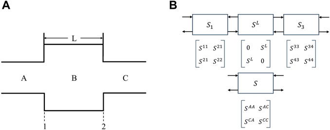
FIGURE 1. Structure and scattering matrix of two-stage abrupt waveguide. (A) Structure of two-stage abrupt waveguide. (B) The scattering matrix of the structure in Figure 1A.
In Figure 1A, B represents a uniform waveguide connecting two abrupt surfaces 1 and 2, which length is L. A and C represent a uniform waveguide connected to B, and they also represent abrupt surfaces 1 and 2.
Figure 1B shows the scattering matrix of the structure of Figure 1A. S1 and S3 represent the scattering matrices at the abrupt surfaces 1 and 2, respectively. S represents the scattering matrix of the two-level abrupt structure, and the superscripts 2 and 3 represent the scattering parameters at the left and right ends of the uniform waveguide B, respectively. The superscripts A and C represent the scattering parameters on the left side of the mutation surface 1 and the right side of the mutation surface 2, respectively, and SL represents the transmission matrix between the mutation surfaces 1 and 2, the definition of SL is as Eq. 1
According to [7–10], the solution of each parameter in S is as follows:
Among Eq. 3, I is the identity matrix, M is the matrix form of Mmn; Yi is the input admittance matrix seen from the ith waveguide to the sudden change;
Choke Structure Design Theory
The choke structure in the rotary joint requires a high microwave transmission efficiency and a high power capacity. A successful design of the choke structure can improve the electric field distribution on the rotating surface, thus reduce the local electric field enhancement and avoid the breakdown. Meanwhile, the rotary joint can be rotated flexibly and the vacuum seal inside the waveguide can be maintained. The choke structure can be analyzed using the microwave equivalent transmission line theory and its equivalent equation is given by Eq. 4:
Where
so
When
Minimum voltage occurs on the inner wall of the choke, so the breakdown problem can be effectively avoided.
Geometry and Design
The rotary joint includes three parts: circular waveguides, a choke structure and a sealing structure. The two ends of the joint are the input and output ports respectively. Its geometry structure is shown in Figure 2. The radii of fillets 1 and 2 are 5 and 0.3 mm respectively.
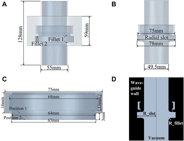
FIGURE 2. The geometry structure of the rotary joint. (A) Front view of the external of waveguide. (B) Front view of the internal of waveguide. (C) Front view of the choke slot. (D) The sectional view of the waveguide.
Design of the Circular Waveguide
Conventional circular waveguides have a small power capacity, and if they are used in the HPW system, breakdown will occur inside the waveguide. The over-mode waveguide is a waveguide whose size is larger than the traditional waveguide size at the operating frequencies, which can withstand a higher power due to its increased sectional area [11–14]. The field distribution in the rotary joint must have the characteristics of axisymmetric distribution to ensure stable output in the continuous rotation process. The field distribution of the TM01 mode is axisymmetric, and the phase is stable, so TM01 mode is used as the operating mode in this rotary joint. The designed rotary joint is excited by TM01 mode, which also requires the use of an over-mode circular waveguide.
Design of the Choke Structure
Since it needs a certain space to rotate itself for the rotary joint, a slot is made in the waveguide wall along the radial direction as shown in Figure 2. However, a discontinuity in the radial direction of the waveguide in introduced, and can excite high-order modes in the waveguide. Figure 3 shows Simulated S21 for each transmission mode in rotary joint when the radial slot has a radius of 39 mm, a length of 12 and 5 mm fillets for the connections. It can be seen with the introducing of the discontinuous structure exists in the rotating joint, when the TM01 mode generated, some additional modes, such as TE11, TE21, TM11, TE31, TE01, and TM21 are also excited.
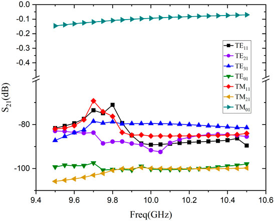
FIGURE 3. Simulated S21 for each transmission mode in rotary joint.
As shown in the Figure 3 except for the TM01 mode, the S21 of TE11, TM11, and TE31 are larger than other high-order modes, so they are selected as the analysis objects later.
As shown in Figure 4, Figure 5 and Figure 6, the optimization of fillet radius R_fillet of the waveguide radial slot, slot radius R_slot and slot length L_slot can suppress higher-order modes.
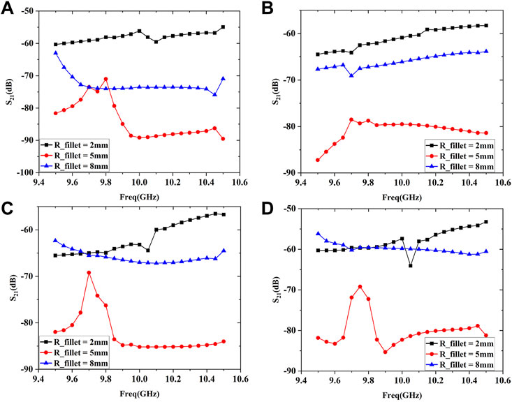
FIGURE 4. Influence of radial slot fillet radius on coupled mode transmission. (A) TE11 mode. (B) TM11 mode. (C) TE31 mode. (D) Sum of TE11, TM11 and TE31 mode.
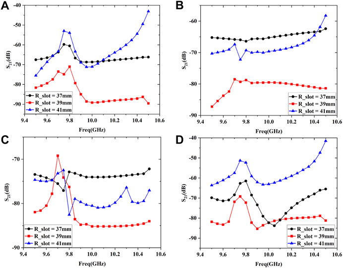
FIGURE 5. Influence of radial slot radius on coupled mode transmission. (A) TE11 mode. (B) TM11 mode. (C) TE31 mode. (D) Sum of TE11, TM11 and TE31 mode.
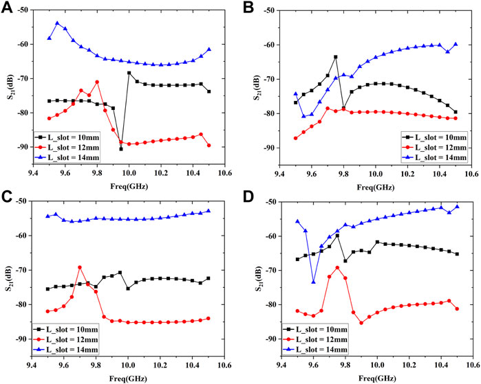
FIGURE 6. Influence of radial slot length on coupled mode transmission. (A) TE11 mode. (B) TM11 mode. (C) TE31 mode. (D) Sum of TE11, TM11 and TE31 mode.
It can be seen that the suppression of the unwanted modes is achieved when the radius and the length of the radial slot are chosen to be 39 and 12 mm, respectively.
It can be derived from the choke theory in Eq. 7, when the choke slot length is 15 mm, 1/2λ, the voltage is minimized at the point where it is connected to the inner wall of the waveguide. It is helpful to avoid the breakdown problem. After optimization, the choke slot length is adjusted to 17 mm, as shown in Figure 2.c. It can be seen that the choke slot is not directly connected to the inner wall of the waveguide, but is connected to the slot along the radial direction. The field strength is relatively small and the risk of breakdown is smaller than choke slot which is connected to the inner wall. Since the choke slot is not directly connected to the inner wall of the waveguide, when the choke slot is broken down, the influence of the electric field in the waveguide is relatively weak.
According to the measurement, the breakdown field strength of YL122 aluminum alloy material is 700 kv/cm. Figure 7 shows the field strength distribution of the inner of the waveguide when the input energy is 3 GW. It can be seen that the field strength at the location of the choke slot is about 600 kv/cm, so this rotary joint can withstand 3 GW microwave power.
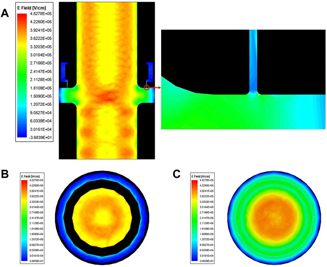
FIGURE 7. Field strength distribution on the inner of the waveguide. (A) The sectional view of field strength distribution inside the waveguide. (B) Position 1 view of field strength distribution inside the waveguide. (C) Position 2 view of field strength distribution inside the waveguide.
Measurement Results
Figure 8 is the photograph of the rotary joint. When the rotary joint is operating in TM01 mode, and the measured and simulated results of the transmission coefficient and the standing wave ratio are shown in Figure 9.
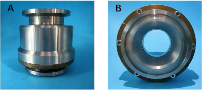
FIGURE 8. Photo of the rotary joint. (A) The front view of the rotary joint. (B) The bottom view of the rotary joint.
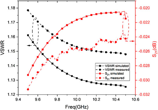
FIGURE 9. S21 and VSWR of TM01 mode.
A HPM source [15–17] and horn antenna are used for the power capacity measurements of the rotary joint. The HPM source has a microwave pulse width of 20 ns and a output power of 3 GW. The horn antenna is a multimode conical horn with continuously variable flare angle. In the experiment, the rotary joint is connected between the HPM source and the horn antenna, and the power capacity of the rotary joint is evaluated by monitoring whether the microwave waveform of the radiation field shows tail-erosion phenomenon to determine whether the breakdown occurs during the transmission process. Figure 10 shows the radiation field waveform when 30 microwave pulses are continuously input to the rotary joint in the measurement. The vacuum value during the high-power test is 3∗10−2Pa.

FIGURE 10. The output waveform of pulse width 20 ns for X-band.
The comparison between the online waveform and the radiation field waveform in Figure 9 shows that the waveform repetition is very well and there is no tail erosion, which indicating that there is no obvious HPM breakdown in this rotary joint. As a result, the power capacity of this rotary joint meets the demand of HPM with power of 3 GW and microwave pulse width of 20 ns.
Conclusion
In this paper, a high-power radar rotary joint is designed based on an over-mode circular waveguide, and an innovative choke slot is used, which reduces the electric field strength at the choke slot and reduces the risks of the breakdown. The structure of the radial slot is optimized to suppress other coupling modes, and the transmission efficiency of TM01 mode at 9.5–10.5 GHz reaches more than 98.9% while withstanding power of 3 GW.
Data Availability Statement
The raw data supporting the conclusion of this article will be made available by the authors, without undue reservation.
Author Contributions
All authors listed have made a substantial, direct, and intellectual contribution to the work and approved it for publication.
Conflict of Interest
The authors declare that the research was conducted in the absence of any commercial or financial relationships that could be construed as a potential conflict of interest.
Publisher’s Note
All claims expressed in this article are solely those of the authors and do not necessarily represent those of their affiliated organizations, or those of the publisher, the editors and the reviewers. Any product that may be evaluated in this article, or claim that may be made by its manufacturer, is not guaranteed or endorsed by the publisher.
References
1. Roarty H, Cook T, Hazard L, George D, Harlan J, Cosoli S, et al. The Global High Frequency Radar Network. Front Mar Sci (2019) 6:164. doi:10.3389/FMARS.2019.00164
2. Yao H, Liu X, Zhu H, Li H, Dong G, Bi K. Dual-band Microstrip Antenna Based on Polarization Conversion Metasurface Structure. Front Phys (2020) 8:279. doi:10.3389/FPHY.2020.00279
3. Sharma A, Chaudhary S, Malhotra J, Saadi M, Al Otaibi S, Nebhen J, et al. A Cost-Effective Photonic Radar under Adverse Weather Conditions for Autonomous Vehicles by Incorporating a Frequency-Modulated Direct Detection Scheme. Front Phys (2021) 9:467. doi:10.3389/FPHY.2021.747598
4. Zhang J, Jin ZX, Yang JH, Zhong HH, Shu T, Zhang JD, et al. Recent advance in Long-Pulse HPM Sources with Repetitive Operation in S-, C-, and X-Bands. IEEE Trans Plasma Sci (2011) 39(6):1438–45. doi:10.1109/TPS.2011.2129536
5. Hamamah F, Ahmad WFHW, Gomes C, Isa MM, Homam MJ. High Power Microwave Devices: Development since 1880. In: 2017 IEEE Asia Pacific Microwave Conference (APMC) (2017). p. 825–8. doi:10.1109/APMC.2017.8251576
6. Chang TH, Yu BR. High-power Millimeter-Wave Rotary Joint for Radar Applications. In: 34th Internatinal Conference on Infrared, Millimeter, and Terahertz Waves (2009). p. 1–2. doi:10.1109/ICIMW.2009.5325680
7. Moran-Lopez A, Corcoles J, Ruiz-Cruz JA, Montejo-Garai JR, Rebollar JM. Generalized Scattering Matrix of the Discontinuity between an Equilateral Triangular Waveguide and a Rectangular, Circular or Elliptical Waveguide. In: 2016 Asia-Pacific Microwave Conference (APMC) (2016). p. 1–4. doi:10.1109/APMC.2016.7931283
8. Gesell G, Ciric IR. Scattering from Double Discontinuities in Circular Waveguides. IEEE Antennas Propagation Soc Int Symp (1992) 4:2126–9. doi:10.1109/APS.1992.221446
9. Kreczkowski A, Mrozowski M. Multimode Analysis of Waveguide Discontinuities Using the Concept of Generalised Scattering Matrix and Power Waves. In: 13th International Conference on Microwaves, Radar and Wireless Communications. MIKON - 2000. Conference Proceedings (IEEE Cat. No.00EX428) (2000). p. 569–72. doi:10.1109/MIKON.2000.913997
10. Bornemann J, Hesari SS. Scattering Matrix Subtraction Technique for Mode-Matching Analysis of Substrate Integrated Waveguide Junctions. In: 2017 IEEE MTT-S Int Conf Numer Electromagn Multiphysics Model Optimization RF, Microwave, Terahertz Appl (2017). p. 1–3. doi:10.1109/NEMO.2017.7964167
11. Yuan CW, Zhong HH, Qian BL. Design of bend Circular Waveguides for High-Power Microwave Applications. High Power Laser Part Beams (2009) 2009:255–9. doi:10.1360/972009-1551
12. Yan J, Wang J, Hao W, Cui X, Liu Y, Zhu X, et al. A Method for Accurately Characterizing Single Overmoded Circular TM01-TE11 Mode Converter. IEEE Access (2020) 8:113383–91. doi:10.1109/ACCESS.2020.3002501
13. Cui X, Wang G, Jiang T, Shao H, Sun J, Wu X, et al. High-efficiency, Broadband Converter from a Rectangular Waveguide TE10 Mode to a Circular Waveguide TM01 Mode for Overmoded Device Measurement. IEEE Access (2018) 6:14996–5003. doi:10.1109/ACCESS.2018.2815530
14. Jiawei Li J, Huijun Huang H, Zhiqiang Zhang Z, Wei Song W, Hao Shao H, Changhua Chen C, et al. A Novel X-Band Diplexer Based on Overmoded Circular Waveguides for High-Power Microwaves. IEEE Trans Plasma Sci (2013) 41(10):2724–8. doi:10.1109/TPS.2013.2258473
15. Changhua Chen C, Guozhi Liu G, Wenhua Huang W, Zhimin Song Z, Juping Fan J, Hongjun Wang H. A Repetitive X-Band Relativistic Backward-Wave Oscillator. IEEE Trans Plasma Sci (2002) 30(3):1108–11. doi:10.1109/TPS.2002.801656
16. Mahto M, Jain PK. Design and Simulation Study of the HPM Oscillator-Reltron. IEEE Trans Plasma Sci (2016) 44(5):743–8. doi:10.1109/TPS.2016.2543305
Keywords: high power microwave, rotary joint, circular waveguide, generalized scattering matrix, discontinuous waveguide
Citation: Zhang Z, Xue K and Weng Z (2022) A High-Power Radar Rotary Joint. Front. Phys. 10:948570. doi: 10.3389/fphy.2022.948570
Received: 20 May 2022; Accepted: 06 June 2022;
Published: 28 June 2022.
Edited by:
Zhen Liao, Hangzhou Dianzi University, ChinaReviewed by:
Hao Li, University of Electronic Science and Technology of China, ChinaZhang Zhonghai, Hangzhou Dianzi University, China
Copyright © 2022 Zhang, Xue and Weng. This is an open-access article distributed under the terms of the Creative Commons Attribution License (CC BY). The use, distribution or reproduction in other forums is permitted, provided the original author(s) and the copyright owner(s) are credited and that the original publication in this journal is cited, in accordance with accepted academic practice. No use, distribution or reproduction is permitted which does not comply with these terms.
*Correspondence: Kaibin Xue, a2J4dWVAc3R1LnhpZGlhbi5lZHUuY24=