 Qurrat Ul Ain
 Y. Khan2*
 Rashid Mahmood
 Afraz Hussain Majeed
- 1Department of Mathematics, Air University, Islamabad, Pakistan
- 2Department of Mathematics, University of Hafr Al Batin, Hafr Al Batin, Saudi Arabia
- 3International Cultural Exchange School, Donghua University, Shanghai, China
Hydrodynamic forces are crucial in engineering applications; therefore, various research initiatives have been conducted to limit them. In this research, a passive control technique to investigate the fluid forces acting on a circular cylinder in a laminar flow regime is studied. The reliability of the usage of a splitter plate (passive control device) downstream of the obstacle in suppressing the fluid forces on a circular obstacle of diameter
Introduction
During the last decade or so, the subject of flow control has received considerable attention and is an evolving field of fluid dynamics. The flow wake behind the bluff structure can induce unsteady forces, which have the power to ruin the structure in contact with the flow field. At the same time, a small change in the configuration can lead to large engineering benefits, such as drag reduction, lift enhancement, or mixing enhancement. Often CFD simulation aims to control the fluid forces acting on the obstacles.
Flow control is an intriguing area with numerous real-world applications, especially in aerodynamics. When an uneven wake emerges behind an obstruction, it creates structural oscillations that might induce fatigue failure. Controlling the wake phenomenon could directly serve an extensive range of engineering applications, such as skyscrapers, bridges, naval risers, columns, and just a few segments of airplanes. The downstream flow regime is mostly determined by the bluff object’s configuration and the inflow velocity (or the Reynolds number, Re). In the downstream wake zone, isolated shear layers from both upper and lower regions of the bluff item lift up above a critical
The use of a splitter plate located in the bluff body wake has gained substantial attention in the past as a passive control solution because of its simple geometric structure. The splitter plate’s ability to reduce wake was developed in early experimental investigations conducted by Roshko in the mid-1950s [4, 5]. At Re = 14,500, he revealed that a plate with a length of 5D (where D is the cylinder diameter) affixed to the cylinder base could entirely control vortex shedding. Because of the splitter plate, the base pressure was increased, whereas the drag force was reduced. [6] investigated the wake flow behind a two-dimensional bluff body model with a wake splitter plate with a base/height ratio of up to 4. The influence of the splitter plate on the frequency of vortex shedding was explained by [7] in the context of the frequency-determining factors in the vortex formation zone and the shear layer diffusion length. By monitoring the pressure distribution, the vortex shedding frequency, and the flow visualizations, [8]and [9] investigated the effect of the splitter plate on the flow characteristics.
A significant parameter is a nondimensional gap from the base point of the cylinder to the splitter’s forefront that determines the wake behavior, according to experiments on the detached splitter plate [10]. They discovered that the wake–plate interactions significantly influenced the intensity of absolute instability in the mean flow. [11] evaluated the impact of a detachable plate on a circular obstacle and found that forces induced on the cylinder were significantly lessened. [12] investigated the impact of a splitter plate not attached to the cylinder in an asymmetric arrangement on the length and position of the plate. He noticed that as the distance between the cylinder’s central point and the forefront of the downstream splitting plate was increased, the drag coefficient began to decrease. By altering the position of the splitter plate, [13] broadened the prior experimental research to evaluate the impact of a splitter plate with some gap separation on the abolishment of vortex shedding. [14] hypothesized that removing or decreasing the local absolute unsteadiness in the separated shear layers and wake centerline section could result in substantial control over Von-Karman vortex shedding and a decrease in unstable forces. [15] investigated detachable splitting plates and discovered a considerable reliance on high Reynolds numbers.
It has been reported by [16] that the drag coefficient of the attached type rigid splitter plate reduces monotonically as the length of the plate increases up to twice the circular-shaped cylinder’s diameter. The length of the stiff splitter for which the vortex shedding phenomena is obstructed for flow through a circular cylinder is the subject of another investigation by [17]. In recent years, an experimental study by [18]has been conducted on a wind tunnel. They investigated the impact of various gaps between adjacent passive jet rings for controlling the VIV. To investigate the plate length’s sensitivity, [19] provided an upstream splitter plate to the stagnation point of a circular cylinder. They concluded that the reduction in the mean drag and fluctuating lift could reach 36.0% and 63.6%, respectively, when L/D was equal to 1.0. To envisage the VIV response of a cylinder of circular shape immersed in a fluid, [20] established a coupled wake oscillator dynamic equation.
The viscous flow around obstructions was initially considered, but non-Newtonian fluids have made a huge impact as a result of technological advances across the industrial frontiers in the last few decades as obvious from the literature [21–23]. Non-Newtonian fluids are even further classified into many classes. There is only a minor contribution to non-Newtonian fluids flowing around obstacles in the literature. From the literature [24–27], one can evaluate contemporary and historical achievements using both Newtonian and non-Newtonian fluid models. The study is limited to one of the non-Newtonian fluids known as the power-law or Ostwald–de Waele fluid in this endeavor. Because of the power-law fluid model’s relevance, numerous scholars have applied their findings to other geometrical configurations [28–30]. Power-law fluids have been the subject of an unceasing stream of research in recent years.
Control of hydrodynamic forces using splitter plates has been done mostly for Newtonian fluids; however, for non-Newtonian fluid models, much more work is required as most of the fluids of practical interest possess nonlinear viscosity. The novelty of the present work is that it examines the influence of a splitter plate for the minimization of drag force on a circular cylinder for non-Newtonian fluid in a transient flow by using the power-law model. An initial study is for viscous flow by analyzing the effects of a control splitter plate fitted to an obstacle of circular shape on the reduction of drag and enhancement of lift coefficients, at
The current work is divided into numerous categories and organized as follows. The description of physical problems and the governing equations with fundamental relations are explained in the first and second sections. The third section consists of the description of the numerical scheme and grid convergence. Moreover, for code validation, the results are compared with the literature [33]. The results and discussion of the present paper are provided in the fourth section. The conclusions of this present study are presented in the last section.
2 Physical Problem and Mathematical Modeling
Two problems considered in this section are associated with the laminar flow around a circular cylinder with an attached splitter plate of different lengths (Figure 1) and the laminar flow around a circular cylinder fitted with a splitter plate of various gap separation in a channel (Figure 2). A channel of height H = 0.41 m and length L = 2.2 m be the dimension of physical domain with a circular cylinder of diameter D = 0.1 m and centre C(0.2,0.2). In the case of splitter plate attached to the surface of the cylinder, plates of different lengths

FIGURE 1. Schematic diagram, when a splitter of length
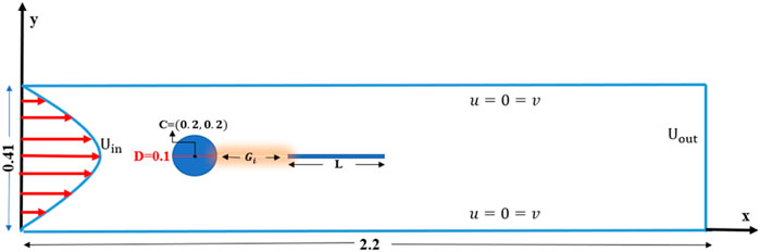
FIGURE 2. Schematic diagram, when a splitter of length
For nondimensionalized governing equations, the average velocity
For the purposes of analysis, the results have been computed as follows:
• The characteristics of transient flow for Newtonian fluid are studied.
• The features of transient fluid flow for non-Newtonian fluid are also investigated.
• The impact of parabolic inlet flow is carried out while ignoring the impacts of body forces.
• The boundary condition, i.e., no-slip condition, is imposed on the surface of the cylinder and splitter plates as well as on both symmetric channel walls.
For a viscous, incompressible fluid in a transient flow over a circular obstacle along with an attached or detached splitter plate, the governing equations are the continuity and momentum equations. The governing equations in the dimensionless form are written as follows:
The shear stress relation for viscous fluids is as follows:
Where
For non-Newtonian power-law fluid,
where
For
For the transient flow field, the boundary conditions are described as follows:
Inlet boundary
Outlet boundary
Side walls
Cylindrical surface
The dimensionless parameter Reynolds number
where
At the postprocessing stage, we have deduced the quantities of interest described as follows:
• Drag coefficient
• Lift coefficient
The nondimensional drag
3 Numerical Procedure
FEM computation is used to achieve and handle a mathematical formulation of governing Eqs 1–3. The stable finite element pair
3.1 Weak Formulation
The basic mechanism for solving the system of Eqs 1–3 is the finite element method. The initial step is the conversion of Eqs 1–3 into what is known as “weak formulations.” We begin by introducing test and trial spaces, as follows:
Let
In Eqs 6–8,
Using the finite-dimensional subspaces, we compute continuous solutions with discrete ones for numerical approximation.
Using Eq. 9 in Eqs 6–8, the following discrete version is obtained:
Basis functions are defined for discrete solutions as follows:
where
In the matrix form,
Here,
3.2 Validation of Results
The legitimacy of the numerical results must be established because the current numerical study is conducted using a CFD program based on the PARDISO solver. For authentication of the present numerical investigation, the drag coefficient
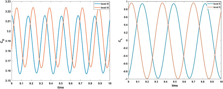
FIGURE 3. Drag and lift comparison tests for periodic flow at

TABLE 1. Comparison between the present results and the available in the literature for the problem with a bare cylinder.
3.3 Grid Independence Test
Figure 4 demonstrates the computational domain that is meshed using the elements of triangular and quadrilateral shapes. Because of the velocity gradient’s high value, the quadrilateral elements were used close to these areas near the wall of the cylinder and the edges of the splitter plate. Moreover, triangular elements were used for the remaining computational domain. The test for grid independence was conducted on the flow past the circular cylinder with an attached splitter plate of length
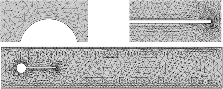
FIGURE 4. Hybrid mesh grid detail.

TABLE 2. Test for grid independence using an attached splitter plate to the circular cylinder.
4 Results and Discussion
The numerical solutions to dimensionless Eqs 1–3 at
4.1 Effects of Newtonian Fluid
Figures 5, 6A–C are velocity profiles for the case when the splitter plate is attached to the circular cylinder and for a detached splitter plate, respectively. The fluid begins to flow in a channel with a parabolic velocity profile as an inlet velocity, and at a right angle, the region showing the stagnation point is formed to the flow direction, so that the fluid bifurcates about the cylinder with greater velocity, whereas the fluid so close to the side walls admits minimum velocity or zero velocity because of the no-slip condition. For case
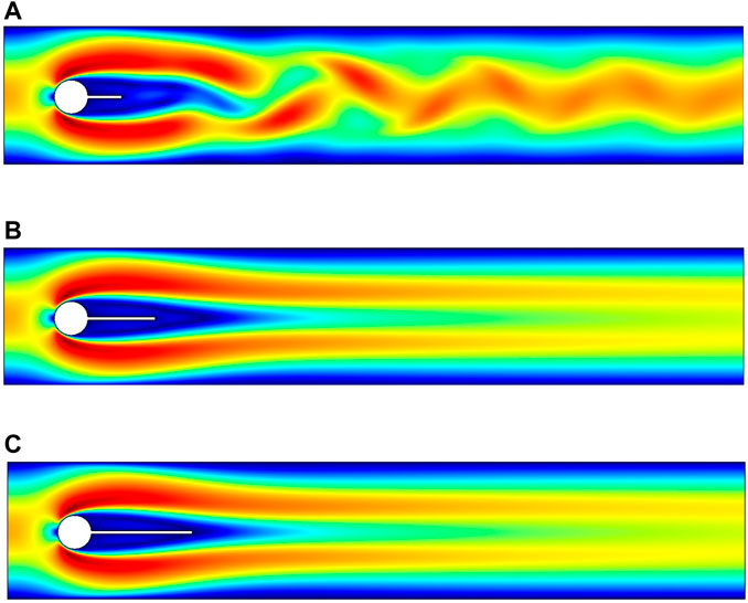
FIGURE 5. Influence of an attached splitter plate on velocity, of length (A) L1 = 0.1, (B) L2 = 0.2, (C) L3 = 0.3 with
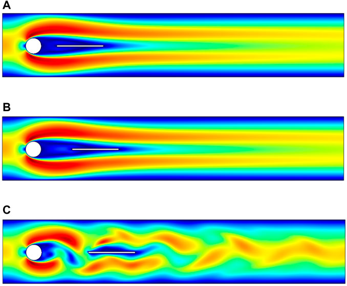
FIGURE 6. Influence of splitter plate with various gap separation on velocity, placed at gaps (A) G1 = 0.1, (B) G2 = 0.2, (C) G3 = 0.3 with
The flow visualizations for fluid motion are shown in this section. Figures 7A–C illustrate the total pressure for various splitter plate lengths, and Figures 8A–C show the splitter plate of fixed length fitted at various gap separations, respectively. The pressure is maximum at the stagnation point and becomes minimum when fluid bifurcates around the circular obstacle. For the first case, each figure shows the effects of the splitter plate’s length variation from
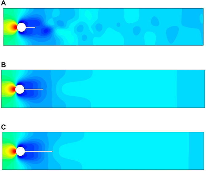
FIGURE 7. Influence of attached splitter plates on pressure, of length (A) L1 = 0.1, (B) L2 = 0.2, (C) L3 = 0.3 with

FIGURE 8. Influence of detached splitter plate (length
The drag and lift forces are induced here in a channel flow because of the presence of an obstacle of circular shape centered at
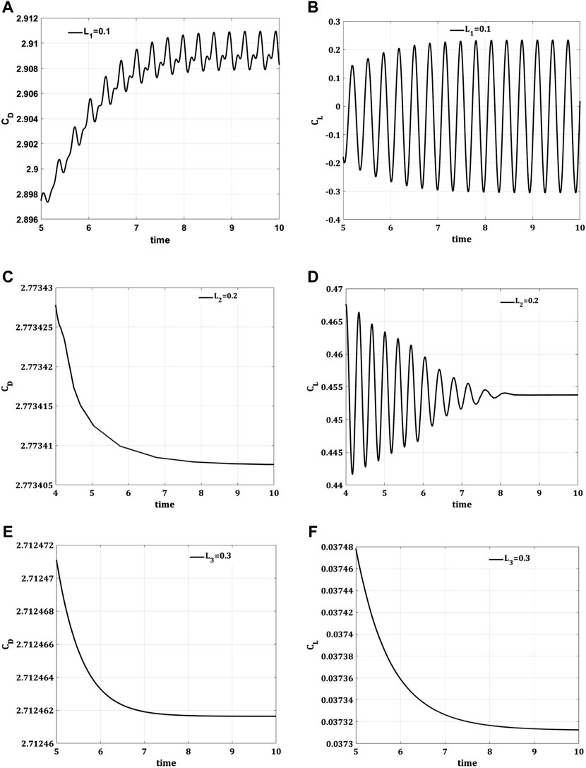
FIGURE 9. Impact of an attached splitter plate of length (A,B) L1 = 0.1, (C,D) L2 = 0.2, (E,F) L3 = 0.3 on drag coefficient (CD) and lift coefficient (CL) w.r.t time
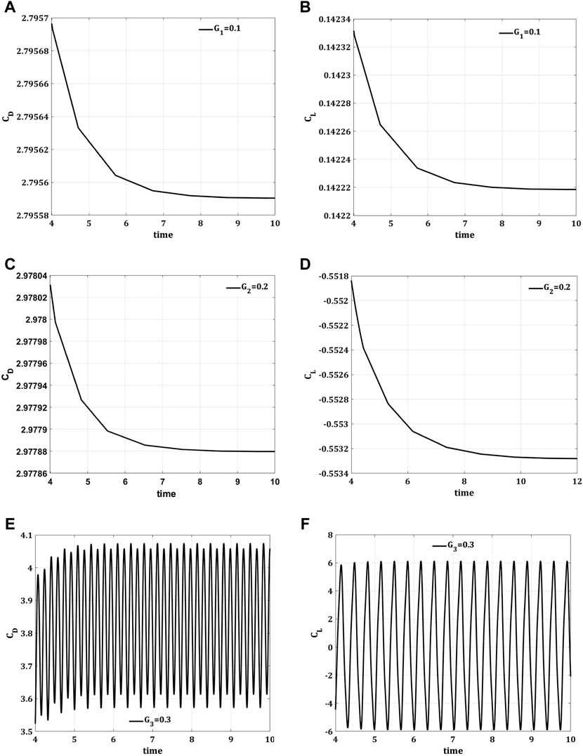
FIGURE 10. Impact of splitter plate with various gap separations (A,B) G1 = 0.1, (C,D) G2 = 0.2, (E,F) G3 = 0.3 on drag coefficient (CD) and lift coefficient (CL), w.r.t time
4.2 Effects of Power-Law Fluids
Figures 11A–F and Figures 12A–F are the velocity profiles for a laminar, incompressible, and transient flow of power-law fluid [41] in a channel with base Reynolds number
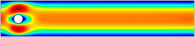
FIGURE 11. Velocity profile, at
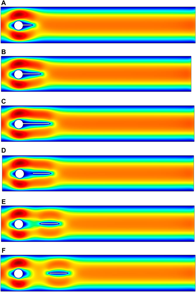
FIGURE 12. Influence of an attached splitter plate of length (A) L1 = 0.1, (B) L2 = 0.2, (C) L3 = 0.3 and gap separation (D) G1 = 0.1, (E) G2 = 0.2, (F) G3 = 0.3 on velocity, at
The pressure profiles are also presented in Figures 13A–F and Figures 14A–F. Figure 13 is showing the pressure profile in the absence of a passive device used in our present study for the control of hydrodynamic forces. The impact of the passive device, a splitter plate on the pressure profile for power-law fluid, is obvious in Figures 14A–C. The pressure is maximum at the stagnation point on the obstacle as shown in Figures 13A–F and Figures 14A–F. However, from Figures 14A–C, the effect of pressure can also be seen on the splitter plate in the downstream flow region for the case when the plate is at some gap separation from the obstacle.
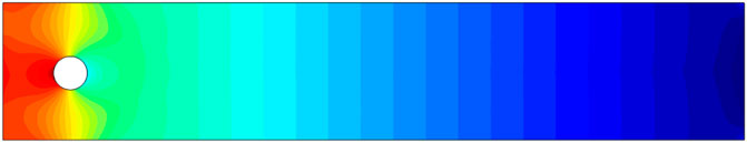
FIGURE 13. Pressure profile, at
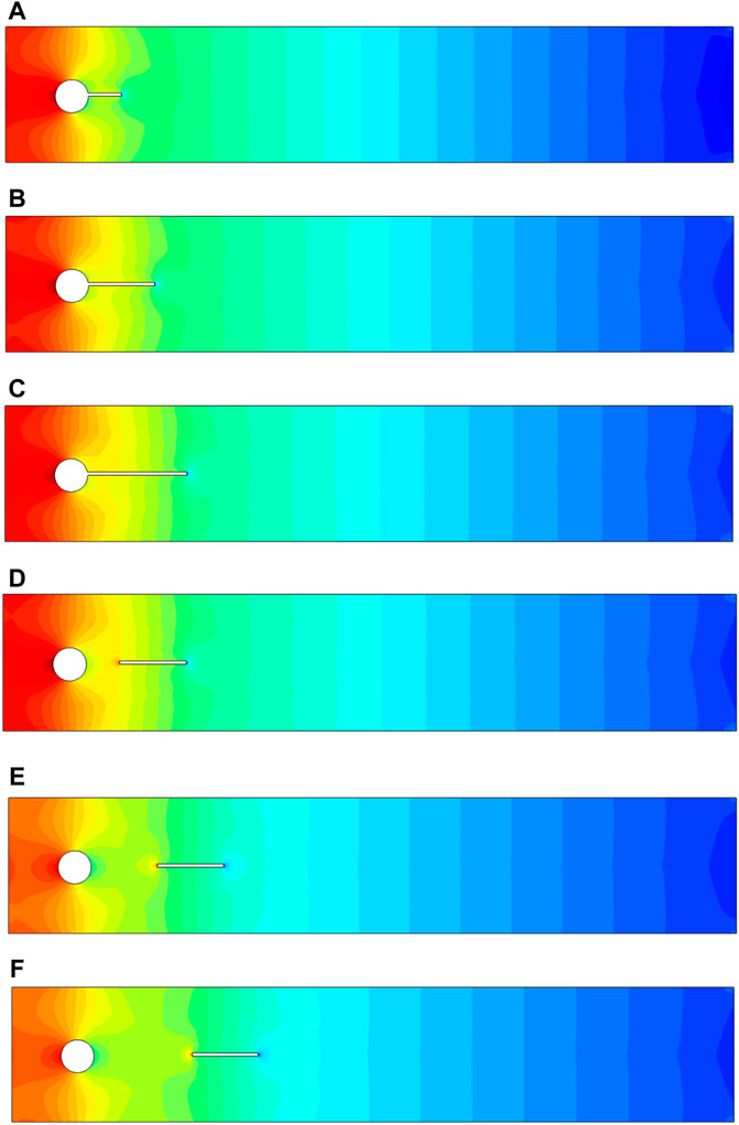
FIGURE 14. Influence of an attached splitter plate of length (A) L1 = 0.1, (B) L2 = 0.2, (C) L3 = 0.3 and gap separation (D) G1 = 0.1, (E) G2 = 0.2, (F) G3 = 0.3 on pressure, at
The main focus of the present study is the control of hydrodynamic forces, and in this section, the results are presented for non-Newtonian power-law fluid. The impact of a passive control device that is a splitter plate placed horizontally in the downstream flow region on the reduction of drag force is wonderful. Table 3 provides a comparison between the maximum and minimum values of drag and lift coefficients. The base Reynolds number during simulations is taken as
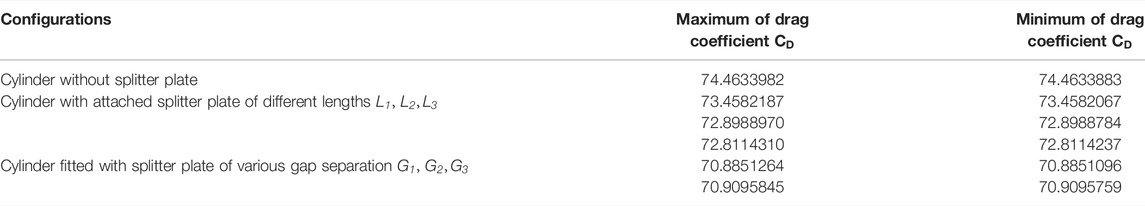
TABLE 3. Comparison between maximum and minimum values of drag and lift coefficients for various configurations.
For a laminar, transient flow of a nonlinear fluid [34], the difference between the maximum and minimum values of drag coefficient
Although the configuration shown in Figure 1 is good for suppressing the drag force on the obstacle in a channel, the adjustment of the splitter plate depicted in Figure 2 is evidenced by Table 3 as the more efficient strategy for control of drag force for power-law fluid. The gap separation of the splitter plate has a great influence on the minimization of the drag coefficient
5 Conclusion
The damages caused by the unsteady forces that occur because of the interaction with solid structures are very costly. For avoiding disastrous incidents, control devices (passive or active) are highly required. In the last few decades, because of the vast applications especially in engineering fields, the usage of both active and passive control devices admired a lot. Throughout this work, the control effect is investigated by using a passive device, i.e., a splitter plate. The current study is based on the usage of splitter plates in two different ways. The first technique used here is to attach a splitter plate of various lengths to the circular obstacle, and the second one is to fit a splitter plate of fixed length at various gap separations from the obstacle. Using the Navier–Stokes equation in two-dimensional and boundary constraints, the physical problem and corresponding rheological rules are mathematically expressed. A reliable computational tool, the finite element method, is required for the current investigation. The results are shown using graphical patterns. The velocity and pressure variations are represented graphically. The reduction in drag coefficient and variation in lift coefficient are also represented in the Newtonian case [33]. For nonlinear fluid, the impact on drag reduction is discussed using the power-law model [34]. The important findings are as follows:
• A comparison of drag and lift coefficient has been done with and without splitter plate not only for Newtonian fluid but also for non-Newtonian fluid using the power-law model.
• In the presence of a splitter plate, a reduction in drag coefficient has been observed.
• For a smaller length of the plate, the lift is periodic; however, with an increase in the length, it converges to a fixed value and loss its periodic behavior.
• An effective reduction of drag coefficient is noticed by attaching a splitter plate of length equal to two times
• For the smallest gap separation
• By comparing results for power-law fluids, it can be concluded that by fitting the splitter plate with gap separation from the obstacle, the drag coefficient reduces much more than by attaching the plate to the obstacle.
• It is concluded that utilizing an attached splitter plate of length
• In conclusion, a splitter plate can function to control fluid forces whether it is attached or detached, based on plate length and gap separation between obstacle and plate, respectively.
Data Availability Statement
The raw data supporting the conclusions of this article will be made available by the authors, without undue reservation.
Author Contributions
QA wrote the manuscript, RM supervised and performed the validation, QA and AM conducted modeling and simulation.
Funding
This research work was funded by institutional fund projects under no. (IFP-A-2022-2-5-24).
Conflict of Interest
The authors declare that the research was conducted in the absence of any commercial or financial relationships that could be construed as a potential conflict of interest.
Publisher’s Note
All claims expressed in this article are solely those of the authors and do not necessarily represent those of their affiliated organizations, or those of the publisher, the editors, and the reviewers. Any product that may be evaluated in this article, or claim that may be made by its manufacturer, is not guaranteed or endorsed by the publisher.
Acknowledgments
The authors gratefully acknowledge the technical and financial support from the Ministry of Education and the University of Hafr Al Batin, Saudi Arabia.
References
1. Triantafyllou GS, Triantafyllou MS, Chryssostomidis C. On the Formation of Vortex Streets Behind Stationary Cylinders. J Fluid Mech (1986) 170:461–77. doi:10.1017/s0022112086000976
2. Rashidi S, Hayatdavoodi M, Esfahani JA. Vortex Shedding Suppression and Wake Control: A Review. Ocean Eng (2016) 126:57–80. doi:10.1016/j.oceaneng.2016.08.031
3. Zdravkovich MM. Review and Classification of Various Aerodynamic and Hydrodynamic Means for Suppressing Vortex Shedding. J Wind Eng Ind Aerodynamics (1981) 7(2):145–89. doi:10.1016/0167-6105(81)90036-2
4. Roshko A. On the Drag and Shedding Frequency of Two-Dimensional bluff Bodies (1954). Washington: NACSA.
5. Roshko A. On the Wake and Drag of bluff Bodies. J Aeronaut Sci (1955) 22(2):124–32. doi:10.2514/8.3286
6. Bearman PW. Investigation of the Flow behind a Two-Dimensional Model with a blunt Trailing Edge and Fitted with Splitter Plates. J Fluid Mech (1965) 21(2):241–55. doi:10.1017/s0022112065000162
7. Gerrard JH. The Mechanics of the Formation Region of Vortices behind bluff Bodies. J Fluid Mech (1966) 25(2):401–13. doi:10.1017/s0022112066001721
8. Apelt CJ, West GS, Szewczyk AA. The Effects of Wake Splitter Plates on the Flow Past a Circular cylinder in the Range 104R4. J Fluid Mech (1973) 61(1):187–98. doi:10.1017/s0022112073000649
9. Apelt CJ, West GS. The Effects of Wake Splitter Plates on Bluff-Body Flow in the Range 104 < R < 5 × 10⁴. Part 2. J Fluid Mech (1975) 71(1):145–60. doi:10.1017/s0022112075002479
10. Unal MF, Rockwell D. On Vortex Formation from a Cylinder. Part 2. Control by Splitter-Plate Interference. J Fluid Mech (1988) 190:513–29. doi:10.1017/s0022112088001430
11. Hwang J-Y, Yang K-S, Sun S-H. Reduction of Flow-Induced Forces on a Circular cylinder Using a Detached Splitter Plate. Phys Fluids (2003) 15(8):2433–6. doi:10.1063/1.1583733
12. Ozono S. Vortex Suppression of the cylinder Wake by Deflectors. J Wind Eng Ind Aerodyn (2003) 91(1–2):91–9. doi:10.1016/s0167-6105(02)00337-9
13. Akilli H, Sahin B, Filiz Tumen N. Suppression of Vortex Shedding of Circular cylinder in Shallow Water by a Splitter Plate. Flow Meas Instrumentation (2005) 16(4):211–9. doi:10.1016/j.flowmeasinst.2005.04.004
14. Choi H, Jeon W-P, Kim J. Control of Flow Over a Bluff Body. Annu Rev Fluid Mech (2008) 40:113–39. doi:10.1146/annurev.fluid.39.050905.110149
15. Serson D, Meneghini JR, Carmo BS, Volpe EV, Assi GRS. Numerical Study of the Flow Around a Circular cylinder with Dual Parallel Splitter Plates. In: Instability and Control of Massively Separated Flows. Springer (2015). p. 169–74. doi:10.1007/978-3-319-06260-0_25
16. Cete AR, Unal MF. Effects of Splitter Plate on Wake Formation from a Circular cylinder: A Discrete Vortex Simulation. Comput Fluid Dyn (1992) 92:349–56.
17. Kwon K, Choi H. Control of Laminar Vortex Shedding behind a Circular cylinder Using Splitter Plates. Phys Fluids (1996) 8(2):479–86. doi:10.1063/1.868801
18. Chen W-L, Chen G-B, Xu F, Huang Y-w., Gao D-L, Li H. Suppression of Vortex-Induced Vibration of a Circular cylinder by a Passive-Jet Flow Control. J Wind Eng Ind Aerodynamics (2020) 199:104119. doi:10.1016/j.jweia.2020.104119
19. Gao D-L, Chen G-B, Huang Y-W, Chen W-L, Li H. Flow Characteristics of a Fixed Circular cylinder with an Upstream Splitter Plate: On the Plate-Length Sensitivity. Exp Therm Fluid Sci (2020) 117:110135. doi:10.1016/j.expthermflusci.2020.110135
20. Chen G, Chen W, Min X, Gao D. A Coupled Model for Vortex Induced Vibration of a Circular cylinder with and without Passive-Jet Flow Control. J Fluids Structures (2022) 110:103541. doi:10.1016/j.jfluidstructs.2022.103541
21. Akram S, Afzal F, Afzal Q. Impact of Nanofluids and Magnetic Field on the Peristaltic Transport of a Couple Stress Fluid in an Asymmetric Channel with Different Wave Forms. Therm Sci (2020) 24(2B):1407–22. doi:10.2298/tsci190720389a
22. Akram S, Zafar M, Hussain A, Rana MA. Effects of Inclined Magnetic Field on Peristaltic Flow of a Hyperbolic tangent Fluid Model with Double-Diffusive Convection in Nanofluids. Rev Tec La Fac Ing Univ Del Zulia (2016) 39:186–207. doi:10.21311/001.39.8.24
23. Akram S, Athar M, Saeed K, Umair MY. Double-diffusive Convection with Peristaltic Wave in Sisko Fluids along with Inclined Magnetic Field and Channel. Waves in Random and Complex Media (2021) 23 1–23. doi:10.1080/17455030.2021.1983238
24. Tanner RI, Walters K. Rheology: An Historical Perspective. Amsterdam, Netherland: Elsevier (1998).
25. Chhabra RP, Richardson JF. Non-Newtonian Flow and Applied Rheology: Engineering Applications. Amsterdam, Netherland: Butterworth-Heinemann (2011).
26. Dogonchi AS, Seyyedi SM, Hashemi-Tilehnoee M, Ganji DD. Investigation of Sedimentation Process of Soluble Spherical Particles in a Non-Newtonian Medium. J Colloid Interf Sci (2018) 530:532–7. doi:10.1016/j.jcis.2018.07.004
27. Seyyedi SM, Sahebi N, Dogonchi AS, Hashemi-Tilehnoee M. Numerical and Experimental Analysis of a Rectangular Single-phase Natural Circulation Loop with Asymmetric Heater Position. Int J Heat Mass Transfer (2019) 130:1343–57. doi:10.1016/j.ijheatmasstransfer.2018.11.030
28. Andersson HI, Bech KH, Dandapat BS. Magnetohydrodynamic Flow of a Power-Law Fluid over a Stretching Sheet. Int J Non-Linear Mech (1992) 27(6):929–36. doi:10.1016/0020-7462(92)90045-9
29. Hassanien IA, Abdullah AA, Gorla RSR. Flow and Heat Transfer in a Power-Law Fluid over a Nonisothermal Stretching Sheet. Math Computer Model (1998) 28(9):105–16. doi:10.1016/s0895-7177(98)00148-4
30. Abel MS, Datti PS, Mahesha N. Flow and Heat Transfer in a Power-Law Fluid over a Stretching Sheet with Variable thermal Conductivity and Non-uniform Heat Source. Int J Heat Mass Transf (2009) 52(11–12):2902–13. doi:10.1016/j.ijheatmasstransfer.2008.08.042
31. Mahmood R, Bilal S, Majeed AH, Khan I, Nisar KS. Assessment of Pseudo-plastic and Dilatant Materials Flow in Channel Driven Cavity: Application of Metallurgical Processes. J Mater Res Technology (2020) 9(3):3829–37. doi:10.1016/j.jmrt.2020.02.009
32. Mahmood R, Hussain Majeed A, Ain Qu., Awrejcewicz J, Siddique I, Shahzad H. Computational Analysis of Fluid Forces on an Obstacle in a Channel Driven Cavity: Viscoplastic Material Based Characteristics. Materials (2022) 15(2):529. doi:10.3390/ma15020529
33. Schäfer M, Turek S, Durst F, Krause E, Rannacher R. Benchmark Computations of Laminar Flow Around a cylinder. In: Flow Simulation with High-Performance Computers II. Springer (1996). p. 547–66.
Keywords: circular obstacle, splitter plate, fluid forces control, transient flow, finite element method
Citation: Ain QU, Khan Y, Mahmood R, Alameer A, Majeed AH and Faraz N (2022) Passive Control of Hydrodynamic Forces on a Circular Obstacle in a Transient Flow: FEM Computations. Front. Phys. 10:928087. doi: 10.3389/fphy.2022.928087
Received: 25 April 2022; Accepted: 20 June 2022;
Published: 09 August 2022.
Edited by:
Kh S Mekheimer, Al-Azhar University, EgyptReviewed by:
Shankar B M, PES University, IndiaSafia Akram, National University of Sciences and Technology (NUST), Pakistan
Copyright © 2022 Ain, Khan, Mahmood, Alameer, Majeed and Faraz. This is an open-access article distributed under the terms of the Creative Commons Attribution License (CC BY). The use, distribution or reproduction in other forums is permitted, provided the original author(s) and the copyright owner(s) are credited and that the original publication in this journal is cited, in accordance with accepted academic practice. No use, distribution or reproduction is permitted which does not comply with these terms.
*Correspondence: Y. Khan, eWFzaXJraGFuQHVoYi5lZHUuc2E=