 Song Gao
 Xudong Xie
95% of researchers rate our articles as excellent or good
Learn more about the work of our research integrity team to safeguard the quality of each article we publish.
Find out more
ORIGINAL RESEARCH article
Front. Phys. , 17 June 2022
Sec. Optics and Photonics
Volume 10 - 2022 | https://doi.org/10.3389/fphy.2022.923402
This article is part of the Research Topic Future Directions in Novel Laser Source Development: Dynamical Properties, and Beam Manipulation View all 14 articles
In this study, the designing method of multi-beam regenerative amplifiers with the repetitive rate was proposed and demonstrated. To obtain multi-beam regenerative amplifiers with uniform performance, the disparities in output energy, energy stability, and mode size were analyzed, and the detailed optimizing method was presented. With the designs, eight-beam regenerative amplifiers were developed. The output performances of eight-beam regenerative amplifiers were uniform. The output energies were in the range of 25.4–28.8 mJ, and the energy stabilities over two hours were in the range of 2.4%–5.1% (PV) and 0.3%–0.9% (RMS).
Neodymium glass (Nd:glass) is the best gain medium so far for inertial confinement fusion (ICF) lasers, such as the SG-series in China, the National Ignition Facility (NIF) in American, and the Megajoule in France [1–4]. The Nd:glass has good optical homogeneity, broad gain bandwidth (more than 20 nm), and the potential for large size and high doping concentration [5–7]. However, as the stimulated emission cross (σ) is small, the single-pass small-signal gain coefficient is small (g = nσ) at the same stored energy. Thus, in order to achieve sufficient total gain, multi-pass amplifiers are strongly preferable. Among them, the regenerative amplifier is a good candidate. First, the amplification pass can be several tens or more, and the total gain is very large (>109). Second, gain saturation induced by multi-pass amplification is particularly beneficial to improve the extraction efficiency and pulse-to-pulse energy stability [8–10]. Third, owing to the mode self-reproducing of the regenerative cavity, the beam quality is excellent, typically the fundamental mode. Therefore, the regenerative amplifier is commonly served as a high-gain compact module in the preamplifier of ICF lasers [11].
To date, numerous researches on the regenerative amplifier design have been conducted. In 1983, Magni et al. theoretically derived the general properties of resonators containing a variable lens and investigated the mode spot sizes, the dynamical stability, and the misalignment sensitivity [12]. This method was widely used in the regenerative amplifier design [13, 14]. Afterward, to overcome high misalignment sensitivity of the amplifier, a method was proposed for analyzing the impact of cavity misalignment on the mode drift of the gain media [15]. With these aforementioned methods, the regenerative amplifier can be designed and developed. However, in the situation that multi-beam lasers are required to simultaneously irradiate onto the target (e.g., ICF), in order to obtain the best laser–matter interaction results, the performances of multi-beam are desired to be uniform, including output energy and temporal waveform. This is generally called energy/power balance across multi-beam lasers [16–19]. Therefore, as a part of ICF lasers, the uniformities of multi-beam regenerative amplifiers are strongly desired. Since the laser is amplified many times in the regenerative amplifier, slight parameter differences of optical components or weak focal lensing can contribute to large changes in mode radius and energy, i.e., disparities across multi-beam lasers. This will influence the power balance of ICF lasers.
In this study, the designing method of multi-beam regenerative amplifiers with the repetitive rate was proposed and demonstrated. The disparities in output energy, energy stability, and mode size were analyzed with the practical optical component parameters and operating conditions. The detailed designing and optimizing method was presented to obtain a multi-beam regenerative amplifier with uniform performance. With the designs, eight-beam regenerative amplifiers were developed. The output performances were measured. The output performances of eight-beam regenerative amplifiers were uniform. The output energies were in the range of 25.4–28.8 mJ, and the energy stabilities over two hours were in the range of 2.4%–5.1% (PV) and 0.3%–0.9% (RMS). The results were in good accordance with the design results.
The simplified regenerative amplifier concept is shown in Figure 1. The amplifier contains two cavity mirrors (CM1 and CM2), a laser head (LH), a Pockels cell (PC), a quarter-wave plate (QWP), a thin-film polarizer (P), and a lens (L). The L, CM1, and CM2 are used to determine the mode size. The PC and QWP are used to control the amplification pass. The cavity length is 6750mm, which corresponds to 45 ns round trip. Thus, a laser pulse with a maximum of 25 ns temporal width can be amplified, considering the 10 ns rising edge of the PC.
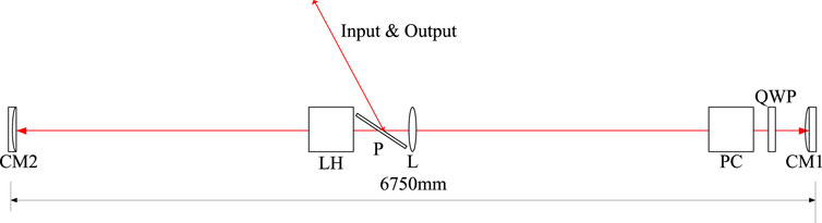
FIGURE 1. Simplified regenerative amplifier concept. CM1 and CM2: cavity mirrors; LH: laser head; P: thin-film polarizer; L: lens; PC: Pockels cell; QWP: quarter-wave plate.
The input laser with s-polarization is injected into the amplifier cavity from P. When the input laser first passes through the PC, the PC is powered off. After a round trip, the laser turns to be p-polarization with the help of QWP. After the laser passes through the PC for the second time, the PC is powered with a quarter-wave voltage, and the function of the PC and QWP is similar to that of a half-wave plate. The laser polarization state keeps constant during a round trip, and the laser can be amplified successively until the PC is powered off. The output laser with s-polarization is outputted from P. The total amplification pass is fix(t×c/l), where t is the voltage width of PC, c is the speed of light, l is the cavity length, and the function fix(x) is obtaining the maximum integer of x.
In practical multi-beam regenerative amplifiers, due to the parameter differences of optical components (e.g., reflectivity and transmission), the total loss of the cavity is different. Moreover, in laser–matter interactions with multi-beam lasers, the moments of multi-beam lasers arriving at the target must be the same. Thus, the amplification pass (or the voltage width of PC) should be identical. In this circumstance, the output energy and energy stability exhibit obvious differences from beam to beam. Here, the typical parameters of optical components are shown in Table1. In this table, four configurations of parameters are included. The design baseline is the typical parameter of the optical component. The minimum value, maximum value, and mean value are obtained by actually measuring the minimum, maximum, and mean parameters from over 100 real components.
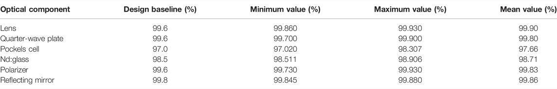
TABLE 1. Typical parameters of optical components.
With these parameters in Table1, the energy curves of different configurations are calculated theoretically. In the theoretical calculations, the Avizonis–Grotbeck model is adopted [20]. Compared with the commonly used Frantz–Nodvik model [21], the Avizonis–Grotbeck model involves the loss of gain medium, which is important, especially for rod-shaped gain medium and multi-pass amplification, which makes the theoretical simulations more exact. Here, the static loss and dynamic loss of Nd:glass are 0.12% cm−1 and 0.36% cm−1, respectively, which are obtained from the Nd:glass factory. The static loss and dynamic loss are the loss without and with LD pumping, respectively. Combined with the input energy of ∼0.1 μJ, the theoretical energy curves are calculated, as shown in Figure 2. In the figure, the small-signal gain and the amplification pass are chosen to be 1.269 and 96-pass, respectively, so as to satisfy the output energy of 25 mJ and excellent energy stability at design baseline (black line in Figure 2). Due to the different losses, the energy and energy stability of the four configurations show undesirable disparities. For configurations of the minimum value, mean value, and maximum value, the output energy is far larger than 25 mJ before the laser is exported from the regenerative amplifier. The optical damages are probably induced and affect the safe operations. Moreover, the performances of energy stability are also different. For design baseline, the curve at 0.1 μJ is nearly flat. It means that the output energy is extremely insensitive to the fluctuations of input energy. However, for the minimum value, mean value, and maximum value, the output energy varies with the fluctuations of input energy, which will influence the power balance of multi-beam lasers.
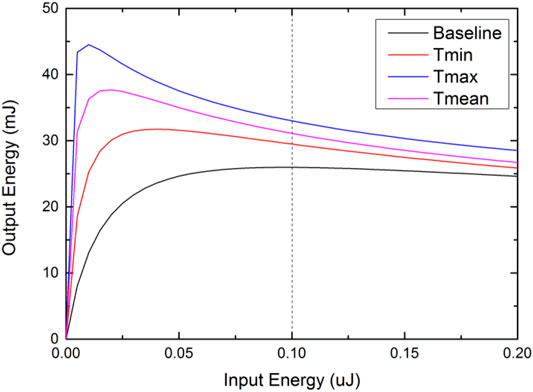
FIGURE 2. Energy curves of different configurations.
In order to obtain uniform energy stabilities of multi-beam lasers and avoid optical damage, an active method of controlling the product of gain and loss is adopted. Here, by slightly adjusting the small-signal gain, the products of gain and loss of multi-beam regenerative amplifiers are uniform. With this method, the optimized small-signal gain of four configurations are 1.269, 1.254, 1.233, and 1.242, respectively. The optimized energy curves of four configurations are shown in Figure 3. From the figure, the output energies of four configurations are all in the safe operating range of 25–35 mJ. The energy stabilities are nearly uniform and not sensitive to the fluctuations of the input laser.
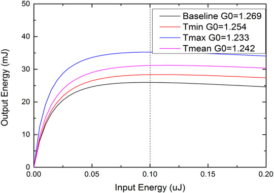
FIGURE 3. Optimized energy curves of four configurations.
The laser head is a diode-side-pumped circular Nd:glass rod with a 1 Hz repetition rate. The profile is shown in Figure 4. The laser head consists of Nd:glass, cooling fluid, quartz tube, and pump ring module. The geometric size of the rod is Ф5 mm × 100 mm. The gain medium is N31 Nd:glass whose Nd3+ concentration is 2.2 wt% [22, 23]. The ends of the rod are tapered to stifle unwanted whispering gallery parasitic modes. The quartz tube is 1 mm thickness, which is used to separate the cooling fluid from the diode. The pumping ring module is a 5-side ring-pumping scheme with a pumping power of 2.5 kW, and two pumping ring modules are incorporated. The center wavelength of the diode is 802 nm.
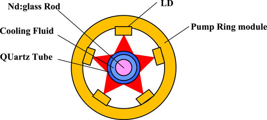
FIGURE 4. Profile of the laser amplifier.
In order to obtain excellent beam quality, the pumping is required to be uniform[24]. The simulated pumping uniformity with the aforementioned parameters is shown in Figure 5 using the ray-tracing method. The uniformity in the center 3 mm × 3 mm region is 91.8%.
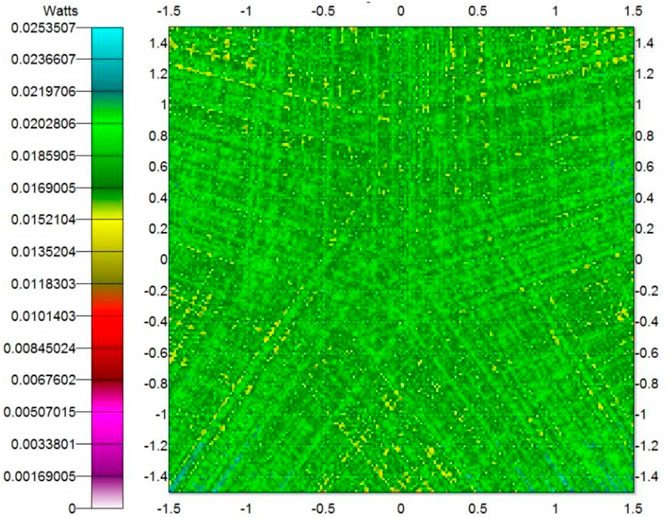
FIGURE 5. Pumping distribution of LH.
The small-signal gain is estimated according to the energy-transfer mechanism [25], including the pumping transfer efficiency, absorbing efficiency, quantum efficiency, Stokes efficiency, and storage efficiency. In this case, the total energy transfer efficiency (ηtot) is 26%. The maximum small-signal gain is estimated to be 1.95 using Eq. 1. It is slightly larger than the aforementioned required small-signal gain.
where Pp is the pumping power; tp is the pumping width, which is 500 μs; Es is saturated fluence (4.97 J/cm2 for N31 Nd:glass); and A is the section area of the gain medium.
Due to the long cavity length, even weak focal lensing can contribute to large changes in mode radius for non-optimized cavity configurations, i.e., undesired disparities across multi-beam lasers. For multi-beam regenerative amplifiers, on the one hand, as mentioned previously, in order to obtain uniform output energy and energy stability, the small-signal gain of each beam is strongly dependent on the optical loss. This means the pumping power and induced thermal lensing are different. According to the laser head design and thermal analyses, at the small-signal gain of 1.269 (design baseline in Section 2.2), the corresponding thermal lensing is about 25 m. Furthermore, one can easily estimate the thermal lensing for the other three cavity loss configurations, which are 23.75 m (minimum value), 22.74 m (mean value), and 21.98 m (maximum value), respectively. On the other hand, the diode pumping fluctuations induced by power supply and the machining errors of optical components such as CM1, CM2, and L will also cause mode radius changing. Thus, the cavity should be stable over a large range of the thermal lens.
The cavity design is developed by utilizing an analytic ABCD description [20]. By varying the end mirror and cavity lens radius and the distance of optical components in Figure 1, the stability zones for each cavity parameter were evaluated. Only the cavity parameters meeting the following constraints were analyzed: first, the mode radius in the rod is ∼1.5 mm, so as to obtain large energy without damage risk. Second, the cavity should be stable with the thermal lensing changing from 21.98 to 25 m or more. This is necessary when changing the small-signal gain for multi-beam lasers. Third, the mode radius on the other optical components is larger than 0.5 mm to avoid optical damages. With these criteria, the optimized cavity parameters are as follows: the radii of the curvature of CM1 and CM2 are −10,000 and 10,000 mm, respectively. The focal length of L is 2,430 mm, and its position is at the center of the cavity. The distance between LH and CM2 is 2,750 mm. The corresponding stability zones are shown in Figure 6. In the figure, the x-axis is the thermal focal power, which is reciprocal to thermal lensing, and the y-axis is the mode radius. From the figure, at the thermal focal power of 4 × 10⁻⁵ mm−1 (i.e., 25 m for thermal lensing), the cavity mode size is insensitive to the thermal lensing variations. When the thermal focal power varies by ±20%, the mode radius at Nd:glass changes to smaller than 0.1%. Considering all the factors that may result in mode size changes including the diode pumping fluctuation, the thermal lensing variations, and machining errors of optical components, the total mode radius changes are small. This is negligible. With the parameters, the mode size of the regenerative cavity is calculated, as shown in Figure 7. The mode radii in the laser head (LH), lens (L), and cavity mirrors (CM1 and CM2) are 1.5, 1.75, 0.98, and 0.65 mm, respectively.
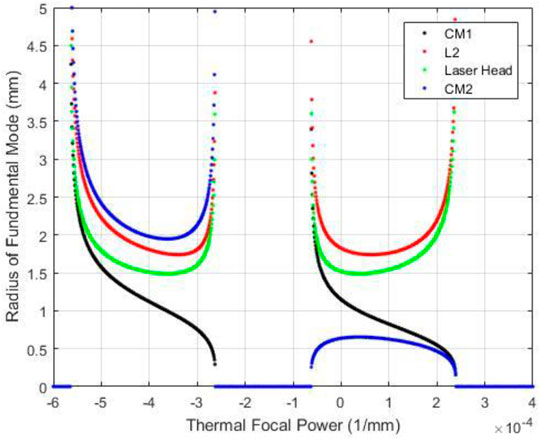
FIGURE 6. Optimized stability zones of the regenerative cavity.
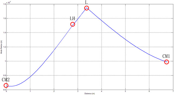
FIGURE 7. Mode size of the regenerative cavity.
Based on the regenerative amplifier design, eight-beam regenerative amplifiers were developed, named L1–L4 and R1–R4. The eight beams were installed on a 4 × 2 truss. The L1–L4 and R1–R4 were image-mirrored. The schematic diagram of the regenerative amplifier is shown in Figure 8.
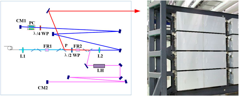
FIGURE 8. Schematic diagram of the regenerative amplifier.
The amplification pass is 112-pass, which is larger than the designed 96-pass. It is mainly due to the imperfect mode matching between the input laser mode and cavity mode. At 112-pass amplification, the output energy and energy stability of eight-beam regenerative amplifiers are shown in Table 2. The output energies are in the range of 25.4–28.8 mJ, and the energy stabilities over two hours are 2.4%–5.1% (PV) and 0.3%–0.9% (RMS). This is in good accordance with the designed results. The corresponding energy stability curves are shown in Figure 9. From the figure, some slow variations can be seen, which mainly come from the slight misalignment induced by temperature changes of environment and energy fluctuations of the input laser.
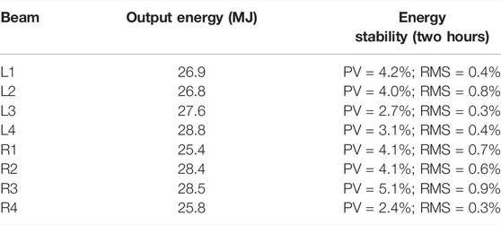
TABLE 2. Output energy and energy stability of eight-beam regenerative amplifiers.
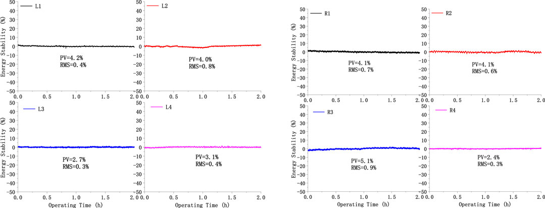
FIGURE 9. Energy stabilities of eight-beam regenerative amplifiers over two hours.
The output beam is measured by CCD positioned after the polarizer P. The distance between the CCD and the lens L2 is identical to the distance between the laser head LH and the lens L2. Hence, the measured beam size is equivalent to that on LH. The typical beam is shown in Figure 10. The beam quality of eight beam lasers is good and uniform, exhibiting Gauss distribution. The beam size at 1/e2 is about 3 mm, which is in good accordance with the designed value.
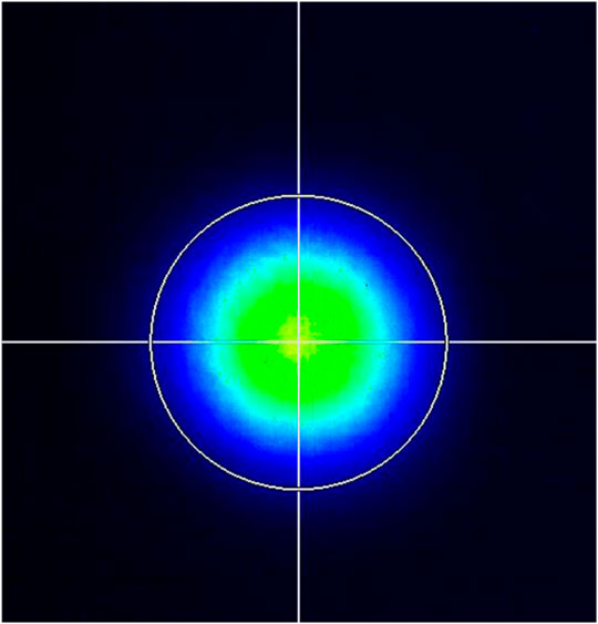
FIGURE 10. Typical beam of the regenerative amplifier.
In this study, the designing method of multi-beam regenerative amplifiers with the repetitive rate was proposed and demonstrated. To obtain multi-beam regenerative amplifiers with uniform performance, the disparities in output energy, energy stability, and mode size were analyzed, and the detailed optimizing method was presented. With the designs, eight-beam regenerative amplifiers were developed. The output performances are measured including the output energy and energy stability. The output performances of eight-beam regenerative amplifiers are uniform. The output energies are in the range of 25.4–28.8 mJ, and the energy stabilities over two hours are in the range of 2.4%–5.1% (PV) and 0.3%–0.9% (RMS). The results are in good accordance with the design results.
The original contributions presented in the study are included in the article/supplementary material; further inquiries can be directed to the corresponding author.
SG: regenerative amplifier design, demonstration, and manuscript writing. JT: regenerative amplifier demonstration. CF: regenerative amplifier test. KY: regenerative amplifier design.
The authors declare that the research was conducted in the absence of any commercial or financial relationships that could be construed as a potential conflict of interest.
All claims expressed in this article are solely those of the authors and do not necessarily represent those of their affiliated organizations, or those of the publisher, the editors, and the reviewers. Any product that may be evaluated in this article, or claim that may be made by its manufacturer, is not guaranteed or endorsed by the publisher.
1. Miller GH, Moses EI, Wuest CR. The National Ignition Facility. Opt Eng (2004) 43(12):2841–53. doi:10.1117/1.1814767
2. André ML. Status of the LMJ Project. In: Solid State Lasers for Application to Inertial Confinement Fusion: Second Annual International Conference; 8 December 1997; Paris, France. Proceeding of SPIE (1997). p. 38–42.
3. Zheng WG, Zhang XM, Wei XF, Jing F, Sui Z, Zheng K, et al. Status of the SG-III Solid-State Laser Facility. J Phys Conf Ser (2008) 112:032009. doi:10.1088/1742-6596/112/3/032009
4. Fan W, Jiang YE, Wang JF, Wang X, Huang D, Lu X, et al. Progress of the Injection Laser System of SG-II. High Power Laser Sci Eng (2018) 6:e34. doi:10.1017/hpl.2018.31
5. Hogan WJ, Moses EI, Warner BE, Sorem MS, Soures JM. The National Ignition Facility. Nucl Fusion (2000) 41:567–73.
6. Boehly TR, Brown DL, Craxton RS, Keck RL, Knauer JP, Kelly JH, et al. Initial Performance Results of the OMEGA Laser System. Opt Commun (1997) 133:495–506. doi:10.1016/s0030-4018(96)00325-2
7. Campbell JH, Suratwala TI. Nd-doped Phosphate Glasses for High-Energy/high-Peak-Power Lasers. J Non-Crystalline Sol (2000) 263-264:318–41. doi:10.1016/s0022-3093(99)00645-6
8. Yao K, Gao S, Tang J, Xie X, Fan C, Lu Z, et al. Off-axis Eight-Pass Neodymium Glass Laser Amplifier with High Efficiency and Excellent Energy Stability. Appl Opt (2018) 57:8727–32. doi:10.1364/ao.57.008727
9. Yao K, Xie X, Tang J, Fan C, Gao S, Lu Z, et al. Diode-side-pumped Joule-Level Square-Rod Nd:glass Amplifier with 1 Hz Repetition Rate and Ultrahigh Gain. Opt Express (2019) 27(23):32912–23. doi:10.1364/oe.27.032912
10. Yao Z, Cheng L, Tang R, Xue J. Wakefield Generation by Chirped Super-gaussian Laser Pulse in Inhomogeneous Plasma. Plasma Sci Technol (2018) 20:115002. doi:10.1088/2058-6272/aacbbf
11. Spaeth ML, Manes KR, Kalantar DH, Heebner JE, Bliss ES, Miller PE, et al. Description of the NIF Laser. Fusion Sci Technolegy (2016) 26(1):25–145. doi:10.13182/FST15-144
12. Magni V. Multielement Stable Resonators Containing a Variable Lens. J Opt Soc Am A (1987) 4(10):1962–9. doi:10.1364/josaa.4.001962
13. Bowers M, Burkhart S, Cohen S, Erbert G, Heebner J, Herman M, et al. The Injection Laser System on the National Ignition Facility. In: Solid State Lasers XVI: Technology and Devices; 9 March 2007; San Jose, California, United States. International Society for Optics and Photonics (2007). p. 64511M.
14. Huang W, Wang J, Lu X, Fan W, Li X, Zhu J. Design and Demonstration of a Passive-Cooled, Innoslab-Based Nd:glass Regenerative Amplifier with High Beam Quality. OSA Continuum (2019) 2(6):1838–43. doi:10.1364/osac.2.001838
15. Shi Y, Zhang P, Jiang Y, Wang J, Zhou L, Lu X, et al. High-stability, High-Energy Nd:glass Rod Regenerative Amplifier with Compensation for Cavity Misalignment. Appl Opt (2021) 60(5):1150–8. doi:10.1364/ao.414923
16. Sampat S, Kosc TZ, Bauer KA, Dean RD, Donaldson WR, Kwiatkowski J, et al. Power Balancing the Multibeam OMEGA Laser. Appl Opt (2018) 57(32):9571–82. doi:10.1364/ao.57.009571
17. Jones OS, Speck DR, Haan SW. The NIF Power Balance. In: 3rd International Conference on Solid-state Lasers for Applications to Inertial Confinement Fusion; Jun 1998; Monterey, CA, USA. Proceeding of SPIE (1999). p. 78–104.
18. Kalantar DH, Dixit SN, Haynam CA, Mehta NC, Shaw MJ, Widmayer CC, et al. NIF Power Balance Performance Modeling and Testing. In: Proceeding of the 49th Annual Meeting of the Division of Plasma Physics; November 12-16, 2007; Orlando,florida. American physicl society (2007). p. 52.
19. Garrec BJL, Nicolas O. Laser Performance Operation Model and its Application to LIL Energy and Power Balance. J Phys Conf Ser (2008) 112:032019. doi:10.1088/1742-6596/112/3/032019
20. Avizonis PV, Grotbeck RL. Experimental and Theoretical Ruby Laser Amplifier Dynamics. J Appl Phys (1966) 37:687–93. doi:10.1063/1.1708238
21. Frantz LM, Nodvik JS. Theory of Pulse Propagation in a Laser Amplifier. J Appl Phys (1963) 34:2346–9. doi:10.1063/1.1702744
22. Hu L, Chen S, Tang J, Wang B, Meng T, Chen W, et al. Large Aperture N31 Neodymium Phosphate Laser Glass for Use in a High Power Laser Facility. High Power Laser Sci Eng (2014) 2:1–6. doi:10.1017/hpl.2014.4
23. Hu L, He D, Chen H, Wang X, Meng T, Wen L, et al. Research and Development of Neodymium Phosphate Laser Glass for High Power Laser Application. Opt Mater (2017) 63:213–20. doi:10.1016/j.optmat.2016.11.052
24. Clarkson WA. Thermal Effects and Their Mitigation in End-Pumped Solid-State Lasers. J Phys D: Appl Phys (2001) 34:2381–95. doi:10.1088/0022-3727/34/16/302
Keywords: regenerative amplifier, Nd:glass, laser beam characterization, multi-beam uniformity, diode-pumped
Citation: Gao S, Xie X, Tang J, Fan C, Fu X, Chen Z and Yao K (2022) Multi-Beam Large Fundamental Mode Neodymium Glass Regenerative Amplifier With Uniform Performance. Front. Phys. 10:923402. doi: 10.3389/fphy.2022.923402
Received: 19 April 2022; Accepted: 06 May 2022;
Published: 17 June 2022.
Edited by:
Xing Fu, Tsinghua University, ChinaReviewed by:
JiSi Qiu, Aerospace Information Research Institute (CAS), ChinaCopyright © 2022 Gao, Xie, Tang, Fan, Fu, Chen and Yao. This is an open-access article distributed under the terms of the Creative Commons Attribution License (CC BY). The use, distribution or reproduction in other forums is permitted, provided the original author(s) and the copyright owner(s) are credited and that the original publication in this journal is cited, in accordance with accepted academic practice. No use, distribution or reproduction is permitted which does not comply with these terms.
*Correspondence: Ke Yao, eXloMTQzQDE2My5jb20=
Disclaimer: All claims expressed in this article are solely those of the authors and do not necessarily represent those of their affiliated organizations, or those of the publisher, the editors and the reviewers. Any product that may be evaluated in this article or claim that may be made by its manufacturer is not guaranteed or endorsed by the publisher.
Research integrity at Frontiers
Learn more about the work of our research integrity team to safeguard the quality of each article we publish.