- College of Advanced Interdisciplinary Studies, National University of Defense Technology, Changsha, China
Fiber lasers have been widely used in medical care, industries, and scientific research in recent years. The coherent beam combining of fiber lasers with an internal phase control has drawn many interests at present, which is a promising method to achieve a large-scale optical phased array. In this article, we presented a cascaded internal phase control method to expand the internal all-fiber phased array. The method distributes the phase measurements to a series of internal Mach–Zender interferometers. Then, the phase of each loop is locked by the gradient descent algorithm. The electric control method to compensate π-ambiguity between channels is proposed. Finally, the phases of the three fiber beams are locked experimentally to verify the feasibility of the method, and the residue phase error is better than λ/22.
Introduction
Coherent beam combining (CBC) of the fiber laser array provides a promising way to obtain a higher output power than the monolithic fiber laser whose output power is limited by nonlinear effects and mode instability [1–3]. By aligning the phases of a bundle of fiber lasers, the far-field pattern presents a main lobe and several weak side lobes which will increase energy concentration and maintain the beam quality [4]. A large size optical phased array (OPA) of the fiber laser may provide a light source for laser-driven facilities such as a rapid transit to the Mars mission [5], the Breakthrough Starshot project [6–8], and the international coherent amplification network [9]. To realize the CBC of fiber lasers, phase control is one of the core works. The main task of the phase control is to compensate the phase noise in the laser chain [10]. There are many phase control methods such as interference measurement [11], dithering technique [12–15], artificial intelligence algorithm [16–19], and stochastic parallel gradient descent algorithm (SPGD) [20–23]. As a feedback control system, the phase control module of CBC should include a feedback loop. In general, a feedback loop is set outside the CBC system in free space. The light is transmitted by several mirrors or lens and then collected by using a photodetector (PD) or camera. Dozens of fiber lasers have been coherently combined based on this external structure and phase control methods mentioned previously [24–26].
To enlarge the fiber laser array, another feedback concept draws increasing attention which could be named as an internal feedback, correspondingly [27, 28]. A little part of light can be reflected when the laser emits to free space. The reflected light can be utilized as a feedback signal to achieve phase control by a proper structure design. According to the reflection principle, the structure can be divided into two categories: spatial [29, 30] and fiber-based [31]. The spatial reflection uses mirrors to reflect a small portion of the light back. Then, the PD gathers the back-reflected signal to close the loop. The fiber-based reflection is on the basis of Fresnel reflection at the air–glass interface. The back-reflected light travels inside the fiber and then is collected at the proper position by PD.
As far as the all-fiber-based internal phase control, some structures and phase-locking methods have been proposed such as the digitally enhanced heterodyne interferometry (DEHI) technique [32] and SPGD algorithm [33]. The structure of the all-fiber-based internal phase control usually contains a fiber coupler to divide the phase-locking task into forward phase-locking and backward phase-locking so that the internal backward light can be collected without turning back to the amplifier. In previous works, there is usually a common port in the backward loop such as the digitally enhanced heterodyne interferometry (DEHI) technique, and our previous work used the SPGD algorithm. The common port has its advantage of saving hardware resources and the disadvantage of introducing crosstalk. Another issue is that the backward lights have a round trip in the fibers, so the π-ambiguity is not discernible. In this article, we proposed a cascaded internal phase control of the all-fiber structure to remove the common port. The structure can improve the size-scaling ability for internal phase-locking. An electric control method to compensate π-ambiguity between channels is also proposed in this work. The π-ambiguity could be discernible in some degree with this cascaded structure, which will improve the practicality of the fiber laser array with internal phase control. By distributing the phases of measuring loops further through cascaded 3-dB couplers, the system can be broken up into a series of Mach–Zehnder interferometers. Phase locking can be achieved by locking the phases of two Mach–Zehnder interferometers of each channel, which is hopefully to improve control bandwidth while increasing the size of fiber laser array further.
Principle of the Cascaded Internal Phase Control
Schematic Representation of Cascaded Internal Phase-Locking
The schematic representation of cascaded internal phase-locking is shown in Figure 1. The system includes two parts: the main laser chain and a cascaded measuring loop. The seed laser is split into two channels by a 1 × 2 splitter. The first channel is pre-amplified and then split into N channels. Each channel passes through a phase modulator (PM), amplifier (AMP), and fiber coupler (99.9:0.1) in turns. Most laser outputs from the fiber coupler (99.9:0.1) to the collimator and emits to free space. The optical path mentioned previously can be called as the main laser chain. The second part inputs into a circulator and then inputs into a 3-dB fiber coupler, which can be named as the measuring loop. The laser is split into two beams. One of the two beams passes through a PM and then inputs into the fiber coupler (99.9:0.1). The light in the fiber coupler interferes with the remaining light of the first part. The PD gathers the interference signal and converts it into an electric signal. The phase controller receives the interference signal and controls the PM of the main laser chain to make the phase of the main laser chain consist within the corresponding measuring loop:
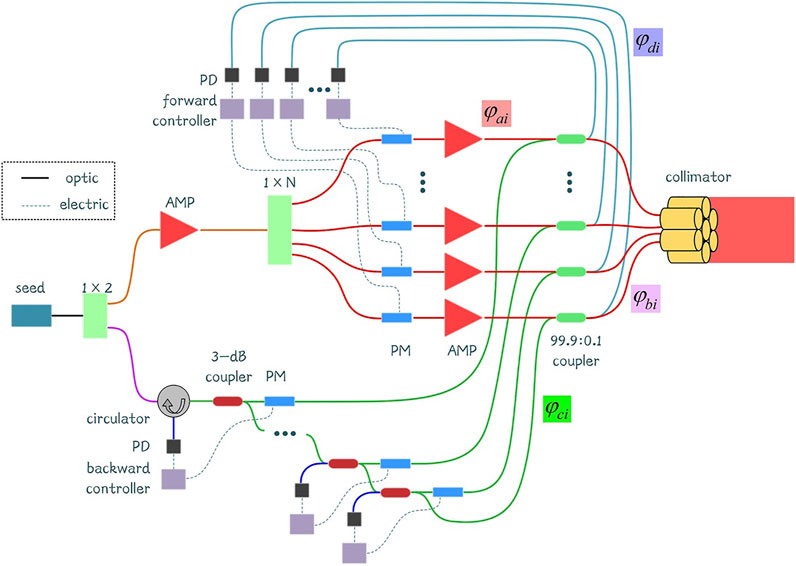
FIGURE 1. Schematic representation of a cascaded internal phase-locking. AMP, amplifier; PD, photodetector; PM, phase modulator.
Then, another output of the 3-dB fiber coupler inputs into a second 3-dB fiber coupler. This should be continued until the second part of the seed is split into N channels. The measuring loops are cascaded by this method. There are totally N-1 3-dB fiber couplers in the measuring loop. The laser from the main laser chain is reflected at the collimator with ∼4% reflectivity. The backward reflected light then goes back to the fiber coupler, PM of the measuring loop, and output from the 3-dB fiber coupler. The ith backward reflected light is interfered with the (i-1)th reflected backward light, where i = 2, 3, …, N. Then, the interference signal outputs from the (i-1)th 3-dB fiber coupler and is collected by the PD and phase controller. The phase-locking is achieved between channels by controlling the (i-1)th PM of the measuring loop as
Mach–Zehnder Interferometer and Phase Control Strategy
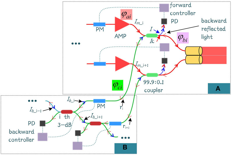
The schematic diagram of the Mach–Zehnder interferometer is shown in Figure 2. The ith loop is taken as an example. The input of Ib_i-1 (in blue) in the measure loop is split into two beams (Ib_i and Ib_i+1) with equal intensities shown in Figure 2B. The Ib_i is interfered with a part of the main laser Im_i (in red) at the fiber coupler (99.9:0.1), as shown in Figure 2A. The controller makes the signal of the forward PD in the Figure 2A maximized. According to the condition of the two-beam interference,
where Ic is the complementary output of another arm of the coupler, and θ = φai–φci is the phase difference of the two input arms. When Ib_i = Im_i = I0, the light intensity at forward PD is 4I0, and the light intensity to another arm is 0, which is benefitted to stabilize the output by reducing stray light. At the same time, θ = 0 and the phases of the two input arms are equal as Eq. 1.
The backward reflected light ri (red-dotted arrow) of the main laser goes back to the 3-dB fiber coupler, as shown in Figure 2B. The ith backward reflected light is interfered with (i+1)th backward reflected light ri+1 at the ith 3-dB fiber. The controller makes the signal of the backward PD in the Figure 2B minimized. Thus, almost all the light can go back to the input arm (the complementary arm of PD) of the 3-dB coupler to the previous stage. The phases of the two backward reflected lights are equal under this condition, as shown in Eq. 2. The interference light can continue to the (i-1)th 3-dB fiber coupler to form another Mach–Zehnder interferometer. This is repeated until all the backward light output from the circulator.
At last, all the backward reflected lights are gathered by PD after the circulator. The controller makes the signal maximum to let
The phase of each channel is locked.
Gradient Descent Algorithm
The main objective of each controller is to control the phase between the two beams. The gradient descent (GD) algorithm is utilized in this work. Different with the SPGD, the SPGD algorithm is used to control the multi-phase simultaneously, and GD can be used to solve the optimization problem of one object. The process of GD is as follows:
1) The initial phase φ0 is given;
2) The current value of evaluation function J0 is obtained;
3) A small step ∆φ is moved;
4) The current value of evaluation function J1 is obtained;
5) The phase φ1 = φ0 -γη(J1 - J0) is updated, where γ is the gain, and η is the direction; η = 1 means the optimized direction is minimum, and η = -1 means the optimized direction is maximum;
6) Steps (2)–(5) should be repeated.
The GD algorithm is executed by an advanced RISC machine (ARM) microcontroller with a max clock rate of 480 MHz.
Electric Control Method to Compensate π-ambiguity
As for the common factor 2 in Eq. 4, there may be π phase difference after collimators between the different beams. The reason for this is that the light for phase control does the round trip in the fibers [33]. The phase between the two adjacent beams after the collimators will be
where k is an integer. When k in the Eq. 6 is an odd number, the two beams will represent an interference of π phase difference in the far-field, as shown in Figure 3A. When k in Eq. 6 is an even number, the two beams will interfere with each other without a phase difference, as shown in Figure 3B. Due to the unknown initial phase and noise states, the odevity of k is uncertain. As for the phase control algorithm, no matter what k is, the feedback signal of the PD is the same. Hence, the π-ambiguity occurs [27].

FIGURE 3. Results of the electric control method to compensate π-ambiguity. (A) Before compensation. (B) After compensation.
In this work, an electric control method to compensate π-ambiguity is proposed. The base of the compensation process is the interference of two adjacent beams. Taking beam i+1 and beam i as examples, the process of compensating π-ambiguity can be divided into two steps. First, π phase voltage is added to the PM in the ith main laser chain by a forward controller in Figure 2A. Then, the corresponding ith backward controller will treat the injected phase of the ith main laser chain as noise and trace the π phase synchronously under the control of the GD algorithm, so the π phase difference can be compensated electrically, as shown in Figure 3B. The adjustment process is implemented by two beams for one time such as beam 3&2 and beam 2&1.
Experimental Setup and Results
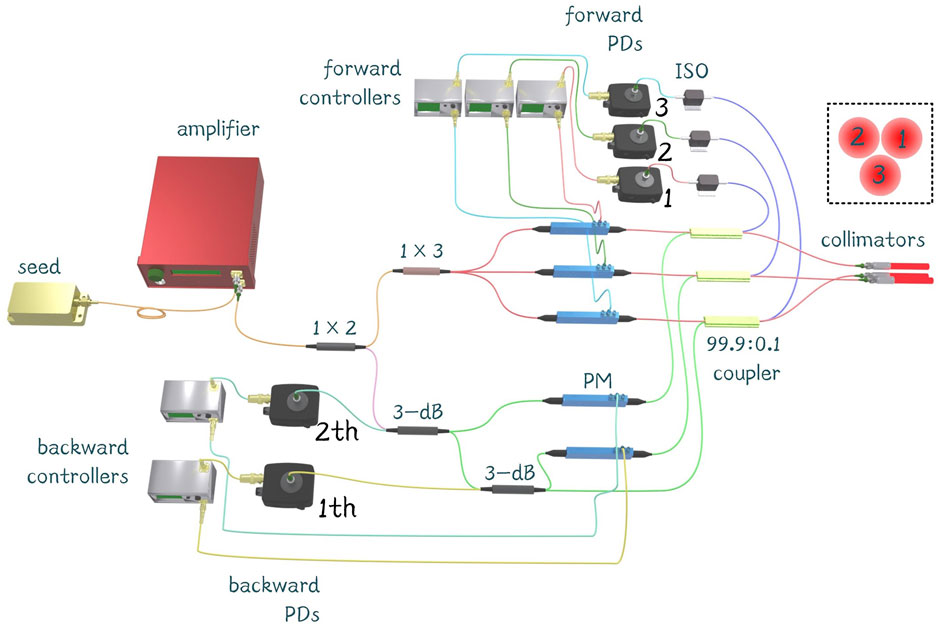
The experimental setup is shown in Figure 4. The principle has been illustrated in the Principle of Cascaded Internal Phase Control section. The seed laser is single frequency with a line width <10 MHz. As a proof-of-concept experiment, the sub-lasers are not amplified again, and the power of each sub-laser is ∼30 mW. In addition, there is a fiber isolator at the front of the PD of the forward loop to isolate the unwanted light reflected from the fiber tip. Another difference with Figure 1 is that the circulator in the measuring loop is not used in the proof-of-concept experiment as the power of the backward reflected light is low. The optical path difference (OPD) is not compensated for this experimental setup, but it is necessary to maintain the coherence between sub-lasers when increasing the power of sub-lasers, and a narrow line width seed is employed. The inset shows the arrangement of the three beams.
The PD signals of the three forward loops are shown in Figures 5A–C. When the forward loop is in the open loop, the interference signal is floating. When the forward loop is closed, the interference signal maintains at a high level. The PD signals of the two backward loops are shown in Figures 5D,E. The control strategy of the 2nd backward loop is to minimize the interference signal, as illustrated previously. When the 2nd backward loop is in the closed loop, the interference signal maintains a low level, as shown in Figure 5D. The light continues going back to the complementary arm and participates in interference of the 1st backward loop. For as long as there is a 3-dB coupler in the 1st backward loop, the control strategy keeps minimizing the interference signal. In a more-layer condition, the backward light in the first backward loop should be extracted by a circulator to prevent a lot of light going back to the seed, and the control strategy is to maximize the interference signal. The phase residue errors in the closed loops of Figures 5A–E are λ/29, λ/30, λ/27, λ/28, and λ/22, respectively.
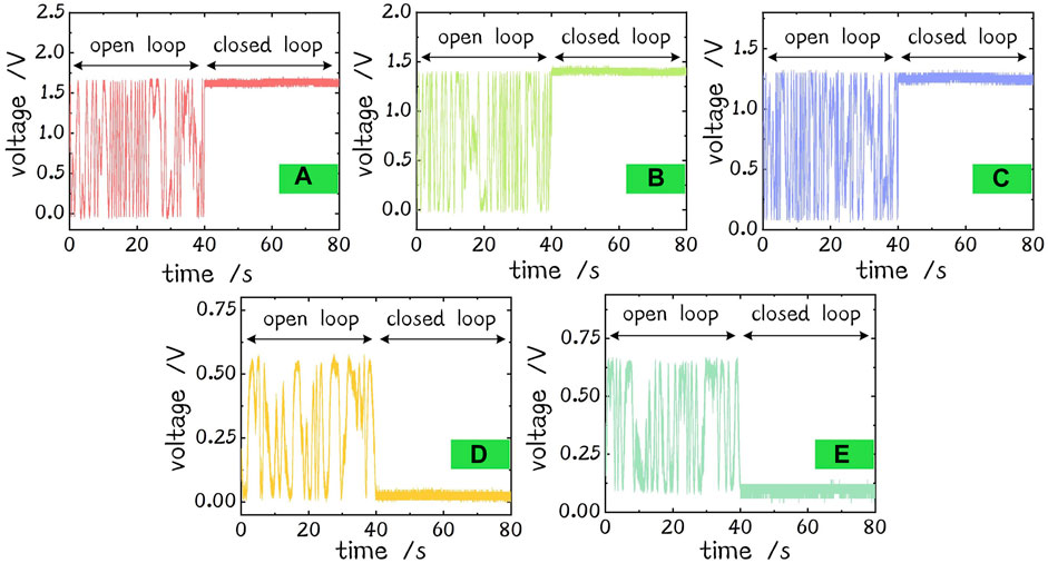
FIGURE 5. Signals of PDs. (A) Signal of forward loop 1. (B) Signal of forward loop 2. (C) Signal of forward loop 3. (D) Signal of the 2nd backward loop. (E) Signal of the 1st backward loop.
The phase residue error is calculated by
where φe is the phase residue error, Vmse is the mean square error, and Vmax is the max voltage of PD signal. The reason for increasing the phase residue error of the 2nd backward loop is that the backward light of beam 1 is too weak due to high insertion loss of elements such as PM (see the max voltage of open loop in Figures 5D,E; there is only ∼50 mV voltage rise in the same gain of PD, and the Vmax of the 2nd backward loop is 2.25 times higher than the 1st in the ideal case). Another reason affecting the phase residue error is the power line interference of the PD signal to increase Vmse. The frequency spectra of forward PD 1, 2, and 3 and backward PD 1, 2 are shown in Figures 6A–E. Figure 6F shows the average of them. There are peaks of 50 Hz and its harmonic wave in the open and closed loops. But the phase noise in the other frequency is suppressed in the closed loop still.
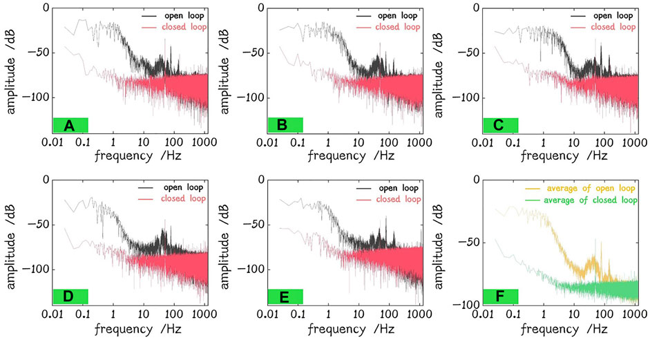
FIGURE 6. Frequency spectrum of PDs. (A) Forward PD 1. (B) Forward PD 2. (C) Forward PD 3. (D) Backward PD 1. (E) Backward PD 2. (F) Average.
When the system is in the closed loop, each phase update in the Gradient Descent Algorithm section represents the compensated phase. Summing up the value of the phase update, the phase during the closed loop can be obtained. The phases during 100 s closed loop of forward and backward loops are recorded and shown in Figure 7.
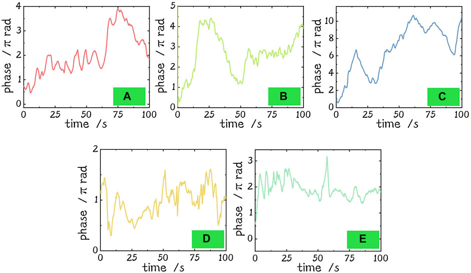
FIGURE 7. Phases of the forward and backward loops during 100 s in the closed loop. (A) Phase of forward loop 1. (B) Phase of forward loop 2. (C) Phase of forward loop 3. (D) Phase of the 2nd backward loop. (E) Phase of the 1st backward loop.
Based on the method in the Electric Control Method to Compensate π-ambiguity section, π-ambiguity is compensated, and the in-phase output of the three beams is obtained. The far-field patterns are shown in the Figure 8. When the system is in the open loop, the far-field pattern is blurred, as shown in Figure 8A. When the system is in the closed loop, the far-field pattern is clear and stable, as shown in Figure 8B, which is similar to the simulation result under ideal conditions shown in Figure 8C and shows the effectiveness of the structure. The interference fringes after the correction of π-ambiguity, as described in the Electric Control Method to Compensate π-ambiguity section of beams 1&3, beams 1&2, and beams 2&3, are shown in Figures 8D–F, respectively.
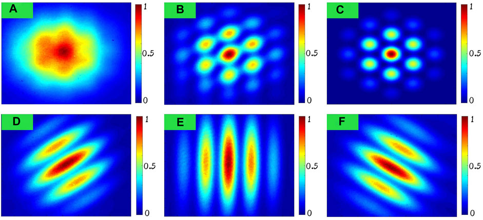
FIGURE 8. 40s long-exposure far-field patterns. (A) Open loop. (B) Closed loop. (C) Simulation. (D) Interference fringe of beams 1&3. (E) Interference fringe of beams 1&2. (F) Interference fringe of beams 2&3.
As the π phase can be added electrically, different interference patterns will be generated by injecting the π phase to the specified beam. Figure 9 shows the far-field patterns with different phases of 0 or π. Figure 9A1 shows the pattern of far-field with [0, π, 0] phases of beams 1–3, and the simulation result is shown in Figure 9A2. Similarly, the phases of three beams in Figures 9B,C are [0, 0, π] and [π, 0, 0]. As the figures in the first row of Figure 9 are 40 s long-exposure pictures of the experiment, there is longitudinal fuzzy due to the vertical vibration of the test bed.
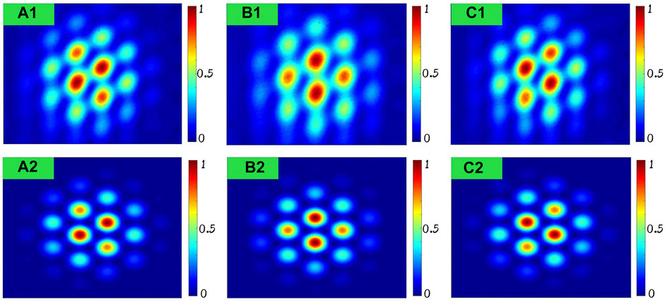
FIGURE 9. Far-field patterns of different phases. (A) Experiment and simulation results of [0, π, 0] the phases of beams 1–3. (B) Experiment and simulation results of [0, 0, π] phases of beams 1–3. (C) Experiment and simulation results of [π, 0, 0] phases of beams 1–3.
Conclusion
In this article, we proposed a cascaded active phase-locking method of an all-fiber structured laser array. The principle of cascaded phase-locking is illustrated, and the gradient descent algorithm is introduced. Three beams are coherently combined by this method. The phase noise is compensated, and the phase residue error is better than λ/22. For the characteristic of the principle, π-ambiguity needs to be compensated manually by adding π voltage to the phase modulator by the phase controller, according to the interference fringe of two beams for now. Additionally, different far-field patterns can be generated by injecting π phase in some channels. Compared to our previous work, the structure increases the channel- scaling ability and enhances the ability of electric control to compensate π-ambiguity. The cascaded structure can also be combined with non-cascade common port feedback phase-locking to achieve group phase control to increasing combining channel while maintaining the bandwidth of a group. The fiber laser array presented has the potential to be applied to generate structure light field and achieve a combination of the vector beam. The future works are focused on the expansion of array, solutions of π-ambiguity automatically, and power scaling.
Data Availability Statement
The original contributions presented in the study are included in the article/Supplementary material; further inquiries can be directed to the corresponding authors.
Author Contributions
All authors listed have made a substantial, direct, and intellectual contribution to the work and approved it for publication.
Funding
This work was supported by the National Natural Science Foundation of China (62075242), the Innovative Research Groups of Hunan Province (2019JJ10005), and the Training Program for Excellent Young Innovators of Changsha (KQ2106005).
Conflict of Interest
The authors declare that the research was conducted in the absence of any commercial or financial relationships that could be construed as a potential conflict of interest.
Publisher’s Note
All claims expressed in this article are solely those of the authors and do not necessarily represent those of their affiliated organizations, or those of the publisher, the editors, and the reviewers. Any product that may be evaluated in this article, or claim that may be made by its manufacturer, is not guaranteed or endorsed by the publisher.
References
1. Zervas MN, Codemard CA. High Power Fiber Lasers: A Review. IEEE J Select Top Quan Electron. (2014) 20(5):219–41. doi:10.1109/JSTQE.2014.2321279
2. Jauregui C, Limpert J, Tünnermann A. High-Power Fibre Lasers. Nat Photon (2013) 7(11):861–7. doi:10.1038/nphoton.2013.273
3. Stihler C, Jauregui C, Kholaif SE, Limpert J. Intensity Noise as a Driver for Transverse Mode Instability in Fiber Amplifiers. PhotoniX (2020) 1(1):8. doi:10.1186/s43074-020-00008-8
4. Liu Z, Ma P, Su R, Tao R, Ma Y, Wang X, et al. High-Power Coherent Beam Polarization Combination of Fiber Lasers: Progress and Prospect [Invited]. J Opt Soc Am B (2017) 34(3):A7–A14. doi:10.1364/JOSAB.34.0000A7
5. Duplay E, Bao ZF, Rodriguez Rosero S, Sinha A, Higgins A. Design of a Rapid Transit to Mars Mission Using Laser-Thermal Propulsion. Acta Astronautica (2022) 192:143–56. doi:10.1016/j.actaastro.2021.11.032
6. Parkin KLG. The Breakthrough Starshot System Model. Acta Astronautica (2018) 152:370–84. doi:10.1016/j.actaastro.2018.08.035
7. Bandutunga CP, Sibley PG, Ireland MJ, Ward RL. Photonic Solution to Phase Sensing and Control for Light-Based Interstellar Propulsion. J Opt Soc Am B (2021) 38(5):1477–86. doi:10.1364/JOSAB.414593
8. Worden SP, Green WA, Schalkwyk J, Parkin K, Fugate RQ. Progress on the Starshot Laser Propulsion System. Appl Opt (2021) 60(31):H20–3. doi:10.1364/AO.435858
9. Mourou G, Brocklesby B, Tajima T, Limpert J. The Future Is Fibre Accelerators. Nat Photon (2013) 7(4):258–61. doi:10.1038/nphoton.2013.75
10. Goodno GD, McNaught SJ, Rothenberg JE, McComb TS, Thielen PA, Wickham MG, et al. Active Phase and Polarization Locking of a 14 kW Fiber Amplifier. Opt Lett (2010) 35(10):1542–4. doi:10.1364/OL.35.001542
11. Fsaifes I, Daniault L, Bellanger S, Veinhard M, Bourderionnet J, Larat C, et al. Coherent Beam Combining of 61 Femtosecond Fiber Amplifiers. Opt Express (2020) 28(14):20152–61. doi:10.1364/OE.394031
12. Ma Y, Wang X, Leng J, Xiao H, Dong X, Zhu J, et al. Coherent Beam Combination of 108 kW Fiber Amplifier Array Using Single Frequency Dithering Technique. Opt Lett (2011) 36(6):951–3. doi:10.1364/OL.36.000951
13. Shay TM, Benham V, Baker JT, Sanchez AD, Pilkington D, Lu CA. Self-Synchronous and Self-Referenced Coherent Beam Combination for Large Optical Arrays. IEEE J Select Top Quan Electron. (2007) 13(3):480–6. doi:10.1109/JSTQE.2007.897173
14. Ahn HK, Kong HJ. Cascaded Multi-Dithering Theory for Coherent Beam Combining of Multiplexed Beam Elements. Opt Express (2015) 23(9):12407–13. doi:10.1364/OE.23.012407
15. Klenke A, Müller M, Stark H, Tünnermann A, Limpert J. Sequential Phase Locking Scheme for a Filled Aperture Intensity Coherent Combination of Beam Arrays. Opt Express (2018) 26(9):12072–80. doi:10.1364/OE.26.012072
16. Hou T, An Y, Chang Q, Ma P, Li J, Zhi D, et al. Deep-Learning-Based Phase Control Method for Tiled Aperture Coherent Beam Combining Systems. High Pow Laser Sci Eng (2019) 7(4):e59. doi:10.1017/hpl.2019.46
17. Liu R, Peng C, Liang X, Li R. Coherent Beam Combination Far-Field Measuring Method Based on Amplitude Modulation and Deep Learning. Chin Opt Lett (2020) 18(4):041402. doi:10.3788/COL202018.041402
18. Tünnermann H, Shirakawa A. Deep Reinforcement Learning for Coherent Beam Combining Applications. Opt Express (2019) 27(17):24223–30. doi:10.1364/OE.27.024223
19. Du Q, Zhou T, Doolittle LR, Huang G, Li D, Wilcox R. Deterministic Stabilization of Eight-Way 2d Diffractive Beam Combining Using Pattern Recognition. Opt Lett (2019) 44(18):4554–7. doi:10.1364/OL.44.004554
20. Vorontsov MA, Carhart GW, Ricklin JC. Adaptive Phase-Distortion Correction Based on Parallel Gradient-Descent Optimization. Opt Lett (1997) 22(12):907–9. doi:10.1364/OL.22.000907
21. Geng C, Luo W, Tan Y, Liu H, Mu J, Li X. Experimental Demonstration of Using Divergence Cost-Function in Spgd Algorithm for Coherent Beam Combining with Tip/Tilt Control. Opt Express (2013) 21(21):25045–55. doi:10.1364/OE.21.025045
22. Weyrauch T, Vorontsov MA, Carhart GW, Beresnev LA, Rostov AP, Polnau EE, et al. Experimental Demonstration of Coherent Beam Combining over a 7 Km Propagation Path. Opt Lett (2011) 36(22):4455–7. doi:10.1364/OL.36.004455
23. Montoya J, Augst SJ, Creedon K, Kansky J, Fan TY, Sanchez-Rubio A. External Cavity Beam Combining of 21 Semiconductor Lasers Using Spgd. Appl Opt (2012) 51(11):1724–8. doi:10.1364/AO.51.001724
24. Du Q, Wang D, Zhou T, Li D, Wilcox R. 81-Beam Coherent Combination Using a Programmable Array Generator. Opt Express (2021) 29(4):5407–18. doi:10.1364/OE.416499
25. Chang H, Chang Q, Xi J, Hou T, Su R, Ma P, et al. First Experimental Demonstration of Coherent Beam Combining of More Than 100 Beams. Photon Res (2020) 8(12):1943–8. doi:10.1364/PRJ.409788
26. Shpakovych M, Maulion G, Kermene V, Boju A, Armand P, Desfarges-Berthelemot A, et al. Experimental Phase Control of a 100 Laser Beam Array with Quasi-Reinforcement Learning of a Neural Network in an Error Reduction Loop. Opt Express (2021) 29(8):12307–18. doi:10.1364/OE.419232
27. Bowman DJ, King MJ, Sutton AJ, Wuchenich DM, Ward RL, Malikides EA, et al. Internally Sensed Optical Phased Array. Opt Lett (2013) 38(7):1137–9. doi:10.1364/OL.38.001137
28. Hettel W, Meinhold P, Suen JY, Srinivasan P, Krogen P, Wirth A, et al. Beam Propagation Simulation of Phased Laser Arrays with Atmospheric Perturbations. Appl Opt (2021) 60(17):5117–23. doi:10.1364/AO.422337
29. Vorontsov MA, Lachinova SL, Beresnev LA, Weyrauch T. Obscuration-Free Pupil-Plane Phase Locking of a Coherent Array of Fiber Collimators. J Opt Soc Am A (2010) 27(11):A106–A21. doi:10.1364/JOSAA.27.00A106
30. Kolosov VV, Levitskii ME, Petukhov TD, Simonova GV. Formation of the Feedback Loop for Phase Control of a Fiber Laser Array. Atmos Ocean Opt (2019) 32(6):716–23. doi:10.1134/S1024856019060095
31. Roberts LE, Ward RL, Francis SP, Sibley PG, Fleddermann R, Sutton AJ, et al. High Power Compatible Internally Sensed Optical Phased Array. Opt Express (2016) 24(12):13467–79. doi:10.1364/OE.24.013467
32. Sibley PG, Ward RL, Roberts LE, Francis SP, Shaddock DA. Crosstalk Reduction for Multi-Channel Optical Phase Metrology. Opt Express (2020) 28(7):10400–24. doi:10.1364/OE.388381
Keywords: coherent beam combining, internal phase-locking, fiber laser array, gradient descent algorithm, laser field manipulation
Citation: Chang H, Su R, Zhang Y, Jiang M, Chang Q, Long J, Ma P, Ma Y and Zhou P (2022) Cascaded Internal Phase Control of All-Fiber Coherent Fiber Laser Array. Front. Phys. 10:913195. doi: 10.3389/fphy.2022.913195
Received: 05 April 2022; Accepted: 02 May 2022;
Published: 08 June 2022.
Edited by:
Shiyao Fu, Beijing Institute of Technology, ChinaReviewed by:
Zhen Yang, China South Industries Research Academy, ChinaRui Min, Beijing Normal University, China
Pingxue Li, Beijing University of Technology, China
Copyright © 2022 Chang, Su, Zhang, Jiang, Chang, Long, Ma, Ma and Zhou. This is an open-access article distributed under the terms of the Creative Commons Attribution License (CC BY). The use, distribution or reproduction in other forums is permitted, provided the original author(s) and the copyright owner(s) are credited and that the original publication in this journal is cited, in accordance with accepted academic practice. No use, distribution or reproduction is permitted which does not comply with these terms.
*Correspondence: Rongtao Su, c3Vyb25ndGFvQDEyNi5jb20=; Pu Zhou, emhvdXB1MjAzQDE2My5jb20=
 Hongxiang Chang
 Rongtao Su*
 Yuqiu Zhang