- Department of Modern Mechanics, CAS Key Laboratory of Mechanical Behavior and Design of Material, University of Science and Technology of China, Hefei, China
Inspired by notions of topological physics, recent years have witnessed the rapid development of mechanical metamaterials with novel properties of topological states. However, most of the current investigations have either focused on discrete mass-spring lattices, with topological states limited to a single operating band, or on various elaborate continuous elastic systems, enduring the drawbacks of modal couplings. It remains largely unexplored how to design topological elastic systems that naturally possess multiple operating bands and are free from modal couplings. In this study, we design an elastic system based on fundamental mechanical elements (beams, rods and nuts), which is capable of supporting multiband pure topological states. Through an equivalent beam-spring model with lumped masses together with finite element analysis, we demonstrate that our proposed structure exhibits multiple Dirac points (DPs) at different frequencies. We show that simply adjusting the heights of nuts fastened on beams can lift the degeneracies, giving rise to two kinds of valley Hall phases characterized by opposite valley Chern numbers. The dispersion diagram of the supercell formed by unit cells with different topological indices shows that there simultaneously exist perfectly pure interface modes (i.e., no other modes coexist) within two frequency ranges. Furthermore, numerical simulations demonstrate that the domain wall formed by structures with distinct topological properties supports topologically protected interface waves over dual frequency ranges. Our results have potential for the design of mechanical systems that need to work under changeable working frequencies and may have significant impact on many diverse fields such as vibration control, energy harvesting and seismic isolation.
1 Introduction
In the last decade, the discovery and extensive study of topological insulators in condensed matters [1] have brought innovative ideas to the design of classical wave systems with novel properties [2]. In electronic systems, non-trivial topological phases, manifested by robust and backscattering-free boundary states [3], are generally characterized by topological invariants, e.g., Chern numbers, which are defined by the eigenstates on energy bands [4]. The concept of band structure has also been introduced and largely studied in various artificial periodical structures such as photonic crystals [5] and phononic crystals [6]. Consequently, various concepts in topological physics are naturally introduced into classical wave systems [2], which provides many unprecedented new avenues for wave manipulation [7], energy harvesting [8] and information transfer [9]. In return, taking advantage of scalability and controllability, classical wave systems, e.g., acoustic crystals and mechanical structures, provide powerful and versatile platforms for probing into topological physics and related unusual phenomena [10].
Robust topological states exist at interface between phases with distinct topological invariants [11]. Despite the origin of the topological states varies dramatically in the existing proposed structures, the common requirement in their realization is breaking a certain kind of symmetry, namely, temporal or spatial symmetry [12]. For example, analogous to quantum Hall effect [13], active components [14–16], the application of an external field [17–19] and synthetic gauge fields [20, 21], have been widely exploited to break time-reversal symmetry, opening topological bandgaps that support one-way edge modes. These approaches make the system complicated and obviously difficult to implement in practice. Recently, spatial symmetry have been proven to be one of the most accessible way to achieve non-trivial topological phases, since it relies on simple manipulating the symmetry of the underlying lattice. For instance, quantum spin Hall effect has been emulated by solely changing the geometric parameters of the structure [22, 23], which breaks the point group symmetry and results in topologically non-trivial bandgap sustaining two dispersive edge states with opposite propagation directions [19, 24, 25]. Particularly, simple rotation or mirror operations have succeeded in realizing topological interface states based on valley Hall effect [26–30]. Here, we propose a way to trigger the valley Hall phase transition by adjusting the nuts fastened on Euler-Bernoulli (EB) beams, which is amenable to practical implementation.
In spite of the fact that great achievements have been made in designing mechanical systems possessing topological states, the majority of those investigations have focused on discrete mass-spring systems [14, 19, 31–33]. Thanks to its structural simplicity, these discrete systems are excellent candidates for illustrating abundant topological essentials associated with various exotic phenomena [34, 35]. In particular, the resulting topological interface modes hosted by mass-spring lattices are ideally pure, meaning that there are no additional trivial bands coexisting within the same frequency range [19, 31]. This monomodal feature is beneficial to witness highly identifiable interface guided wave propagation without any interference. Nevertheless, the difficulty of transfer to practical configurations and the nature of limited degree of freedom induced frequency band singleness [19, 27, 31] make the discrete systems hopeless of practical applications. In recent years, tremendous efforts have been devoted to achieving topological elastic wave transmission in various continuous elastic systems [7, 36–40]. Unlike discrete systems, continuous structures often possess a wide range of frequency bands due to their infinite degree of freedom [41]. In terms of potential application, this multimodal feature offers a tremendous degree of flexibility in controlling wave dynamic response, providing opportunities for designing structures possessing broadband or multiband topologically protected waves [42–46]. However, the nature of multimode inevitably leads to a hybrid of the bands inside the topological bandgaps, which can severely impedes the performance of interface states [38, 40, 47]. In other words, ubiquitous modal couplings greatly increases the complexity and difficulty of topological band engineering for elastic waves [45, 46]. From these points of view, designing elastic structures with topological states featuring a combination of multiple bands (i.e., with multiple working frequency ranges) and purity (i.e., free from modal hybridization) remains elusive and is rarely studied in the present literature.
In this paper, we design an elastic system composed of fundamental mechanical elements (beams, rods and nuts), which is capable of supporting pure topological states over multi-frequency ranges. Through an equivalent beam-spring model and finite element analysis, we demonstrate that the honeycomb structure composed of EB beams exhibits multiple Dirac degeneracy points at different frequencies, and adjusting the heights of nuts fastened on beams can lift the degeneracies, giving rise to two kinds of valley Hall phases characterized by opposite valley Chern numbers. Dispersion analysis of the supercell constructed by unit cells with distinct topological indices together with numerical simulations for a finite-size structure demonstrate that the domain wall formed by structures belonging to distinct topological phases supports interface waves at dual frequency ranges, which are topologically protected manifested by the feature of being immune to backscattering of sharp corner. The present study can improve the shortcomings of the most existing phononic topological insulators with only a single operating band, and is expected to open up the possibility for the realization of frequency switchable topological states.
2 Methods
This section presents the free vibration analysis for the proposed elastic honeycomb structure based on theoretical model and finite element method (FEM).
2.1 Beam-Spring Model With Lumped Masses
Considering the preconditions for the emergence of DPs [48], we construct a honeycomb lattice structure using congruent circular columns coupled with each other via slender rods, as shown in Figure 1A, where, each column is equipped with two nuts whose spacing is adjustable. Note that all the nuts are identical, and colors red and green are only used to distinguish nonequivalent sites within one unit cell. In order to facilitate theoretical analysis, we propose an equivalent beam-spring model to simplify the honeycomb lattice structure, where, the circular columns are considered as EB-beams, the slender rods are regarded as the massless springs and the nuts are replaced by lumped masses, as shown in Figure 1B. A theoretical framework based on the beam-spring model for the transverse free vibration analysis will be elaborated, which will be applied to calculation of the band structure of the infinite honeycomb lattice.
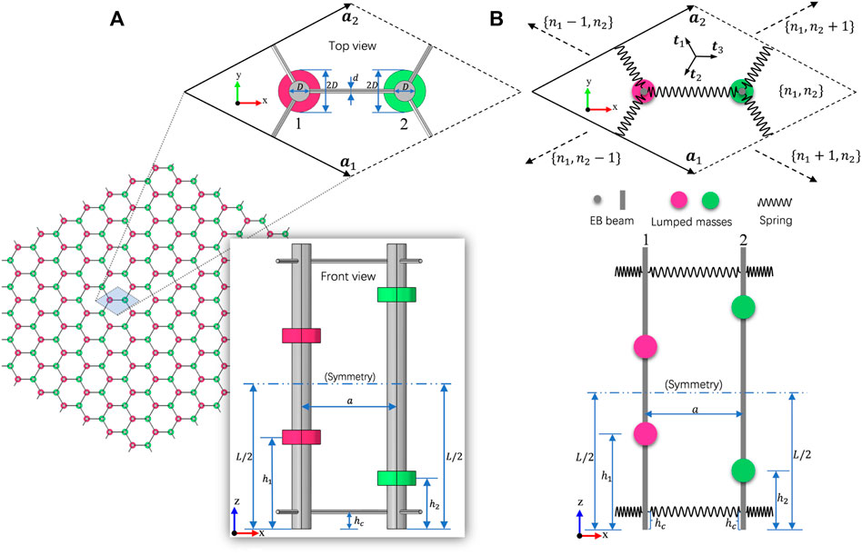
FIGURE 1. (A) Elastic honeycomb lattice arranged by congruent circular columns placed in parallel alignment and connected by slender rods at two free ends, each column is equipped with two nuts (denoted by red or green oblate column). The dotted rhombus shows the top view of the unit cell composed of two sites labeled 1 and 2, the inset shows the front view of the unit cell, which is arranged symmetrically up and down (B) The top view and front view of a unit cell located at the site {n1, n2} of the equivalent beam-spring model, where, lumped masses represent the nuts in (A), t1, t2 and t3 are three direction vectors of connecting springs, a1 and a2 are two basis vectors of the lattice.
2.1.1 Governing Equations
Considering an arbitrary unit cell located at the site
where
where
Using the time-harmonic assumption, i.e., wi = Wi exp (iωt), vi = Vi exp (iωt), Eq. 1 can be rewritten as:
where ω is the angular frequency, the capital symbols (W and V) represent the corresponding time-harmonic solutions of Eq. 1,
2.1.2 Bloch’s Theorem
For free vibration analyses in an infinite periodic lattice, Bloch’s theorem states that the time-harmonic solution of the equation of motion can be written as a periodic function with a spatial modulation [49], that is,
where k is the Bloch wave vector and U(x) is periodic with respect to the basis vectors of the lattice, hence satisfies
In this case, Eq. 5 leads to the well-known Floquet-Bloch condition:
hereinafter, notations p = exp (ik ⋅a1) and s = exp (ik ⋅a2) are adopted for the sake of brevity.
Note that Bloch’s theorem allows the vibration response of an infinite and periodic structure to be completely described through the governing equations for a unit cell, with suitable boundary conditions. The properties at any other location can be related to those of this very unit cell according to the formula expressed by Eq. 6.
By employing the Bloch’s theorem, our governing equation Eq. 4 will turn into:
with
where
have been used, the superscript (∗) denotes complex conjugation, and
with
where
2.1.3 Eigenvalue Problem
In order to obtain the eigenvalue problem associated with the free vibration problem presented above, we use Galerkin method and the superposition of modes [50] to deal with Eq. 9, in which the time-harmonic Bloch solutions can be expressed as:
where trial functions
where, ψ denotes the eigenvector, formed by the assembly of unknown coefficients in Eq. 11, i.e.,
and, accordingly,
in which,
with ω0(n) (n = 1, 2, … , N) being the nth order natural angular frequency of the free-free EB beam, corresponding to the normalized natural modes
and the matrix
Eq. 12 is equivalent to the well-known generalized eigenvalue problem:
with K = Ω − S,
2.2 Finite Element Model
2.2.1 Irreducible Brillouin Zone
In general, to obtain the band structures, we have to sweep every wave vector k in the first Brillouin zone (BZ) of the reciprocal space, spanned by the basis vectors expressed as:
where
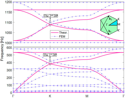
FIGURE 2. Band structures of the honeycomb lattice arranged with unperturbed unit cells with all the nuts being fastened at the same height on the beams, obtained by theoretical model and FEM, exhibit two degenerate Dirac points at frequencies around 400 Hz and 1,100 Hz. The inset shows the IBZ (the cyan area) together with reciprocal basis vectors b1 and b2.
Following the ideas of the theoretical method proposed in Sec. 2.1, solutions of displacement fields of the two beams within one unit cell are all expanded by the trial function truncated to order N [i.e., Eq. 11]. Then for each point along Γ-K-M-Γ, the eigenvalue problem Eq. 14 need to be solved to obtain the corresponding natural angular frequency ω and eigenvector ψ.
2.2.2 Finite Element Analysis
In this study, we perform finite-element simulations for the elastic waves in the honeycomb lattice structures using COMSOL Multiphysics with the solid mechanics module. The solid honeycomb lattice model is established, shown as in Figure 1A, where the material of two circular columns and nuts is selected as aluminum (Eal = 70 GPa, ρal = 2,700 kg/m3 and νal = 0.33) and that of slender connecting rods is nylon (Eny = 2 GPa, ρny = 1,150 kg/m3 and νny = 0.4). Throughout this paper, the diameter of the slender rods is set to be d = 0.4 cm, and that for the circular columns is D = 2 cm. The nuts denoted by oblate columns have a diameter of 2D and a height of hn = 1.5 cm. All other parameters needed in modeling can be found in Table 1. We calculate the band structure of the infinite and periodic honeycomb structure using a single unit cell, wherein the Floquet-Bloch periodic boundary condition is applied in both the a1 and a2 directions. The eigenfrequency study is performed for every wave vector k scanned along the boundaries of the IBZ whose edges are expressed as Eq. 16.
3 Results and Discussion
3.1 Multiple Dirac Points
We first consider a periodic honeycomb structure in which the nuts on the left and right beams are fastened at the same height, i.e., h1 = h2 = h0, with h0/L = 0.25, where L is the length of the beam. Other unknown parameters are listed in Table 1. Note that the cross-sectional moment of inertia of the beam I = πD4/64, the equivalent stiffness of the connecting spring ks = Enyπd2/[4 (a − D)] and the equivalent lumped mass m = ρalπ[(2D)2 − D2]hn/4 are all obtained corresponding to the parameters adopted in the finite element model.
Figure 2 demonstrates the band structure of the initial unit cell with h1 = h2 = h0, obtained by theoretical method based on the equivalent beam-spring model and FEM. Despite some slight differences, which was caused by neglecting the bending action of slender rods in the equivalent beam-spring model, the theoretical results and FEM both show two Dirac degeneracy points at frequencies around 400 and 1,100 Hz at K point. It is worth noting that the emergency of DPs is ensured by C3v symmetry of the underlying lattice [48], while the multiplicity of DPs is attributed to the multimode characteristic of transverse free vibration of beams (referring to the mode shapes displayed in Figure 5). Since that the emergency of DP is the prerequisite for engineering valley Hall phases [51], one can expect to achieve topological states within the dual working frequency ranges by simultaneously gaping the two DPs aforementioned. This will be detailed below.
3.2 Mirror Symmetry Breaking and Topological Phase Transition
It has been widely recognized that the Dirac degeneracy can be lifted by breaking spatial symmetries [48], which provide simple ways to achieve topological order. In this study, we break the mirror symmetry of the primitive lattice by adjusting the fastening heights of nuts such that h1 is no longer equal to h2. We define the strength of perturbation as:
where h0 is the initial height of the nuts fastened on both the left and right beams. Note that h1 and h2 deviate from the unperturbed value h0 with the same perturbation strength but opposite sign. In this case, two different symmetry-invariant configurations of the perturbed unit cell, shown as Cell A (β > 0) and Cell B (β < 0) in Figure 3, are created by breaking the mirror symmetry in two opposite ways.
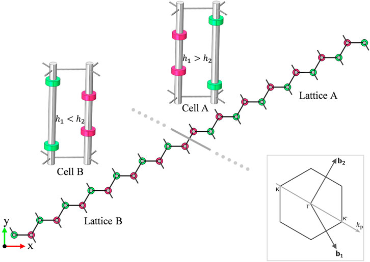
FIGURE 3. Top view of the supercell formed by connecting 7 type-A unit cells (h1> h2) and 7 type-B unit cells (h1< h2) on both sides of the interface (the thick gray line) (Throughout this paper, we use colors red and green to distinguish layouts of the two nuts fastened on the two columns within a unit cell.) The inset gives the direction of the wave vector kp along which the projected band structure of the supercell would be calculated.
Figure 4A demonstrates the band structures of the honeycomb lattice arranged with unit cells of type-A (with β = 0.076), obtained by both the theoretical method and FEM. We can notice that the splittings of the two DPs occur and two complete bandgaps (indicated by cyan and gray region) emerge at frequencies around 400 Hz and 1,050 Hz. The consistency of bandgap widths shows again that the theoretical model is in good agreement with FEM.
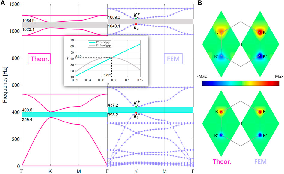
FIGURE 4. (A) Band structures of the honeycomb lattice arranged with unit cells of type A (with β =0.076), obtained by theoretical model and FEM, exhibit splittings of the Dirac points and two complete bandgaps at frequencies around 400 and 1,050 Hz. The red (
Interestingly, we find that the two bandgap widths show dramatically different trends with the adjustment height of the nuts (i.e., with different values of β). The inset of Figure 4A displays the evolution of bandgap widths as functions of β, wherein Δf quantifies the frequency difference between
We emphasize that this provides an accessible way to tune the bandgaps (namely, the operating frequency ranges of the topological states shown in the following text). Specifically, if we adjust the fastening heights of the nuts such that the perturbation strength β is larger than 0.076, then the lower frequency bandgap is dominant; while for β smaller than 0.076, the higher frequency bandgap dominates.
By analogy with the valley in quantum systems [26], two pairs of states of two band extreme at K point called as valley states appear near the two lifted DPs respectively, denoted by
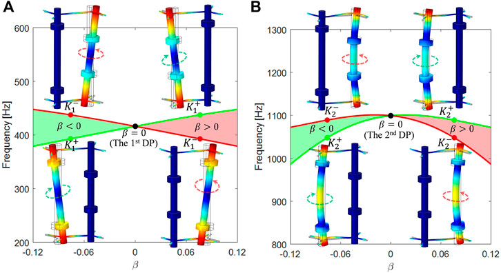
FIGURE 5. (A) Evolution of bounding frequencies
In addition, topological phase transition with the sign of β flipping can be quantitatively inferred by the valley Chern number, which is an index to characterize the topological nature of the band [27, 33] and obtained by integrating the Berry curvature over an individual valley, expressed as:
where, v = K(K′) is the BZ corner, the integration domain BZ(v) is a local area near the point v, and
where sgn(β) means the sign of β, herein depends on the relative fastening height of the nuts on the left (h1) and right (h2) beam. Due to the fact that the two types of unit cell possess the opposite sign of β (see Figure 3), one can immediately realize that the valley Chern numbers of them also have opposite signs, representing two distinct valley Hall phases. For the sake of verification, we calculate the Berry curvature around valleys by the numerical method [14], using the eigenvectors stemming from the theoretical model and Bloch eigenmodes from FEM, respectively. For β = 0.076, the combined Berry curvatures associated with both the two bands above the two bandgaps are shown in Figure 4B (calculation details are presented in Supplementary Material). For both the results from our theoretical model and FEM, the integral of the Berry curvature over the full BZ is precisely zero with the total Chern number C = 0, which is ensured by time-reversal symmetry [3]. For both lower and higher frequency bands, the associated Berry curvatures are prominently localized near valleys K and K′, and feature exactly the same amplitude but opposite signs with respect to K and K′. By integrating these Berry curvatures (taking the results from FEM as an example), we obtain the valley Chern numbers CK(K′) = +(−)0.37 (lower bands) and CK(K′) = +(−)0.29 (higher bands). Recalling that, endowed with ± β, the two types of unit cell are symmetry-invariant, implying that K(K′) for type-A unit cell is just equivalent to K′(K) for type-B. Therefore, if CK = +0.37 (+0.29) characterizes the topological properties associated to the first (second) bandgap for type-A unit cell, then CK′ = −0.37 (−0.29) corresponds to type-B unit cell. In spite of apparent discrepancy between numerical valley Chern numbers and the theoretical predictions (±1/2), the different signs, + and −, clearly distinguish different valley Hall phases.
It is worth emphasizing that, although we only care about type-A unit cell above, the type-B unit cell with opposite value of perturbation strength (β = −0.076) has exactly the same dispersion diagram as that of A, though band inversion is implied with the eigenmodes associated with the corresponding valley states flipped [27], which echoes the opposite valley Chern numbers aforementioned. Therefore, topological phase transition occurs when we cross the domain wall between lattices formed by type-A and type-B unit cells, and according to the bulk-edge correspondence [1], topological states are bound to appear in the two bandgaps shared in common by these two lattices.
3.3 Interface Modes
To verify the existence of elastic valley Hall interface states, we consider a strip supercell composed of 14 unit cells with different topological valley Hall phases at either side of the interface, as shown in Figure 3. Note that the supercell is arranged periodically along the a1 direction, with periodicity
The corresponding band structure of the strip supercell is presented in Figure 6A, wherein the color bar indicates the degree of localization of the mode at the interface by making a ratio α between the average displacement nearby the interface and in the whole supercell, defined as:
where I2 represents two unit cells on each side of the interface, SC means the whole supercell, and ux, uy, uz are three displacement components in x, y, and z axis, respectively. Notably, α would be close to 1 (red) for modes localized near the interface and much less than 1 or near 0 (blue) for bulk modes.
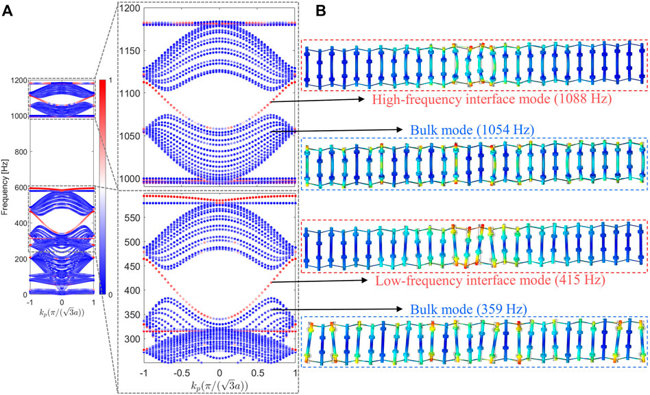
FIGURE 6. (A) Band structure of the supercell consisting of two distinct topological phases (shown as Figure 3, with β =±0.076). Colour indicates the degree of interface confinement of the eigenmodes, defined by the ratio α in Eq. 20. The enlarged band diagram clearly shows perfectly pure interface modes (i.e., no other modes coexist) spanning the two bandgaps, highlighted by red dots (B) Displacement fields of the interface modes at two frequency ranges indicated by black arrows, together with those of the bulk modes.
From the enlarged view of the band structure, we can find that the interface modes (denoted by the red dots) appear simultaneously in the overlapping bulk bandgaps discussed above, with working frequencies around 400 Hz and 1,050 Hz. It is worth noting that the interface modes spanning the two bandgaps are perfectly pure, namely, no other modes coexist at the same frequency ranges. This extraordinary feature, as one of the essential points of this paper, has rarely been reported and can hardly been realized in the existing topological elastic structures wherein modal hybridization is ubiquitous and unavoidable [2].
In order to demonstrate the localized properties of the interface modes, we plot the displacement fields for some typical eigenmodes evaluated at four frequencies indicated by the black arrows, as shown in Figure 6B. It can be seen clearly that, for the interface mode, either in low-frequency or high-frequency range, only beams close to the interface have a strong vibration, while all the beams of the supercell have considerable displacement amplitude for the bulk mode. What’s more, it is worth observing that both the low-frequency and high-frequency interface modes are gapless, signifying that two bandgaps resulted from the splittings of DPs (see Sec. 3.2) are just the expected operating frequency ranges of the topological elastic waves.
3.4 Topologically Protected Interface States at Multi-Working Frequencies
To gain further insight into the topological interface states observed in the previous section, we construct a typical configuration with zigzag waveguide (shown as the top-left panel of Figure 7) to carry the numerical simulation of topological elastic wave propagation property. Simulations are carried by the frequency domain study of solid mechanics in the COMSOL. During the simulation, tips of the two beams located near the black star are subjected to a horizontal harmonic displacement excitation with some specified frequency, while other beams and nuts, including those on the boundaries, are all set free. The displacement fields, indicating the dynamic response, are drawn to reveal the characteristics of the wave propagation at this very frequency.
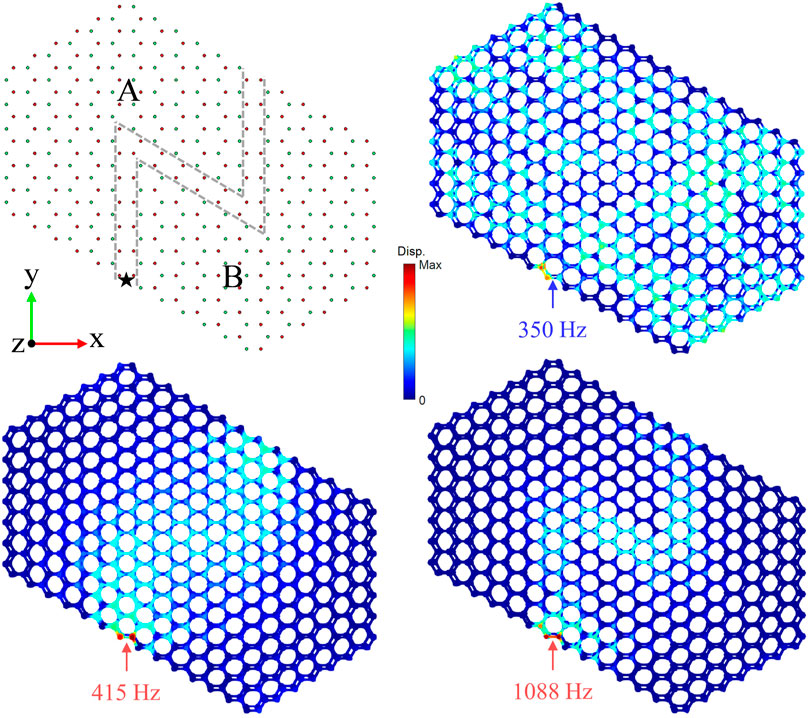
FIGURE 7. A topological configuration with a zigzag interface separated by lattices A and B (top-left panel), in which the black star indicates the excitation point. Displacement fields of interface states within low-frequency range (bottom-left panel) and high-frequency range (bottom-right panel), excited with frequency 415 Hz and 1,088 Hz, respectively. Displacement field of bulk states (top-right panel) is also shown for comparison, excited with frequency 350 Hz.
The contours of displacement fields of dynamic responses correspond to the excitation frequencies 415 Hz and 1,088 Hz are displayed in the bottom-left and bottom-right panels of Figure 7, respectively. As we can see, for both lower and higher frequencies, elastic waves are localized and can pass the zigzag interface without any hindrance. This is exactly what we expected since the two excitation frequencies are both located in the bandgaps in which the valley Hall interface modes occupy, as we demonstrated in Sec. 3.3. For comparison, we map the dynamic response displacement field for excitation frequency 350 Hz, corresponding to the bulk band, as displayed in the top-right panel of Figure 7. Unlike the former cases in which displacement fields are concentrated near the interface, for the bulk band frequency, the structure experiences almost a full-field dynamic response. These results are in complete agreement with the previous dispersion analysis, and provide strong evidence that our proposed structure supports topological elastic wave propagation with multi-working frequencies.
4 Conclusion
This study present a strategy to design elastic structures exhibiting pure topological states over multi-frequency ranges. We proposed an equivalent beam-spring model with lumped masses for investigating dispersion relations of the designed structures, together with numerical simulations using FEM for verification. The band structures for the initial unit cell obtained by these two ways, agreeing well with each other, document two Dirac points at different frequencies. The emergence of these deterministic Dirac points is ensured by the C3v symmetry of the underlying lattice and the multiplicity is attributed to the nature of multi-order natural modes of the EB beams consisting our structures. We demonstrated that simply adjusting the heights of nuts fastened on beams can lift the degeneracies, resulting in distinct valley Hall phases characterized by opposite valley Chern numbers. The dispersion analysis of the supercell formed by unit cells featuring different topological phases indicated that there simultaneously exist perfectly pure interface modes (i.e., no other modes coexist) within two frequency ranges. These multiband pure topological states are strongly confirmed by numerical simulations. It is worth noting that the purity and the multiplicity of topological states hosted by our elastic structure just right correspond to the merit of discrete lattices and that of continuous systems, respectively. In addition, we pointed out that adjusting the heights of fastening nuts can not only trigger the topological phase transition but also provide an accessible way to tune the operating bandgaps for topological states, although we only focused on the scenario that the two frequency ranges of interest are roughly equal in this paper.
Our proposed strategy open new possibilities of managing multiple elastic wave modes and is undoubtedly promising for multiband applications, e.g., multiband filters and multiband waveguide. Besides, composed of ubiquitous mechanical elements, our proposed structure would be amenable to physical implementation, hence we envisage that this architecture can be exploited in practice as an excellent and versatile platform to explore other intriguing wave propagation phenomena brought about by richer topological notions.
Data Availability Statement
The original contributions presented in the study are included in the article/Supplementary Material, further inquiries can be directed to the corresponding author.
Author Contributions
The author HL was responsible for all procedures in this study, including conceptualization, investigation, visualization, writing and manuscript revision.
Conflict of Interest
The author declares that the research was conducted in the absence of any commercial or financial relationships that could be construed as a potential conflict of interest.
The handling editor RZ declared a past co-authorship with the author HL.
Publisher’s Note
All claims expressed in this article are solely those of the authors and do not necessarily represent those of their affiliated organizations, or those of the publisher, the editors and the reviewers. Any product that may be evaluated in this article, or claim that may be made by its manufacturer, is not guaranteed or endorsed by the publisher.
Acknowledgments
The author is grateful to his family for their meticulous care and patient company. The author would also like to thank reviewers for their helpful comments and suggestions to improve the manuscript.
Supplementary Material
The Supplementary Material for this article can be found online at: https://www.frontiersin.org/articles/10.3389/fphy.2022.909820/full#supplementary-material
References
1. Hasan MZ, Kane CL. Colloquium: Topological Insulators. Rev Mod Phys (2010) 82:3045–67. doi:10.1103/revmodphys.82.3045
2. Ma G, Xiao M, Chan CT. Topological Phases in Acoustic and Mechanical Systems. Nat Rev Phys (2019) 1:281–94. doi:10.1038/s42254-019-0030-x
3. Fruchart M, Carpentier D. An Introduction to Topological Insulators. Comptes Rendus Physique (2013) 14:779–815. doi:10.1016/j.crhy.2013.09.013
5. Haldane FDM, Raghu S. Possible Realization of Directional Optical Waveguides in Photonic Crystals with Broken Time-Reversal Symmetry. Phys Rev Lett (2008) 100:013904. doi:10.1103/physrevlett.100.013904
6. Sigalas MM, Economou EN. Elastic and Acoustic Wave Band Structure. J Sound Vibration (1992) 158:377–82. doi:10.1016/0022-460x(92)90059-7
7. Yan M, Lu J, Li F, Deng W, Huang X, Ma J, et al. On-chip valley Topological Materials for Elastic Wave Manipulation. Nat Mater (2018) 17:993–8. doi:10.1038/s41563-018-0191-5
8. Ma TX, Fan QS, Zhang C, Wang YS. Flexural Wave Energy Harvesting by the Topological Interface State of a Phononic crystal Beam. Extreme Mech Lett (2022) 50:101578. doi:10.1016/j.eml.2021.101578
9. Zhang Z, Tian Y, Wang Y, Gao S, Cheng Y, Liu X, et al. Directional Acoustic Antennas Based on Valley-Hall Topological Insulators. Adv Mater (2018) 30:1803229. doi:10.1002/adma.201803229
10. Xin L, Siyuan Y, Harry L, Minghui L, Yanfeng C. Topological Mechanical Metamaterials: A Brief Review. Curr Opin Solid State Mater Sci (2020) 24:100853. doi:10.1016/j.cossms.2020.100853
11. Xiao M, Ma G, Yang Z, Sheng P, Zhang ZQ, Chan CT. Geometric Phase and Band Inversion in Periodic Acoustic Systems. Nat Phys (2015) 11:240–4. doi:10.1038/nphys3228
12. Süsstrunk R, Huber SD. Classification of Topological Phonons in Linear Mechanical Metamaterials. Proc Natl Acad Sci U.S.A (2016) 113:E4767–E4775. doi:10.1073/pnas.1605462113
13. Haldane FDM. Model for a Quantum Hall Effect without Landau Levels: Condensed-Matter Realization of the "Parity Anomaly". Phys Rev Lett (1988) 61:2015–8. doi:10.1103/physrevlett.61.2015
14. Wang P, Lu L, Bertoldi K. Topological Phononic Crystals with One-Way Elastic Edge Waves. Phys Rev Lett (2015) 115:104302. doi:10.1103/physrevlett.115.104302
15. Nash LM, Kleckner D, Read A, Vitelli V, Turner AM, Irvine WTM. Topological Mechanics of Gyroscopic Metamaterials. Proc Natl Acad Sci U.S.A (2015) 112:14495–500. doi:10.1073/pnas.1507413112
16. Souslov A, van Zuiden BC, Bartolo D, Vitelli V. Topological Sound in Active-Liquid Metamaterials. Nat Phys (2017) 13:1091–4. doi:10.1038/nphys4193
17. Yang Z, Gao F, Shi X, Lin X, Gao Z, Chong Y, et al. Topological Acoustics. Phys Rev Lett (2015) 114:114301. doi:10.1103/PhysRevLett.114.114301
18. Wang YT, Luan PG, Zhang S. Coriolis Force Induced Topological Order for Classical Mechanical Vibrations. New J Phys (2015) 17:073031. doi:10.1088/1367-2630/17/7/073031
19. Chen Y, Liu X, Hu G. Topological Phase Transition in Mechanical Honeycomb Lattice. J Mech Phys Sol (2019) 122:54–68. doi:10.1016/j.jmps.2018.08.021
20. Chen H, Yao LY, Nassar H, Huang GL. Mechanical Quantum Hall Effect in Time-Modulated Elastic Materials. Phys Rev Appl (2019) 11:044029. doi:10.1103/physrevapplied.11.044029
21. Xia Y, Riva E, Rosa MIN, Cazzulani G, Erturk A, Braghin F, et al. Experimental Observation of Temporal Pumping in Electromechanical Waveguides. Phys Rev Lett (2021) 126:095501. doi:10.1103/physrevlett.126.095501
22. He C, Ni X, Ge H, Sun XC, Chen YB, Lu MH, et al. Acoustic Topological Insulator and Robust One-Way Sound Transport. Nat Phys (2016) 12:1124–9. doi:10.1038/nphys3867
23. Miniaci M, Pal RK, Morvan B, Ruzzene M. Experimental Observation of Topologically Protected Helical Edge Modes in Patterned Elastic Plates. Phys Rev X (2018) 8:031074. doi:10.1103/physrevx.8.031074
24. Süsstrunk R, Huber SD. Observation of Phononic Helical Edge States in a Mechanical Topological Insulator. Science (2015) 349:47–50. doi:10.1126/science.aab0239
25. Mousavi SH, Khanikaev AB, Wang Z. Topologically Protected Elastic Waves in Phononic Metamaterials. Nat Commun (2015) 6:8682. doi:10.1038/ncomms9682
26. Lu J, Qiu C, Ke M, Liu Z. Valley Vortex States in Sonic Crystals. Phys Rev Lett (2016) 116:093901. doi:10.1103/physrevlett.116.093901
27. Pal RK, Ruzzene M. Edge Waves in Plates with Resonators: An Elastic Analogue of the Quantum valley Hall Effect. New J Phys (2017) 19:025001. doi:10.1088/1367-2630/aa56a2
28. Lu J, Qiu C, Ye L, Fan X, Ke M, Zhang F, et al. Observation of Topological valley Transport of Sound in Sonic Crystals. Nat Phys (2017) 13:369–74. doi:10.1038/nphys3999
29. Lu J, Qiu C, Deng W, Huang X, Li F, Zhang F, et al. Valley Topological Phases in Bilayer Sonic Crystals. Phys Rev Lett (2018) 120:116802. doi:10.1103/physrevlett.120.116802
30. Gao M, Wu S, Mei J. Acoustic Topological Devices Based on Emulating and Multiplexing of Pseudospin and valley Indices. New J Phys (2020) 22:013016. doi:10.1088/1367-2630/ab6633
31. Chen H, Nassar H, Huang GL. A Study of Topological Effects in 1D and 2D Mechanical Lattices. J Mech Phys Sol (2018) 117:22–36. doi:10.1016/j.jmps.2018.04.013
32. Zhou Y, Bandaru PR, Sievenpiper DF. Quantum-spin-Hall Topological Insulator in a spring-mass System. New J Phys (2018) 20:123011. doi:10.1088/1367-2630/aaf341
33. Al Ba’ba’a H, Yu K, Wang Q. Elastically-supported Lattices for Tunable Mechanical Topological Insulators. Extreme Mech Lett (2020) 38:100758. doi:10.1016/j.eml.2020.100758
34. Rosa MIN, Ruzzene M. Dynamics and Topology of Non-hermitian Elastic Lattices with Non-local Feedback Control Interactions. New J Phys (2020) 22:053004. doi:10.1088/1367-2630/ab81b6
35. Chaunsali R, Xu H, Yang J, Kevrekidis PG, Theocharis G. Stability of Topological Edge States under strong Nonlinear Effects. Phys Rev B (2021) 103:024106. doi:10.1103/physrevb.103.024106
36. Vila J, Pal RK, Ruzzene M. Observation of Topological valley Modes in an Elastic Hexagonal Lattice. Phys Rev B (2017) 96:134307. doi:10.1103/physrevb.96.134307
37. Liu TW, Semperlotti F. Tunable Acoustic Valley-Hall Edge States in Reconfigurable Phononic Elastic Waveguides. Phys Rev Appl (2018) 9:014001. doi:10.1103/physrevapplied.9.014001
38. Zhu H, Liu TW, Semperlotti F. Design and Experimental Observation of valley-Hall Edge States in Diatomic-graphene-like Elastic Waveguides. Phys Rev B (2018) 97:174301. doi:10.1103/physrevb.97.174301
39. Jin Y, Torrent D, Djafari-Rouhani B. Robustness of Conventional and Topologically Protected Edge States in Phononic crystal Plates. Phys Rev B (2018) 98:054307. doi:10.1103/physrevb.98.054307
40. Tang K, Makwana M, Craster RV, Sebbah P. Observations of Symmetry-Induced Topological Mode Steering in a Reconfigurable Elastic Plate. Phys Rev B (2020) 102:214103. doi:10.1103/physrevb.102.214103
41. Foehr A, Bilal OR, Huber SD, Daraio C. Spiral-Based Phononic Plates: From Wave Beaming to Topological Insulators. Phys Rev Lett (2018) 120:205501. doi:10.1103/PhysRevLett.120.205501
42. Huo SY, Chen JJ, Huang HB, Huang GL. Simultaneous Multi-Band valley-protected Topological Edge States of Shear Vertical Wave in Two-Dimensional Phononic Crystals with Veins. Sci Rep (2017) 7:10335. doi:10.1038/s41598-017-10857-2
43. Nguyen BH, Zhuang X, Park HS, Rabczuk T. Tunable Topological Bandgaps and Frequencies in a Pre-stressed Soft Phononic crystal. J Appl Phys (2019) 125:095106. doi:10.1063/1.5066088
44. Muhammad ZW, Zhou W, Lim CW. Topological Edge Modeling and Localization of Protected Interface Modes in 1D Phononic Crystals for Longitudinal and Bending Elastic Waves. Int J Mech Sci (2019) 159:359–72. doi:10.1016/j.ijmecsci.2019.05.020
45. Yuan W, Zhao J, Long Y, Ren J, Zhong Z. Multi-branch valley-chiral Edge States of Antisymmetric Plate Wave in Phononic crystal Plates with Double-Sided Symmetric Pillars. Int J Mech Sci (2021) 197:106347. doi:10.1016/j.ijmecsci.2021.106347
46. Zhang Z-D, Yu S-Y, Lu M-H, Chen Y-F. Dual-Band Helical Edge States and Discrete Dirac Vortices in Solid-State Elastic Waves. Phys Rev Appl (2022) 17:034029. doi:10.1103/PhysRevApplied.17.034029
47. Chaunsali R, Chen C-W, Yang J. Experimental Demonstration of Topological Waveguiding in Elastic Plates with Local Resonators. New J Phys (2018) 20:113036. doi:10.1088/1367-2630/aaeb61
48. Lu J, Qiu C, Xu S, Ye Y, Ke M, Liu Z. Dirac Cones in Two-Dimensional Artificial Crystals for Classical Waves. Phys Rev B (2014) 89:134302. doi:10.1103/physrevb.89.134302
49. Tanaka Y, Tomoyasu Y, Tamura SI. Band Structure of Acoustic Waves in Phononic Lattices: Two-Dimensional Composites with Large Acoustic Mismatch. Phys Rev B (2000) 62:7387–92. doi:10.1103/physrevb.62.7387
50. Zhou J, Wang K, Xu D, Ouyang H. Local Resonator with High-Static-Low-Dynamic Stiffness for Lowering Band Gaps of Flexural Wave in Beams. J Appl Phys (2017) 121:044902. doi:10.1063/1.4974299
Keywords: topological states, valley Hall phases, elastic waves, multiband states, beam-spring model, honeycomb lattice
Citation: Liu H (2022) Multiband Pure Topological States in Elastic Structures. Front. Phys. 10:909820. doi: 10.3389/fphy.2022.909820
Received: 31 March 2022; Accepted: 22 April 2022;
Published: 16 June 2022.
Edited by:
Rui Zhu, Beijing Institute of Technology, ChinaReviewed by:
Guobiao Hu, Nanyang Technological University, SingaporeYabin Jin, Tongji University, China
Yi Chen, Karlsruhe Institute of Technology, Germany
Copyright © 2022 Liu. This is an open-access article distributed under the terms of the Creative Commons Attribution License (CC BY). The use, distribution or reproduction in other forums is permitted, provided the original author(s) and the copyright owner(s) are credited and that the original publication in this journal is cited, in accordance with accepted academic practice. No use, distribution or reproduction is permitted which does not comply with these terms.
*Correspondence: He Liu, bGl1aGVlQG1haWwudXN0Yy5lZHUuY24=
 He Liu