
95% of researchers rate our articles as excellent or good
Learn more about the work of our research integrity team to safeguard the quality of each article we publish.
Find out more
ORIGINAL RESEARCH article
Front. Phys. , 04 July 2022
Sec. Physical Acoustics and Ultrasonics
Volume 10 - 2022 | https://doi.org/10.3389/fphy.2022.909536
This article is part of the Research Topic Programmable Elastic Metamaterials for Wave Control and Device Applications View all 11 articles
Structures with multiple deformation paths provide a promising platform for robotics and reprogrammable mechanical and thermal deformation materials. Reconfigurations with a multi-path can fulfill many tasks (e.g., walking and grasping) and possess multiple properties (e.g., targeted Poisson’s ratio and thermal expansion coefficient). Here, we proposed a new ring-like kirigami structure and theoretically and experimentally found that for a basic unit, there are four discrete deformation patterns and a continuous shearing deformation pattern; thus, there are a large number of discrete deformation patterns for a multi-unit combination with geometrical compatibility coupled with a shearing deformation mode. Moreover, targeted Poisson’s ratios (either + or -) in the x- and y-directions can be realized by inversely designing the geometrical parameters for a certain deformation path. Additionally, we showed the capability of constructing 2D and 3D cellular structures in various patterns with the proposed ring-like units. The multiple deformation modes demonstrated here open up avenues to design new reprogrammable materials and robots across various scales.
Material deformation can provide motion, function, and power for diverse applications. For robotics, the deformation of a material enables the realization of gripping motions, walking motions, sensing capabilities, and muscle-like actuating forces [1–3]. Material deformation also provides a platform to realize a negative Poisson’s ratio [4], negative thermal expansion [5], negative compressibility [6], and negative stiffness [7–9]. The design of multiple deformation modes provides a flexible way to create mechanical metamaterial switching between soft and stiff states [10], the mechanical properties of which depend more on their own architectures but less on molecular or chemical compositions [11]. These metamaterials have been studied for their potential applications in vibration isolation [12–15], biomedical devices [16], protective systems [17], energy absorption [18, 19], and wave attenuation [20]. Recently, origami has been used to create deployable mechanical metamaterials with unusual “negative” properties coded in the inherent architecture [21–30]. For example, negative Poisson’s ratio and negative stiffness are easily realized in a reentrant origami-based structure [31] compared to traditional design methods.
Generally, materials with a positive Poisson’s ratio undergo a transverse contraction when stretched, while materials with a negative Poisson’s ratio experience a transverse expansion when stretched [32]. Although the deformation mechanism of mechanical metamaterials with either positive and negative Poisson’s ratios has been investigated in previous studies [7, 10, 17, 20, 22, 31–33], critical aspects have been overlooked: 1) whether any combinations of Poisson’s ratio can be realized in different directions, 2) how the targeted Poisson’s ratios are structurally realized, and 3) how the number of deformation patterns of a cellular structure increases with the configurations of unit cells in different deformation paths. This mechanism may result in more applications. For example, in a recent study, we found that there is a relation between Poisson’s ratio and the thermal expansion coefficient in kirigami-based materials [34]; thus if any combinations of Poisson’s ratio can be realized, then that of the thermal expansion coefficient can be realized in a designed material. Also, this auxetic design has some merit for the biomedical application. When the structure is used as implant in the intervertebral disc, the uniaxial compression would not cause a cross-section expansion, and thus, it would not squeeze the surrounding tissues and can avoid aching.
Here, our proposed ring-like kirigami structure can be easily transformed into a concave shape in one direction for a negative Poisson’s ratio and a convex shape in another direction for a positive Poisson’s ratio. Compared to the origami-based designs [35, 36], our kirigami-based design enables us to straightforwardly generate a convex and concave pattern for the same structural unit. In this way, we can obtain any combinations of Poisson’s ratios along two orthometric directions in the 2D Poisson’s ratio space due to the different planar design angles and deformation modes in the two directions. In this sense, the Poisson’s ratios can be independently tuned and inversely designed [37]. Additionally, in theory and experiment, we find that a basic ring-like unit has four discrete deformation patterns and a continuous shearing deformation pattern, and a structure with four basic units has 16 discrete deformation patterns. Furthermore, additional potential deformation patterns can be realized by plenty of multi-unit combinations (with 8, 16, or 32 … basic units). Finally, we showed that a 3D cellular structure with multiple deformation modes can be built by stacking 2D cellular structures layer by layer.
Here, we designed a ring-like unit cell with multiple deformation modes. In Figure 1A, the ring-like unit cell comprises four “z”-shaped structures (also in the gray frame in Figure 1C), which are folded with mountain (solid line) and valley (dashed line) creases and formed into 3D configurations from the 2D patterns by taping the edges (see purple edges in Figure 1A and see also Supplementary Figure S1), where the opposite “z”-shaped structures are centrosymmetric.
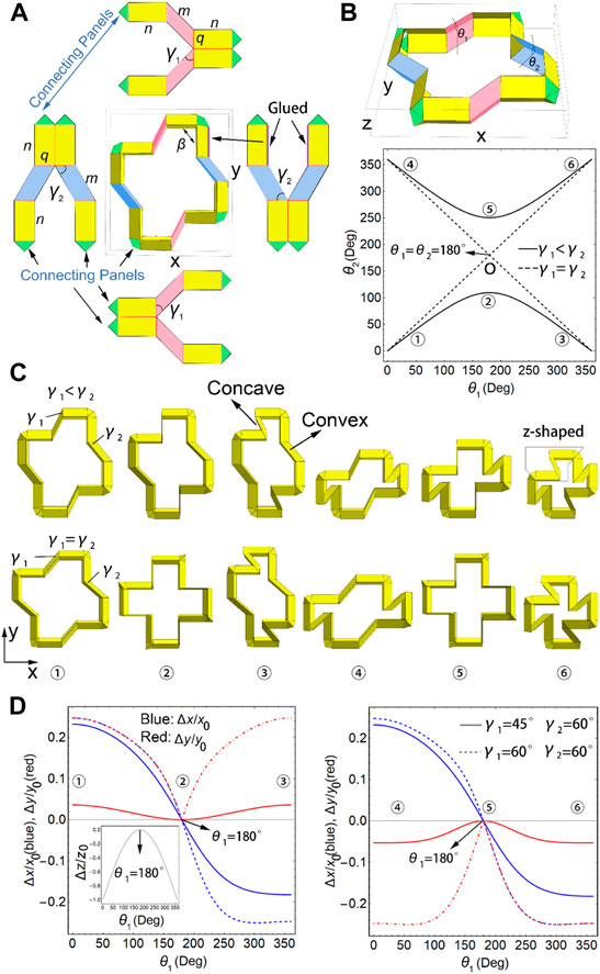
FIGURE 1. Ring-like unit design. (A) Ring-like unit comprising four “z”-shaped structures with their 2D folding patterns and lengths (
The ring-like unit samples were fabricated using the Strathmore 500 Series 3-ply Bristol card stock that was laser cut based on a design pattern generated using Mathematica 11.2. The edges of the given panels were glued to be connected (Figure 1A) to build 3D units for flexible foldability. See SI Section 6 for details.
The calculation methods for the sizes of a ring-like unit and four-unit combination comprising four ring-like units and the design method for targeted Poisson’s ratios are given in SI Sections 1–4.
The top box, camera, and bottom box were connected and moved together with the test head under the control of a universal testing machine. The sample was put on a motionless substrate. When the bottom box touched the sample, it was deformed and captured using a camera. Then, the binary images of the sample at different times were obtained, and the sample in each image was enclosed within a minimum enclosed rectangle, and then, the x- and y-sizes were obtained. Finally, the real size of the sample was obtained by using a conversion factor of 0.4167 mm/pixel. The experimental setup is shown in Figure 3F.
Here, we used Mathematica 11.2 software to simulate the deformation using geometrical relation equations (see SI) to obtain the vertex coordinates and then the facets of the structures at different deformation angles.
Once
Here, the ring-like units possess various deformation behaviors in the x- and y-directions. Figure 1D shows the isotropic deformations for
There are two degrees of freedom (DOFs) of the ring-like unit, that is,
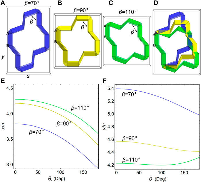
FIGURE 2. Shearing deformation modes of the ring-like unit. Configurations of the ring-like unit with (A)
To demonstrate the analytical geometrical model with experimental data, we compressed a paper-made ring-like unit (Figure 3) in the z-direction using a universal testing machine. Here, the unit with
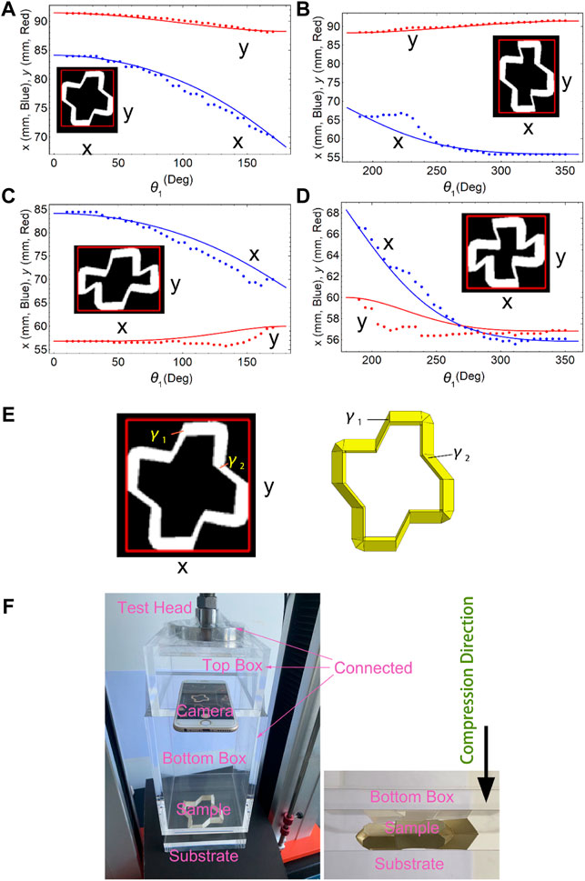
FIGURE 3. Experimental verification. Dimensions of a unit with
After validating the analytical model, we focused on the inverse design of a unit with
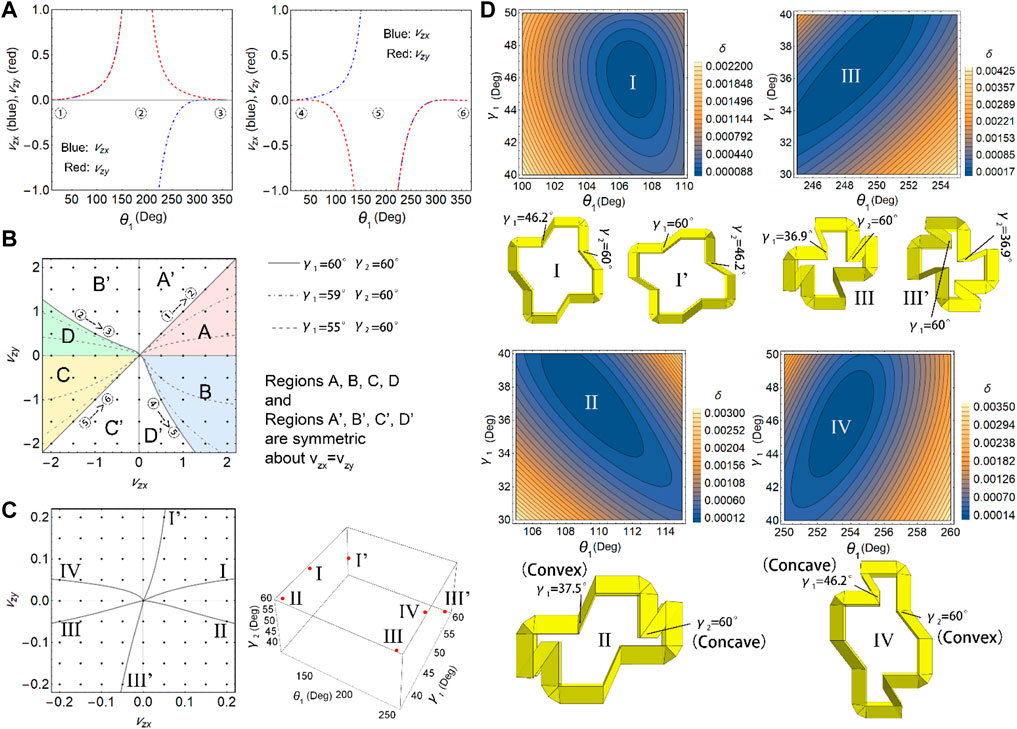
FIGURE 4. Optimal design for the targeted Poisson’s ratios in the x- and y-directions. (A) Poisson’s ratios along different deformation paths with
The optimization of the structures for given Poisson’s ratios in the x- and y-directions can be achieved by minimizing the error,
After understanding the deformation mechanism of one ring-like unit, here we focus on that with multiple units. Four identical ring-like units can be combined to form a four-unit combination, which can be periodically replicated to construct a 2D cellular structure, as shown in Figure 5A (in the gray shade, the four-unit combination is displayed with a yellow–pink–yellow–pink pattern because the diagonal ring-like units are with the same configuration). Although the four ring-like units are identically designed with
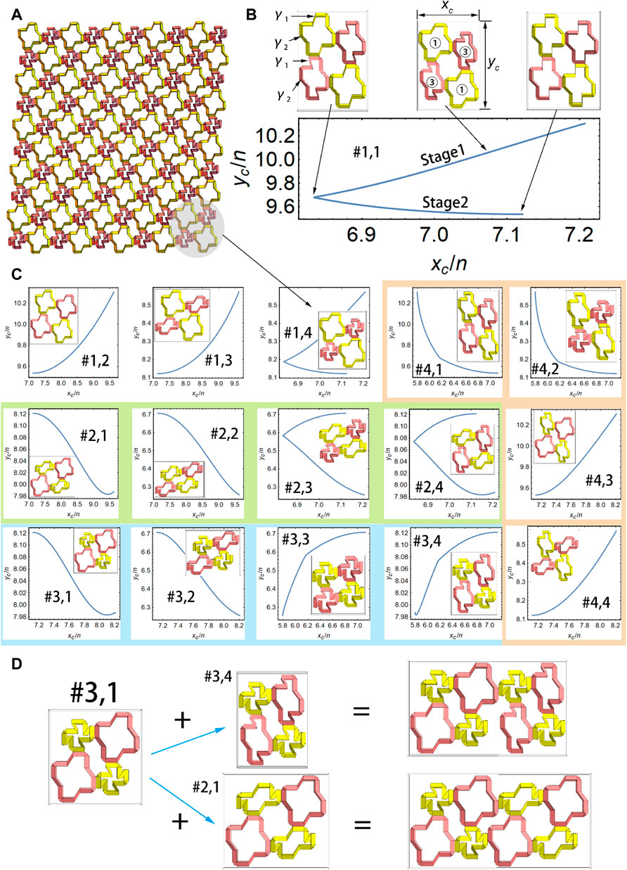
FIGURE 5. Multiple deformation patterns of 2D cellular structures. (A) 2D cellular structures comprising
The shearing deformation of the 2D cellular structures with
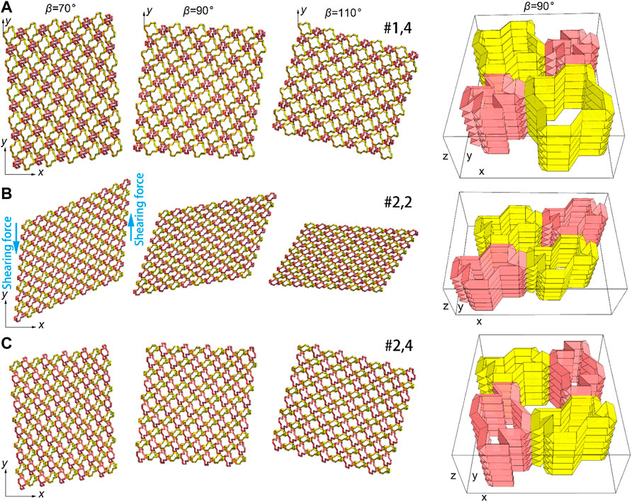
FIGURE 6. Shearing deformation modes of the 2D cellular structure. Three of the 16 discrete patterns in Figure 5C, (A) #1.4 (B) #2.2 (C) #2.4; column 1–3, 2D cellular structures with
Finally, we explore another design of cellular structures consisting of multiple ring-like units with
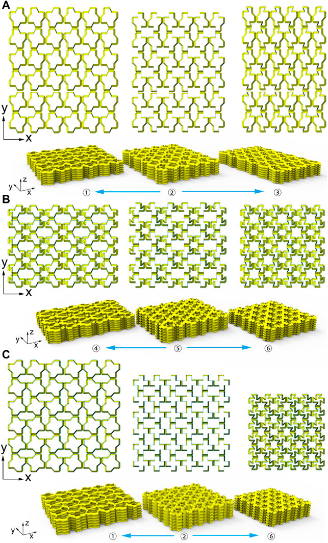
FIGURE 7. Three patterns of 3D cellular structures. (A) Deformation paths
The cellular structures in Figure 7 with 6 × 6 × 6 units look like 2.5D because for each unit, the height is less than the length or the width. But in essence, the structures are 3D since the layers can be continuously stacked along the z-direction, such as with 6 × 6 × 12 units. Here, we used 6 × 6 × 6 units for clear visualization.
We have investigated the unique kinematics of kirigami-based 3D metamaterials with ring-like units. We foundd that the various combinations of Poisson’s ratios (values and signs) can be obtained with different combinations of the design angles
The original contributions presented in the study are included in the article/Supplementary Material; further inquiries can be directed to the corresponding authors.
NY designed and performed the research; JZ and SW processed the data; NY and YY analyzed the data and wrote the manuscript.
This work was supported by the National Natural Science Foundation of China (11872046), the Scientific Research Funding of Shantou University (NTF19012), the 2020 LKSF Cross-Disciplinary Research Projects (2020LKSFG01D), the Natural Science Foundation of Guangdong, China (2021A1515010318, 2022A1515011024, and 2018A030307030), the Key Project of Guangdong Provincial Department of Education (2021ZDZX2007), and the Science and Technology Project of Guangdong, China (180917114960497).
The authors declare that the research was conducted in the absence of any commercial or financial relationships that could be construed as a potential conflict of interest.
All claims expressed in this article are solely those of the authors and do not necessarily represent those of their affiliated organizations, or those of the publisher, the editors, and the reviewers. Any product that may be evaluated in this article, or claim that may be made by its manufacturer, is not guaranteed or endorsed by the publisher.
The Supplementary Material for this article can be found online at: https://www.frontiersin.org/articles/10.3389/fphy.2022.909536/full#supplementary-material
1. Lee K, Wang Y, Zheng C. Twister Hand: Underactuated Robotic Gripper Inspired by Origami Twisted tower. IEEE Trans Robot (2020) 36:488–500. doi:10.1109/tro.2019.2956870
2. Hu W, Lum GZ, Mastrangeli M, Sitti M. Small-scale Soft-Bodied Robot with Multimodal Locomotion. Nature (2018) 554:81–5. doi:10.1038/nature25443
3. Kanik M, Orguc S, Varnavides G, Kim J, Benavides T, Gonzalez D, et al. Strain-programmable Fiber-Based Artificial Muscle. Science (2019) 365:145–50. doi:10.1126/science.aaw2502
4. Wu W, Hu W, Qian G, Liao H, Xu X, Berto F. Mechanical Design and Multifunctional Applications of Chiral Mechanical Metamaterials: a Review. Mater Des (2019) 180:107–950. doi:10.1016/j.matdes.2019.107950
5. Boatti E, Vasios N, Bertoldi K. Origami Metamaterials for Tunable thermal Expansion. Adv Mater (2017) 29:1700360. doi:10.1002/adma.201700360
6. Mirzaali MJ, Pahlavani H, Zadpoor AA. Auxeticity and Stiffness of Random Networks: Lessons for the Rational Design of 3D Printed Mechanical Metamaterials. Appl Phys Lett (2019) 115:021901. doi:10.1063/1.5096590
7. Dudek KK, Gatt R, Dudek MR, Grima JN. Negative and Positive Stiffness in Auxetic Magneto-Mechanical Metamaterials. Proc R Soc A (2018) 474:20180003. doi:10.1098/rspa.2018.0003
8. Yang H, Ma L. Multi-stable Mechanical Metamaterials with Shape-Reconfiguration and Zero Poisson's Ratio. Mater Des (2018) 152:181–90. doi:10.1016/j.matdes.2018.04.064
9. Tan X, Wang B, Zhu S, Chen S, Yao K, Xu P, et al. Novel Multidirectional Negative Stiffness Mechanical Metamaterials. Smart Mater Struct (2019) 29:015037. doi:10.1088/1361-665x/ab47d9
10. Yang N, Chen C-W, Yang J, Silverberg JL. Emergent Reconfigurable Mechanical Metamaterial Tessellations with an Exponentially Large Number of Discrete Configurations. Mater Des (2020) 196:109143. doi:10.1016/j.matdes.2020.109143
11. Dudek KK, Gatt R, Grima JN. 3D Composite Metamaterial with Magnetic Inclusions Exhibiting Negative Stiffness and Auxetic Behaviour. Mater Des (2020) 187:108403. doi:10.1016/j.matdes.2019.108403
12. Sui N, Yan X, Huang TH, Xu J, Yuan FG, Jing Y. A Lightweight yet Sound-Proof Honeycomb Acoustic Metamaterial. Appl Phys Lett (2015) 106:171–905. doi:10.1063/1.4919235
13. Lee C-M, Goverdovskiy VN. A Multi-Stage High-Speed railroad Vibration Isolation System with "negative" Stiffness. J Sound Vibration (2012) 331:914–21. doi:10.1016/j.jsv.2011.09.014
14. Le TD, Ahn KK. Experimental Investigation of a Vibration Isolation System Using Negative Stiffness Structure. Int J Mech Sci (2013) 70:99–112. doi:10.1016/j.ijmecsci.2013.02.009
15. Nagarajaiah S, Pasala DTR, Reinhorn A, Constantinou M, Sirilis AA, Taylor D. Adaptive Negative Stiffness: a New Structural Modification Approach for Seismic protection. Amr (2013) 639-640:54–66. doi:10.4028/www.scientific.net/amr.639-640.54
16. Kuribayashi K, Tsuchiya K, You Z, Tomus D, Umemoto M, Ito T, et al. Self-deployable Origami Stent Grafts as a Biomedical Application of Ni-Rich TiNi Shape Memory alloy Foil. Mater Sci Eng A (2006) 419:131–7. doi:10.1016/j.msea.2005.12.016
17. Imbalzano G, Linforth S, Ngo TD, Lee PVS, Tran P. Blast Resistance of Auxetic and Honeycomb sandwich Panels: Comparisons and Parametric Designs. Compos Structures (2018) 183:242–61. doi:10.1016/j.compstruct.2017.03.018
18. Dudek KK, Wolak W, Gatt R, Grima JN. Impact Resistance of Composite Magnetic Metamaterials. Sci Rep (2019) 9:3963. doi:10.1038/s41598-019-40610-w
19. Zhang L, Feih S, Daynes S, Chang S, Wang MY, Wei J, et al. Energy Absorption Characteristics of Metallic Triply Periodic Minimal Surface Sheet Structures under Compressive Loading. Additive Manufacturing (2018) 23:505–15. doi:10.1016/j.addma.2018.08.007
20. Scarpa F, Yates JR, Ciffo LG, Patsias S. Dynamic Crushing of Auxetic Open-Cell Polyurethane Foam. Proc Inst Mech Eng C: J Mech Eng Sci (2002) 216:1153–6. doi:10.1243/095440602321029382
21. Li M, Shen L, Jing L, Xu S, Zheng B, Lin X, et al. Origami Metawall: Mechanically Controlled Absorption and Deflection of Lightflection of Light. Adv Sci (2019) 6:1901434. doi:10.1002/advs.201901434
22. Wang H, Zhao D, Jin Y, Wang M, Mukhopadhyay T, You Z. Modulation of Multi-Directional Auxeticity in Hybrid Origami Metamaterials. Appl Mater Today (2020) 20:100715. doi:10.1016/j.apmt.2020.100715
23. Reis PM, Jaeger HM, Van Hecke M. Designer Matter: A Perspective. Extreme Mech Lett (2015) 5:25–9. doi:10.1016/j.eml.2015.09.004
24. Fang H, Wang KW, Li S. Asymmetric Energy Barrier and Mechanical Diode Effect from Folding Multi-Stable Stacked-Origami. Extreme Mech Lett (2017) 17:7–15. doi:10.1016/j.eml.2017.09.008
25. He YL, Zhang PW, You Z, Li ZQ, Wang ZH, Shu XF. Programming Mechanical Metamaterials Using Origami Tessellations. Composites Sci Tech (2020) 189:108015. doi:10.1016/j.compscitech.2020.108015
26. Zhai Z, Wang Y, Jiang H. Origami-inspired, On-Demand Deployable and Collapsible Mechanical Metamaterials with Tunable Stiffness. Proc Natl Acad Sci U.S.A (2018) 115:2032–7. doi:10.1073/pnas.1720171115
27. Liu B, Silverberg JL, Evans AA, Santangelo CD, Lang RJ, Hull TC, et al. Topological Kinematics of Origami Metamaterials. Nat Phys (2018) 14:811–5. doi:10.1038/s41567-018-0150-8
28. Zhang J, Karagiozova D, You Z, Chen Y, Lu G. Quasi-static Large Deformation Compressive Behaviour of Origami-Based Metamaterials. Int J Mech Sci (2019) 153-154:194–207. doi:10.1016/j.ijmecsci.2019.01.044
29. Brunck V, Lechenault F, Reid A, Adda-Bedia M. Elastic Theory of Origami-Based Metamaterials. Phys Rev E (2016) 93:033005. doi:10.1103/PhysRevE.93.033005
30. Yang N, Silverberg JL. Decoupling Local Mechanics from Large-Scale Structure in Modular Metamaterials. Proc Natl Acad Sci U.S.A (2017) 114:3590–5. doi:10.1073/pnas.1620714114
31. Yasuda H, Yang J. Reentrant Origami-Based Metamaterials with Negative Poisson's Ratio and Bistability. Phys Rev Lett (2015) 114:185502. doi:10.1103/physrevlett.114.185502
32. Ruzzene M, Scarpa F, Soranna F. Wave Beaming Effects in Two-Dimensional Cellular Structures. Smart Mater Struct (2003) 12:363–72. doi:10.1088/0964-1726/12/3/307
33. Qin G, Qin Z. Negative Poisson's Ratio in Two-Dimensional Honeycomb Structures. Npj Comput Mater (2020) 6:51. doi:10.1038/s41524-020-0313-x
34. Yang N, Zhang M, Zhu R. 3D Kirigami Metamaterials with Coded thermal Expansion Properties. Extreme Mech Lett (2020) 40:100912. doi:10.1016/j.eml.2020.100912
35. Wang H, Zhao D, Jin Y, Wang M, Mukhopadhyay T, You Z. Modulation of Multi-Directional Auxeticity in Hybrid Origami Metamaterials. Appl Mater Today (2020) 20:100715. doi:10.1016/j.apmt.2020.100715
36. Pratapa PP, Liu K, Paulino GH. Geometric Mechanics of Origami Patterns Exhibiting Poisson's Ratio Switch by Breaking Mountain and valley Assignment. Phys Rev Lett (2019) 122:155501. doi:10.1103/physrevlett.122.155501
Keywords: mechanical metamaterials, origami, kirigami, deformation paths, Poisson’s ratio
Citation: Yang N, Zhuang J, Wei S and Yu Y (2022) Continuous and Discrete Deformation Modes of Mechanical Metamaterials With Ring-Like Unit Cells. Front. Phys. 10:909536. doi: 10.3389/fphy.2022.909536
Received: 31 March 2022; Accepted: 26 May 2022;
Published: 04 July 2022.
Edited by:
Yangyang Chen, Hong Kong University of Science and Technology, Hong Kong SAR, ChinaReviewed by:
Zongliang Du, Dalian University of Technology, ChinaCopyright © 2022 Yang, Zhuang, Wei and Yu. This is an open-access article distributed under the terms of the Creative Commons Attribution License (CC BY). The use, distribution or reproduction in other forums is permitted, provided the original author(s) and the copyright owner(s) are credited and that the original publication in this journal is cited, in accordance with accepted academic practice. No use, distribution or reproduction is permitted which does not comply with these terms.
*Correspondence: Nan Yang, bnlhbmdAc3R1LmVkdS5jbg==; Ying Yu, eXV5aW5nQHN0dS5lZHUuY24=
Disclaimer: All claims expressed in this article are solely those of the authors and do not necessarily represent those of their affiliated organizations, or those of the publisher, the editors and the reviewers. Any product that may be evaluated in this article or claim that may be made by its manufacturer is not guaranteed or endorsed by the publisher.
Research integrity at Frontiers

Learn more about the work of our research integrity team to safeguard the quality of each article we publish.