- Key Laboratory for Far-Shore Wind Power Technology of Zhejiang Province, PowerChina Huadong Engineering Corporation Limited, Hangzhou, China
Although pile foundations are usually subjected to both lateral and vertical loads, there have been few studies on the pile response under the combined loadings. Moreover, those few studies led to inconsistent conclusions concerning the influence of vertical load on the lateral pile response. This study aims to investigate the effect of vertical load on the monotonic and cyclic lateral response of piles in normally consolidated (NC) and over-consolidated (OC) clay through a series of centrifuge tests. Three-dimensional finite element analyses using an advanced hypoplastic clay model were also performed to gain deep insight into the mechanism. It is revealed that after applying the vertical load and allowing the dissipation of the induced excess pore pressure, the lateral initial stiffness and ultimate capacity of the pile in the NC clay increased by 10.0 and 49.4%, respectively. However, in the OC clay, the application of the vertical load resulted in a 12.6 and 32.4% reduction in the lateral pile initial stiffness and ultimate capacity, respectively, showing a distinct response from that in the NC clay. The above-mentioned distinct influence of vertical load for piles can be attributed to the different evolutions of stress ratio (q/p’) of the soil around the pile in the NC and OC clay, which determines the soil mobilisable shear strength and consequently the lateral pile responses.
Introduction
Pile foundations are widely used in building and offshore structures to resist the combined action of vertical and lateral loads [1–3]. During the past decades, extensive valuable and interesting studies have been carried out to investigate pile lateral response [4–10] or vertical response [11–14]. However, in all these studies, either the vertical loads or horizontal loads are considered independently, which is a simplification of the realistic combined loading condition. In other words, the current practice assumes that the effect of interaction between the vertical and lateral loads on the pile response can be ignored. This is obviously unsuitable. As pointed out by Achmus and Thieken [15] through finite element modelling, under the combined loading, the consistent mobilization of horizontal soil resistance caused by lateral loads and pile shaft shear stress caused by vertical loads will significantly alter both lateral and vertical pile response. Therefore, quantifying the interaction effects on piles under the combined loads would no doubt lead to a more accurate assessment of pile responses.
By far, it is well acknowledged that the presence of the lateral loading and bending moments will significantly reduce the vertical pile capacity [16]. However, the investigations on the influence of vertical load on the lateral response of piles are still limited and there is no consensus on this issue. Based on experimental and field studies, Jain et al. [17], McNulty [18] and Bartolomey [19] observed an increase in lateral pile capacity due to the presence of vertical load. Similar conclusions were also made by Hussien et al. [20] through a series of three-dimensional finite element analyses. On contrary, Karthigeyan and Rajagopal [21] found that the presence of vertical load will reduce the lateral pile ca-pacity and the reduction depends on vertical load level and pile slenderness ratio. Liang et al. [22] and Zhang et al. [23] also pointed out the detrimental effect of vertical load on lateral pile response based on analytical investigations.
It is worth noting that, in most of the existing studies, the vertical load and the lateral load are applied to the pile at the same time, or the lateral load is imposed immediately after applying the vertical load, which means the dissipation of the excess pore water pressure induced by vertical loading is not considered. However, in fact, after the construction of the pile and the upper structure in clay beds, there is a relatively long resting period for the excess pore pressure induced by the vertical loading to dissipate. This will alter the mechanical properties of the soil around the pile and thus plays an important role in the influence of vertical load on the lateral pile response. But this issue has not been investigated yet. In addition to monotonic lateral loading, piles are frequently subjected to cyclic lateral loading, when they are used to support offshore structures or to support infrastructures. The cyclic lateral response of piles has been extensively investigated. Examples are, among others, Basack and Nimbalkar [24], Nimbalkar and Basack [25] and Basack and Dey [26] provide deep insight into the cyclic lateral response of pile groups and single piles through high-quality and comprehensive experimental and numerical investigations. Hong et al. [27] also carried out a series of centrifuge tests to investigate a cyclically loaded semi-rigid pile. White et al. [28] and McCarron [29] proposed a cyclic model for predicting the pile cyclic response. Basack [30] conducted a comprehensive review and detailed summarized the important observations made by the researchers working in the area of cyclically loaded piles and utilize them to provide a simple-yet-powerful guideline for the recommendation of suitable design methodology. It should be also noted that, most of the studies have not explored the cyclic pile response under the influence of vertical loading.
Given the above discussions, this study aims to understand the influence of the vertical load on the subsequent lateral monotonic and cyclic pile response, considering the dissipation of the excess pore pressure induced by the vertical loading (reconsolidation process). To achieve this goal, a series of centrifuge tests modelling a pile under the combined vertical and lateral loading was carried out in both normally consolidated clay (NC) and over-consolidated clay (OC). In the tests, to meet the in-situ condition, a vertical load is firstly applied and a resting period is intervened for the dissipation of the excess pore pressure. After that, a monotonic or multi-stage cyclic lateral load is imposed and the resulting pile responses are examined to illustrate the influence of the vertical load on the subsequent lateral pile response. In addition to the centrifuge tests, three-dimensional finite element analyses using an advanced hypoplastic clay model were also performed to provide further insights into this issue.
Centrifuge Modelling
The basic premise in centrifuge modelling is that a 1/N (N is the gravitational acceleration in the centrifuge) scale model of a prototype is tested in the enhanced gravity field of a geotechnical centrifuge. The gravity is increased by the same geometric factor N relative to the normal earth’s gravity field (referred to as 1 g). Scaling factors are relationships that relate the behaviour of the centrifuge model and the prototype. The stresses and strains are identical in the centrifuge model and the prototype (Taylor [31]). Based on this, the scaling factors of other parameters can be readily derived, as summarized in Table 1 (Taylor [31]).
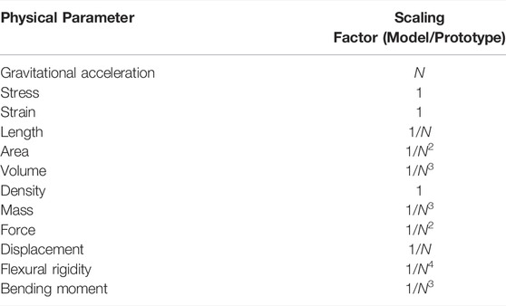
TABLE 1. Scaling factors relevant to centrifuge tests in this study (Taylor [31]).
All the centrifuge model tests were performed at a centrifugal acceleration of 40 g at the geotechnical centrifuge facility of the Hong Kong University of Science and Technology. The centrifuge has an arm radius of 4.2 m and can operate at up to 150 g with a maximum payload of 400 g t. Details on the centrifuge can be found in Ng et al. [32].
Test Program
A total of eight centrifuge tests were conducted modelling the monotonic and cyclic lateral response of a pile with and without the application of vertical load in NC and OC clay. The test program and objectives are summarized in Table 2. The lateral response of the pile in the NC and OC clay under the pure monotonic and cyclic load was first evaluated. Then, the response of piles to combined vertical and lateral loads was investigated for the value of the vertical load equals 50% of the ultimate vertical load capacity Vult. In this study, the Vult of the pile was estimated based on the API guideline [33]. The combined loads were applied in two stages. In the first stage, the vertical load was applied by dead weight (see section 2.2) and a reconsolidation stage was intervened for the fully-dissipation of the excess pore pressure induced by the previous vertical loading. In the second stage, a monotonic or cyclic lateral load was applied while keeping the vertical load constant.
In the monotonic tests (Test 1–4), the pile was pushed laterally by a large displacement to obtain the ultimate lateral pile capacity. A rate of loading displacement of 1 mm/s was adopted to ensure undrained conditions [34]. It is worth noting that, a servo-controlled loading system was adopted in the centrifuge tests. The actuator rod was set to contact the pile before the tests. A displacement transducer (LVDT) was attached to the actuator rod to provide feedback to the closed-loop system. In the monotonic tests, displacement-controlled loading was applied to the pile based on the feedback of the attached LVDT, which determines the stroke and the movement rate of the actuator. Therefore, the pile displacement and the rate of the displacement can also be well controlled. More details about the servo-controlled loading system can be found in Kirkwood [35]. In the tests that include cyclic loading (Test 5–8), a series of successive episodes of cycling were imposed on the pile. 100 cycles were involved in each cycling. The cyclic amplitude of each episode of cycling was continuously increased and the cycles were continued until the accumulated lateral pile dis-placement exceeded 1.2D. In this study, approximately one-way cycling was considered. In practice, a pile is to be cyclically loaded with a frequency ranging between 0.01 and 1 Hz. According to the scaling law for frequency, which is, 1: N (see Taylor [31], where N means the centrifugal acceleration is N times of the gravitational acceleration), the frequency of input cyclic load in the centrifuge test would fall into the range between 1 and 100 Hz in model scale. To avoid any inertial effects caused by high-frequency loading, the lower bound of the frequency range, i.e., 1 Hz, was adopted in this study and also elsewhere [4, 6].
Model Pile and the Application of Vertical Load
The model pile used in this study was made of a 420 mm (17.2 m in prototype) long aluminum pipe with a diameter D and a wall thickness t of 19 mm (0.8 m in prototype) and 1 mm (0.023 m in prototype), respectively. The type of the aluminum alloy is 6061-T651, which has an ultimate yield strength of 228 MPa and an elastic modulus of 72 GPa. The embedded pile length L was 330 mm (13.2 m in prototype), leading to the length-to-diameter ratio (L/D) equal to 16.5. As proposed by Polous and Hull [36], the relative pile-soil stiffness can be expressed as EpIp/EsL4, where EpIp and Es are the pile flexural rigidity and soil modulus, respectively. The Es of the soil used in this study (to be presented in the next section) is equal to about 400 times its undrained shear strength [27]. The calculated values of the dimensional parameter EpIp/EsL4 of the pile in the reported NC and OC clay are in the range of the upper bound for a flexible pile (0.0025) and the lower bound (0.208) for a rigid pile. Therefore, the model pile tends to behave as a semi-rigid pile.
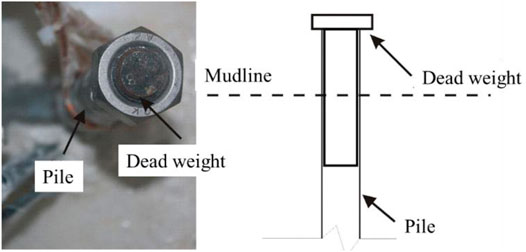
For the combined loading tests, the vertical load was applied in the form of deadweight (represented by mass block) at the pile head, as shown in Figure 1. The mass block was manufactured as a strip steel rod, which can be directly embedded in the pile head and fit closely with the inner side of the pile. In addition, the position of the center of gravity of the mass block was designed to be at the mudline to avoid posing any additional bending moment caused by the vertical load during the lateral pile movement. The weight of the mass was carefully controlled to meet the target value of the vertical load, i.e., 50%Vult, which was 77 and 240 kN (in prototype) for piles in the NC and OC clay, respectively. After the installation of the mass block, high-strength glue was filled to the small gaps between the pile and the mass block to connect the two parts.
Model Soil and Undrained Shear Strength Profile
The soil adopted in the centrifuge tests was Speciwhite China kaolin clay. The index properties and geotechnical parameters of the clay have been well investigated [37]. Two model boxes of soil sample for making the NC and OC clay bed was prepared in this study. Firstly, a 50 mm (2 m in prototype) thick sandy layer was sprinkled into the bottom of the model boxes to provide for drainage beneath the kaolin clay. The inner surface of the model boxes was then coated with silicone grease to minimize the friction against the soil. Kaolin clay powder was mixed at an initial water content of 120% (twice the liquid limit) with de-ionized water. The method of preparation of the clay layer strictly followed the standard specification of BS 1377 (BSI [38]), which has been widely adopted in centrifuge tests for preparing soil bed. The mixing process was conducted under vacuum for about 6 h. The fully saturated slurry was then carefully transformed to the model boxes. One-dimensional consolidation at 1 g was carried out first, by applying deadweight on the top of the soil surface. The maximum surcharge loading of 20 and 250 kPa was applied for preparing the NC and OC clay bed, respectively.
After 1 g consolidation, the surcharge was removed and the model box was put into the centrifuge and spun up to 40 g for self-weight consolidation. The degree of consolidation was determined using the method proposed by Tan et al. [39] based on the consolidation settlements measured by vertical LVDTs. The target degree of consolidation of each soil bed was 90%, which is likely to signify the completion of primary consolidation. At 40 g, the distribution of the over-consolidation ratio (OCR) of the clay beds can be readily deduced, as shown in Figure 2A. For the NC clay bed, only the soil at shallow depth (0–3.5 m below the mudline) was over-consolidated due to previous maximum overburden stress, i.e., 20 kPa at 1 g consolidation. For the OC clay bed, the OCR decreases with soil depth with the value of 2.9 at the depth of the pile tip.
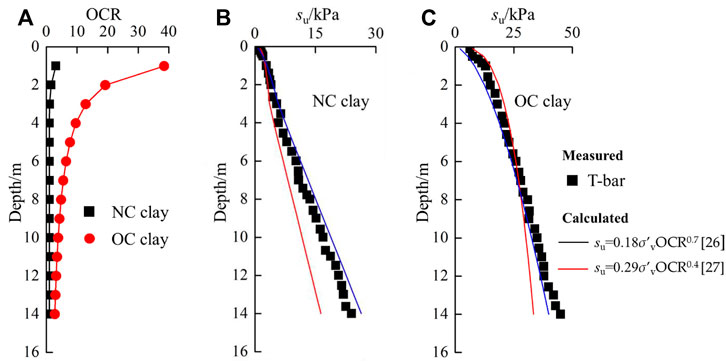
FIGURE 2. Distribution of (A) Over-consolidated ratio; (B) Undrained shear strength of the NC clay; (C) Undrained shear strength of the OC clay.
Once the soil consolidation is completed, the undrained shear strength profile of the soil samples was then assessed by a T-bar penetrometer (with a bar diameter of 6.5 mm and a length of 35 mm in model scale) at 40 g. In this study, a penetration rate of 3 mm/s was adopted to ensure under undrained conditions [34]. Figures 2B,C show the profile of undrained shear strength (su) of the NC and OC clay bed, respectively, by using a constant T-bar factor of Nkt = 10.5 [40]. As indicated, the su profile of the NC and OC clay increases linearly and exponentially with depth, respectively. Calculated strength profiles according to the two empirical equations proposed by Bolton and Stewart [41] and Gourvenec et al. [42] are also included for comparison.
Experimental Setup
Figure 3 shows the elevation view of the centrifuge model package. The model box has a plane area of 1,245 mm × 300 mm (49.8 m × 12 m in prototype) and a depth of 850 mm (34 m in prototype). There were two strata of the soil models, i.e., a 550 mm thick (22 m in prototype) kaolin layer and a 50 mm thick (2 m in prototype) bottom sandy layer. The horizontal spacing between the outer boundary of the pile and the wall of the model box was design to be more than 7.5D, thus the boundary effect can be ignored [43]. A servo-controlled loading system was mounted on a rigid reaction beam, the direction and the location of the loading system can be adjusted to fit all the pile tests. A load cell and a linear variable differential transformer (LVDT) were attached to the actuator rod to measure the lateral load and displacement at the loading height, respectively. A loading height of 50 mm (2 m in prototype) was adopted in each pile test.
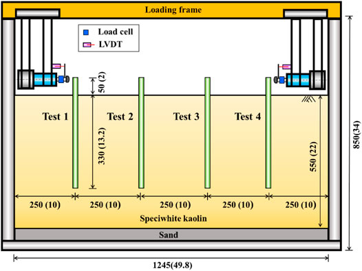
FIGURE 3. Typical elevation view of the centrifuge model package for test 1-4. Note: All dimensions are in millimeters except for numbers in parentheses, which denote prototype scale (unit: m).
Centrifuge Test Results
In the following sections, all results are presented in prototype scale, unless stated otherwise.
Influence of Vertical Load on Monotonic Lateral Pile Response
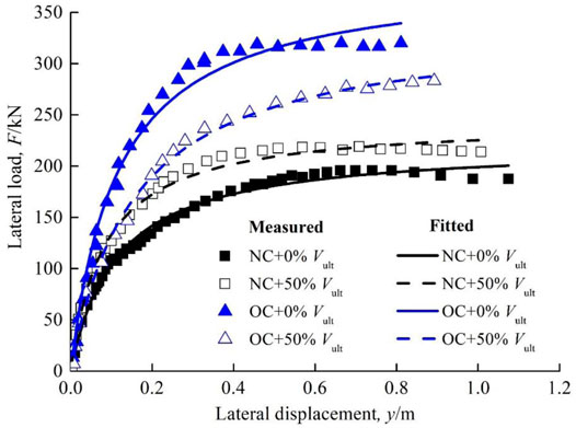
Figure 4 shows the measured lateral load-displacement response at the loading point. It can be found that, in the NC clay, the lateral pile response including the initial stiffness and the ultimate capacity was enhanced after applying the vertical load and allowing the dissipation of the induced excess pore pressure. This indicates the application of the vertical load may play a positive role for piles in NC clay in resisting lateral loads. On the contrary, in the OC clay, as can be seen in the figure, the presence of the vertical load led to a reduction in the initial stiffness and the ultimate capacity of the pile, showing a detrimental effect.
To further quantify the influence of vertical load on lateral pile response, a hyperbolic curve (see Equation 1) recommended by Kulhawy and Chen [44] was adopted in this study to fit the measured relationships between the lateral load (F) and the resulting lateral displacement (y). This method has been widely used for determining initial stiffness k and ultimate capacity Fu of piles [5, 27, 45].
Where m and n are two fitting parameters. The k and Fu can be interpreted from the reciprocals of m and n, respectively.
The fitting results are also plotted in Figure 4, which exhibit an excellent match with the measured data. The values of k and Fu of the pile in each test are deduced based on the above-mentioned method, as summarized in Table 3. It can be found that, in the NC clay, the ultimate capacity and the initial stiffness of the pile have increased by 10 and 49.4%, respectively, due to the application of the vertical load. Conversely, in the OC clay, the presence of the vertical loading results in a 12.6 and 32.4% reduction in the ultimate capacity and the initial stiffness of the pile. This phenomenon demonstrates that the application of the vertical load will lead to either beneficial or detrimental effects on the lateral pile response, depending on the clay conditions, i.e., normally consolidated or over-consolidated. The mechanism will be further investigated through finite element analysis, as presented in section 4.
Influence of Vertical Load on Cyclic Lateral Pile Response
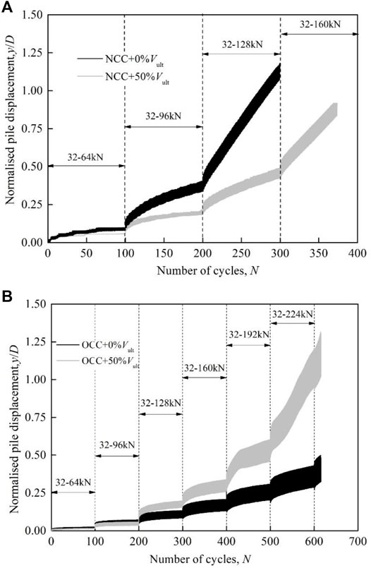
Figures 5A,B show the measured cumulative displacement of the pile during the cyclic tests in the NC and OC clay, respectively. As anticipated, the lateral pile displacement accumulates with the number of cycles and cyclic loading amplitudes in each condition. The influence of the vertical load on the cyclic lateral pile response is consistent with that on the monotonic pile response.
As presented in Figure 5A, in the NC clay, at any given loading amplitude, the pile displacement is remarkably reduced (up to 45%) when the vertical load is applied at the pile head and the dissipation of the induced excess pore pressure is allowed. It can be also found that the reduction in pile cumulative displacement increases with the increase in cyclic loading amplitude. This is because when the cyclic loading increases, the response of the pile subjected to the pure lateral load in the NC clay tends to transform from a shakedown pattern (i.e., displacement increases with a decreased rate) to a ratcheting pattern (i.e., displacement increases linearly with number of cycles). However, for the pile subjected to the combined loadings, the enhancement in pile lateral stiffness and ultimate capacity caused by the vertical load (see Section 3.1) will slow this transformation process, leading to a more significant difference in cumulative displacement between the conditions with and without the vertical load.
Differing from the beneficial effect observed in the NC clay, the presence of the vertical loading results in a larger cumulative pile displacement in the OC clay, exhibiting a detrimental effect, as shown in Figure 5B. This implies that ignoring the influence of vertical load will underestimate the accumulated displacement of piles in OC clay, leading to a non-conservative pile design that poses a risk to the supported structures.
Three-Dimensional Finite Element Modelling
Through the centrifuge tests (Section 3), the distinct influence of vertical load in lateral response of the pile in the NC and OC clay has been revealed. However, the mechanism behind this phenomenon is still unclear. Therefore, this section reported an additional numerical study using an advanced hypoplastic clay model to gain deep insight into the mechanism of the influence of vertical load in lateral pile response.
Finite Element Mesh
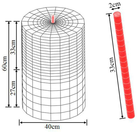
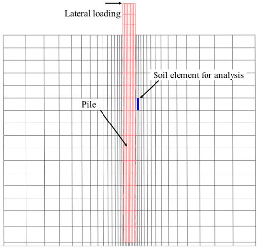
The numerical analyses were performed using the finite element software ABAQUS. Figure 6 shows the isometric view of the finite element mesh of the numerical back-analysis for the monotonic centrifuge tests. Dimensions of the pile and soil were identical to those adopted in the centrifuge model tests. Each lateral boundary and the bottom boundary of the finite element mesh is constrained by roller and pinned supports, respectively. A gravitational acceleration of 40 g was imposed on the entire mesh to model the test condition.
The clay and the pile were modeled using Eight-node brick with pore pressure (C3D8P) and Eight-node brick (C3D8) elements, respectively. The pile was assumed to be linear elastic. An advanced hypoplastic clay model (see the following subsection) was adopted for the numerical study. The interaction between the pile and the soil was simulated based on the Coulomb friction law and the frictional coefficient of μ = 0.31 was adopted following the equation proposed by Randolph and Wroth [46]. The suitability of the mesh density is justified by halving the current size of the mesh and running one more analysis. The computed load-displacement response of the pile under pure lateral loading with the two mesh sizes differs by no more than 5%, confirming the validity of the mesh size adopted in the present study.
Advanced Hypoplastic Clay Model and Model Parameters
A hypoplastic clay model [47] with small stiffness was selected in this study to represent the advanced soil constitutive model. The hypoplastic clay model can predict the non-linear soil behavior, with high stiffness at very small strains and a non-linear decrease of stiffness with increasing strain level. The general form is expressed as follows:
Where T and D represent the objective stress rate and the Euler stretching tensor, respectively. L and N are fourth- and second-order constitutive tensors; fs and fd are two scalar factors.
To incorporate the small-strain stiffness of clay, the so-called intergranular strain concept is combined in the model [48]. The intergranular strain δ is introduced as a new tensorial state variable and the normalized form is:
Where R is a model parameter that represents the size of the elastic range. The direction of δ can be expressed as:
After introducing the intergranular strain, the general form can be rewritten as:
Where χ controls the rate of stiffness degradation; mrat denotes the ratio between initial small-strain stiffness upon a 90°strain path reversal and the initial stiffness upon a 180°strain reversal; mR denotes the initial small-strain stiffness upon a 180°strain path reversal, which can be calibrated based on the initial stiffness G0 [49]:
Where Ag and ng are two model parameters; pr is a reference pressure equals to 1 kPa.
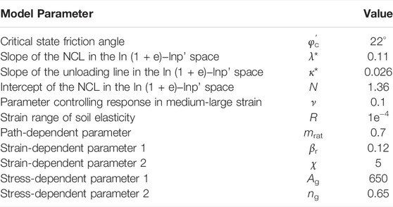
In summary, the hypoplastic clay model used in this study consists of 11 parameters. The basic model requires five parameters φc, N,λ*,κ* and ν. These parameters have the similar physical meaning as the parameters of the Modified Cam clay model. Apart from the five parameters controlling the monotonic behavior of clay at medium to large strain levels, there are six other parameters governing the small-strain stiffness of clay subjected to various path reversals, i.e., R, mrat, βr, χ, Ag and ng.
Table 4 summarizes the model parameters adopted in this study. The basic model parameters of the kaolin clay used in this study, i.e., φc, N,λ* and κ* were obtained from He [50] and Al-Tabbaa [37]. The values of the parameters R, mrat, βr and χ were calibrated by He [36] against data reported by Benz [51] on the small-strain stiffness of kaolin clay. The other three parameters ν, Ag and ng were calibrated against data of cyclic triaxial test carried by Hong et al. [27].
Model Validation
In the numerical analysis, concentrated vertical loads identical to that in centrifuge tests were applied to the center of the pile at the mudline. A consolidation step was set for dissipating the excess pore pressure induced by the vertical loads. After the dissipation, the pile was then laterally pushed to failure. It is worth noting that the numerical analyses performed herein aim to reveal the mechanism of the influence of vertical load to lateral pile analyses but do not intend to reproduce all the centrifuge test results. Therefore, only the monotonic centrifuge tests (Test 1–4) were modelled in the numerical analysis. Figure 7 shows the comparison between the measured and computed monotonic load-displacement response of the pile in both NC and OC clay. It can be found that the numerical analysis has well reproduced the vertical loading caused a beneficial effect in the NC clay and the detrimental effect in the OC clay. The good match between the measured and computed results demonstrates the capability of the numerical model.
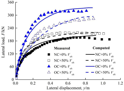
FIGURE 7. Comparison between the measured and computed monotonic load-displacement relationships of the pile.
To further validate the developed numerical model, the centrifuge tests on two laterally loaded large-diameter long monopiles in kaolin clay reported by Lai et al. [5] were simulated based on the developed numerical model with the same model parameters (see Table 4), and the measured and computed results are compared. In their tests, the two piles have an identical embedded depth (L = 60 m in prototype) but different diameters (D = 4 and 6 m in prototype), leading to L/D ratios of 10 and 15. The model pile was made of type ‘7075-T6’ aluminium alloy pipe (Young’s modulus = 72 GPa) with a thickness of 2 mm (t = 0.2 m in prototype). The lateral load was applied to the piles at an eccentricity of 8 m in prototype. More details are given in Lai et al [5]. Figure 8 shows the comparison between the measured and computed load-displacement response of the piles. It can be seen that the computed load-displacement relations using the developed numerical model show satisfactory agreements with the measured data of both piles, demonstrating the predictive capability of the developed numerical model. The above model validations providing reliable evidence for further investigations, as presented in the following section.
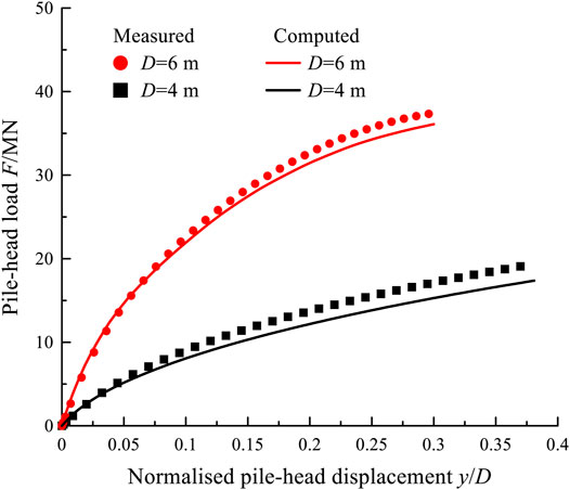
FIGURE 8. Model validation against centrifuge test performed by Lai et al. [5].
Mechanism of the Influence of Vertical Load in Lateral Pile Response
To reveal the mechanism of the influence of vertical load in lateral pile response, the stress path of a typical soil element in the front of the pile (as shown in Figure 9) was extracted for analysis.
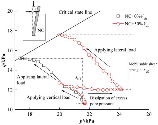
Figure 10 shows the extracted stress paths of the soil element during the whole testing process in the NC clay. In the figure, q and p’ denote shear stress and mean effective stress. It can be seen that, for the piles subjected to the pure lateral loading (i.e., without the vertical loading), the stress ratio (q/p’) of the soil element continuously increases due to the shearing during the loading process and finally reaches the soil critical state line, indicating soil failure. However, when the vertical load is applied to the pile and allows the dissipation of the induced excess pore pressure, the stress path of the soil element can be basically divided into three stages (as shown in Figure 10): 1) During the action of the vertical loading, the stress path moves left (q/p’ increases) due to the undrained shear caused by the vertical loading; 2) During the consolidation period, the excess pore pressure induced by the previous vertical loading dissipates, causing the stress path moves right decreases (q/p’ decreases) and finally tends to be stabilized (reflecting the fully-dissipation); 3) After the consolidation, the lateral load is applied to the pile, forcing the stress path of the soil element moves left to reach the critical state line. Based on the critical state soil mechanics (Muir Wood [52]), soil moblisable shear strength is represented by the difference in shear stress q between the current soil state and the failure state (i.e., the soil state reaches the critical state line). It can be found from the figure that, due to the different evolution of the stress path, the soil mobilisable shear strength during the lateral loading in the case with the vertical load (su2, as shown in the figure) is approximately 20% higher than that in the case without the vertical load (su1, as shown in the figure). The increase in the soil mobilisable shear strength consequently leads to an enhancement in lateral initial stiffness and ultimate capacity of the pile.
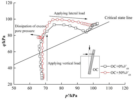
Figure 11 depicts the extracted stress path of the soil element in the OC clay. For the case without the vertical load, a typical stress path of over-consolidated soil under undrained shearing is observed. While, for the case with the vertical loading, three stages of the stress path can also be identified: 1) During the vertical loading, the stress path almost goes vertically (q/p’ increases) and a small amount of negative excess pore pressure is induced since the soil is over-consolidated; 2) In the subsequent consolidation stage, the dissipation of the small amount of the excess has minor influence on the stress path; 3) During the lateral loading, the stress path moves left (q/p’ decreases) and finally reaches the failure state. The comparison between the stress paths in the figure indicates the presence of the vertical load will decrease the mobilisable shear strength of the soil around the pile in the OC clay, resulting in a detrimental effect on resisting lateral loads, as shown in Figures 4, 5.
Design Recommendations
The main contribution of this study is to reveal the opposite effect caused by vertical load on lateral responses of piles in NC and OC clay. It is found that after applying the vertical load and allowing the dissipation of the induced excess pore pressure, the lateral initial stiffness and ultimate capacity of the pile in the NC clay will increase. However, in the OC clay, the application of the vertical load resultes in a reduction in the lateral pile initial stiffness and ultimate capacity. Therefore, before the design of laterally loaded piles, the vertical forces caused by the upper structures and other resources should be carefully assessed, and a detailed site-investigation is recommended to judge the soil condition (whether it is normally consolidated or over-consolidated).
In addition, it should be noted that, in NC clay, the increase in ultimate lateral capacity of piles caused by the application of vertical load is absolutely beneficial to the supported structures, however, the accompanied enhancement in pile initial stiffness may lead to adverse effects on the supported structures. For example, piles with large diameters have been widely used for supporting offshore wind turbines. To avoid any resonance and ultimately increased fatigue damage, the initial natural frequency of the pile-supported turbine structure should lie outside the so-called ‘1P’ and ‘3P’ bands. 1P is defined as the first order natural frequency of the turbine rotor. It is worth noting that 1P is not a single frequency but a range of frequency associated with the lowest and the highest rotational speed of the rotor. 3P is related to the dynamic load triggered when either of the three blades of a wind turbine passes the tower of the turbine structure. Once each of the blades passes the tower, it obscures the shielded area of the tower (by the presence of the passing blade) from the action of wind load, resulting in a dynamic load having frequency equal to three times the rotor frequency (3P) for three-bladed wind turbines (Arany et al. [53]). Typical 1P and 3P bands are presented in Figure 12 [54].
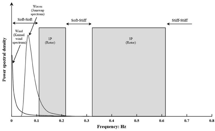
FIGURE 12. Typical 1P and 3P bands of an offshore wind turbine (Jonkman et al. [54]).
It can be seen, to avoid any resonance, the natural frequency of the system should be designed to be lower than 1P (i.e., ‘soft–soft’), between 1P and 3P (i.e., ‘soft–stiff’) or larger than 3P (i.e., ‘stiff–stiff’ regions). Typically, the initial natural frequency of most offshore wind turbines is designed to be ‘soft–stiff’ (in the narrow range between the 1P and 3P frequency) accounting for the cost and design feasibility [53]. Based on the conclusion reported herein, in NC clay, the application of vertical load will increase pile capacity, on the other hand, it will also enhance the pile initial stiffness, which will amplify the natural frequency, forcing it to unfavorably approach the 3P frequency limit that could trigger resonance. Therefore, the influence of vertical load is strongly recommended to be well treated and evaluated even in NC clay (despite bringing beneficial effect on pile capacity) to ensure the reliability of the offshore wind turbine structures.
It should be noted that the quantitative influences of vertical loading on pile lateral response were derived based on the centrifuge tests reported in this study, and may be specific to the particular test conditions and soil type adopted. Thus, the quantitative influences made in this study only provide practical references for similar conditions, any extrapolation of the quantitative influences should be treated with caution. By far, there is no well-established and well-acknowledged method for predicting the influences of vertical loading on pile lateral response, therefore, in the design practice, it is recommended to perform the site-specific three-dimensional finite element analysis (like the numerical model reported herein) to quantify the influences of vertical loading.
Limitations
It should be noted, in this study, only a fixed cyclic loading frequency and pile fixity condition (i.e., free head) are considered in this study. This is absolutely a limitation. Basack and Nimbalkar [24] carried out extensive high-quality laboratory model tests and numerical analyses to investigate the cyclic lateral response of pile groups in soft clay with variations in the loading frequency, loading amplitude and number of cycles. It is revealed that when the loading frequency increases, the degradation factor in lateral pile capacity will increase (can be up to 25%) with a descending rate. In addition to the fixed loading frequency, in this study, only free-head piles are modelled. However, in practice, pile heads are not completely free since a limited rotational and translational restraint are evident in most cases, such as the monopiles used for supporting offshore wind turbines. As pointed out by Randolph and Gourvernec [55], the pile head fixity condition will significantly alert the pile failure mechanism and thus consequently influence the pile capacity and stiffness. Given the above discussions, loading frequency and pile head fixity condition play important roles in lateral pile responses. Investigating these influences will be our future pursuit.
Conclusion
This study carried out a series of centrifuge tests to investigate the influence of vertical load on the monotonic and cyclic lateral response of piles in both NC and OC clay. Additional three-dimensional finite element analyses using an advanced hypoplastic clay model were also performed to gain insight into the mechanism of the influence of vertical load. Based on the centrifuge and numerical investigation, it is found that, in the NC clay, when the vertical load (50% Vult) is applied to the pile and allows the dissipation of the induced excess pore pressure, the lateral ultimate capacity and initial stiffness of the pile are increased by 10.0 and 49.4%, respectively, showing a beneficial effect for piles on resisting lateral loading. Due to the beneficial effect, the cumulative pile displacement can be reduced by up to 45% during cyclic loading. Conversely, in the OC clay, the presence of the vertical load will lead to a 12.6 and 32.4% reduction in the lateral ultimate capacity and initial stiffness of the pile, respectively, indicating a detrimental effect, which consequently increases the cumulative pile displacement under cycling. The reason can be attributed to that, in the NC clay, after applying the vertical load and allowing the dissipation of the excess pore pressure, the stress ratio of the soil around the pile right before the lateral loading decreases, causing an increase in the soil mobilisable shear strength for resisting the subsequent lateral load, which consequently leads to the beneficial effect on the pile response. On the contrary, in the OC clay, the q/p’ of the soil around the pile prior to the lateral loading increases, resulting in a decrease in the soil mobilisable shear strength, which plays a detrimental role in resisting the subsequent lateral loads.
Data Availability Statement
The original contributions presented in the study are included in the article/Supplementary Material, further inquiries can be directed to the corresponding author.
Author Contributions
Conceptualization, Methodology, Validation, Writing-original draft preparation, TL and NL. Formal analysis, Investigation, Writing-review and Editing, YL and BH. All authors have read and agreed to the published version of the manuscript.
Funding
This research was funded by National Natural Science Foundation of China, grant number 51909249.
Conflict of Interest
Authors TL, YL, BH, and NL were employed by PowerChina Huadong Engineering Corporation Limited. The authors declare that the research was conducted in the absence of any commercial or financial relationships that could be construed as a potential conflict of interest.
Publisher’s Note
All claims expressed in this article are solely those of the authors and do not necessarily represent those of their affiliated organizations, or those of the publisher, the editors and the reviewers. Any product that may be evaluated in this article, or claim that may be made by its manufacturer, is not guaranteed or endorsed by the publisher.
References
1. Fattah MY, Karim HH, Al-Recaby MKM. Vertical and Horizontal Displacement of Model Piles in Dry Soil with Horizontal Excitation. Proc Inst Civil Engineers-Structures Buildings (2021)174(4):239–58. doi:10.1680/jstbu.18.00207
2. Al-Shakarchi YJ, Fattah MY, Kashat IK. Batter Pile under Inclined Compressive Load. J Eng Colg Eng (2003) 8:289–301.
3. Fattah MY, Al-Soudani WHS, Omar M. Estimation of Bearing Capacity of Open-Ended Model Piles in Sand. Arab J Geosci (2016) 9:1–14. doi:10.1007/s12517-015-2194-8
4. Lai Y, Wang L, Hong Y, He B. Centrifuge Modeling of the Cyclic Lateral Behavior of Large-Diameter Monopiles in Soft clay: Effects of Episodic Cycling and Reconsolidation. Ocean Eng (2020) 200:107048. doi:10.1016/j.oceaneng.2020.107048
5. Lai Y, Wang L, Zhang Y, Hong Y. Site-specific Soil Reaction Model for Monopiles in Soft clay Based on Laboratory Element Stress-Strain Curves. Ocean Eng (2021) 220:108437. doi:10.1016/j.oceaneng.2020.108437
6. Jeanjean P. Re-assessment of P-Y Curves for Soft Clays from Centrifuge Testing and Finite Element Modeling. In: Offshore Technology Conference; 04 May 2009; Houston Texas. (2009)doi:10.4043/20158-ms
7. Byrne BW, McAdam RA, Burd HJ, Beuckelaers WJAP, Gavin KG, Houlsby GT, et al. Monotonic Laterally Loaded Pile Testing in a Stiff Glacial clay till at Cowden. Géotechnique (2020) 70:970–85. doi:10.1680/jgeot.18.pisa.003
8. Doherty P, Gavin K. Shaft Capacity of Open-Ended Piles in clay. J Geotech Geoenviron Eng (2011) 137:1090–102. doi:10.1061/(asce)gt.1943-5606.0000528
9. Nicola AD, Randolph MF. Centrifuge Modelling of Pipe Piles in Sand under Axial Loads. Géotechnique (1999) 49:295–318. doi:10.1680/geot.1999.49.3.295
10. Randolph MF. Science and Empiricism in Pile Foundation Design. Géotechnique (2003) 53:847–75. doi:10.1680/geot.53.10.847.37518
11. Fattah MY, Mustafa FS. Development of Excess Pore Water Pressure Around Piles Excited by Pure Vertical Vibration. Int J Civ Eng (2016) 15:907–20. doi:10.1007/s40999-016-0073-7
12. Al-Shakarchi YJ, Fattah MY, Kashat IK. The Behaviour of Batter Piles under Uplift Loads. In: International Conference on Geotechnical Engineering; October 3-6, 2004; Sharjah, UAE. University of Sharjah (2004).
13. Fattah MY, Zabar BS, Mustafa FS. Effect of Saturation on Response of a Single Pile Embedded in Saturated sandy Soil to Vertical Vibration. Eur J Environ Civil Eng (2017) 24:381–400. doi:10.1080/19648189.2017.1391126
14. Lehane BM, Jardine RJ. Displacement Pile Behaviour in Glacial clay. Can Geotech J (1994) 31:79–90. doi:10.1139/t94-009
15. Achmus M, Thieken K. On the Behavior of Piles in Non-cohesive Soil under Combined Horizontal and Vertical Loading. Acta Geotech. (2010) 5:199–210. doi:10.1007/s11440-010-0124-1
16. Anagnostopoulos C, Georgiadis M. Interaction of Axial and Lateral Pile Responses. J Geotechnical Eng (1993) 119:793–8. doi:10.1061/(asce)0733-9410(1993)119:4(793)
17. Jain NK, Ranjan G, Ramasamy G. Effect of Vertical Load on Flexural Behaviour of Piles. Geotech Eng (1987) 18:185–204.
19. Bartolomey AA Experimental Analysis of Pile Groups under Lateral Loads. In: Proceedings of the Special Session 10 of the Ninth Int. Conf. on Soil Mech. and Foundation Engineering. Tokyo. (1977). p. 187–8.
20. Hussien MN, Tobita T, Iai S, Karray M. On the Influence of Vertical Loads on the Lateral Response of Pile Foundation. Comput Geotechnics (2014) 55:392–403. doi:10.1016/j.compgeo.2013.09.022
21. Karthigeyan S, Rajagopal K. Numerical Investigation of the Effect of Vertical Load on the Lateral Response of Piles. J Geotech Geoenviron Eng (2006) 133:512–21.
22. Liang F, Zhang H, Wang J. Variational Solution for the Effect of Vertical Load on the Lateral Response of Offshore Piles. Ocean Eng (2015) 99:23–33. doi:10.1016/j.oceaneng.2015.03.004
23. Zhang LM, Mcvay MC, Han SJ, Lai PW, Gardner R. Effects of Dead Loads on the Lateral Response of Battered Pile Groups. Can Geotech J (2002) 39:561–75. doi:10.1139/t02-008
24. Basack S, Nimbalkar S. Measured and Predicted Response of Pile Groups in Soft Clay Subjected to Cyclic Lateral Loading. Int J Geomech (2018) 18:04018073. doi:10.1061/(asce)gm.1943-5622.0001188
25. Nimbalkar S, Basack S. Pile Group in clay under Cyclic Lateral Loading with Emphasis on Bending Moment: Numerical Modelling. Mar Georesources Geotechnology (2022), 2022 1–16. doi:10.1080/1064119X.2022.2029640
26. Basack S, Dey S. Influence of Relative Pile-Soil Stiffness and Load Eccentricity on Single Pile Response in Sand under Lateral Cyclic Loading. Geotech Geol Eng (2012) 30:737–51. doi:10.1007/s10706-011-9490-1
27. Hong Y, He B, Wang LZ, Wang Z, Ng CWW, Masín D. Cyclic Lateral Response and Failure Mechanisms of Semi-rigid Pile in Soft clay: Centrifuge Tests and Numerical Modelling. Can Geotech J (2017) 54:86–824. doi:10.1139/cgj-2016-0356
28. White DJ, Doherty JP, Guevara M, Watson PG. A Cyclic P-Y Model for the Whole-Life Response of Piles in Soft clay. Comput Geotechnics (2022) 141:104519. doi:10.1016/j.compgeo.2021.104519
30. Basack S. Design Recommendations for Pile Subjected to Cyclic Load. Mar Georesources Geotechnology (2015) 33:356–60. doi:10.1080/1064119x.2013.778378
32. Ng CWW, Van Laak PA, Tang WH, Li XS, Zhang LM. The Hong Kong Geotechnical Centrifuge. In: Proc., 3rd Int. Conf. Soft Soil Eng; 6-8 December 2001; Hong Kong. Routledge (2001). p. 225–30.
33.Api Recommended Practice 2GEO. Geotechnical and Foundation Design Considerations. 1st ed. American Petroleum Institute (2014). Addendum 1, Published by the.
34. Stewart DP, Randolph MF, A New Site Investigation Tool for the Centrifuge. In: Proc. Int. Conf. Centrifuge Model., Centrifuge; Rotterdam, Netherlands. Balkema (1991). p. 531–8. 91.
35. Kirkwood PB. Cyclic Lateral Loading of Monopile Foundations in Sand. Ph.D. thesis. Cambridge: University of Cambridge (2015).
36. Poulos HG, Hull TS. The Role of Analytical Geomechanics in Foundation Engineering. In: Foundation Engineering: Current Principles and Practices. New York: ASCE (1989). p. 1578–606.
37. Al-Tabbaa A. Permeability and Stress-Strain Response of Speswhite Kaolin. Ph.D. thesis. Cambridge: University of Cambridge (1987).
38.BSI. Methods of Test for Soils for Civil Engineering Purposes. British Standard BS 1377. London: British Standards Institution (1990).
39. Tan TS, Inoue T, Lee SL. Hyperbolic Method for Consolidation Analysis. J Geotechnical Eng (1991) 117:1723–37. doi:10.1061/(asce)0733-9410(1991)117:11(1723)
40. Einav I, Randolph MF. Combining Upper Bound and Strain Path Methods for Evaluating Penetration Resistance. Int J Numer Meth Engng (2005) 63:1991–2016. doi:10.1002/nme.1350
41. Bolton MD, Stewart DI. The Effect on Propped Diaphragm walls of Rising Groundwater in Stiff clay. Géotechnique (1994) 44:111–27.
42. Gourvenec S, Acosta-Martinez HE, Randolph MF. Experimental Study of Uplift Resistance of Shallow Skirted Foundations in clay under Transient and Sustained Concentric Loading. Géotechnique (2009) 59:525–37. doi:10.1680/geot.2007.00108
43. Dong J, Chen F, Zhou M, Zhou X. Numerical Analysis of the Boundary Effect in Model Tests for Single Pile under Lateral Load. Bull Eng Geol Environ (2018) 77:1057–68. doi:10.1007/s10064-017-1182-5
44. Kulhawy FH, Chen YJ. A Thirty-Year Perspective of Broms’ Lateral Loading Models, as Applied to Drilled Shafts. In: Bengt. B. Broms Symp. Geotech. Eng. Singapore: NTUPWD Geotechnical Research Centre. (1995). p. 225–40.
45. Ng CWW, Zhang L, Nip DCN. Response of Laterally Loaded Large-Diameter Bored Pile Groups. J Geotech Geoenviron Eng (2001) 127:658–69. doi:10.1061/(asce)1090-0241(2001)127:8(658)
46. Randolph MF, Wroth CP. Application of the Failure State in Undrained Simple Shear to the Shaft Capacity of Driven Piles. Géotechnique (1981) 31:143–57. doi:10.1680/geot.1981.31.1.143
47. Mašín D. Clay Hypoplasticity Model Including Stiffness Anisotropy. Géotechnique (2014) 64:232–8.
48. Niemunis A, Herle I. Hypoplastic Model for Cohesionless Soils with Elastic Strain Range. Mech Cohes.-Frict Mater (1997) 2:279–99. doi:10.1002/(sici)1099-1484(199710)2:4<279::aid-cfm29>3.0.co;2-8
49. Wroth C, Houlsby G. Soil Mechanics–Property Characterisation, and Analysis Procedures. In: Proceedings of the 11th international conference on soil mechanics and foundation engineering; San Francisco. Rotterdam, the Netherlands. Balkema (1985). p. 1–55.
50. He B. Lateral Behaviour of Single Pile and Composite Pile in Soft clay. Ph.D. thesis. Hangzhou: Zhejiang University (2016).
51. Benz T. Small-strain Stiffness and its Numerical Consequences. Ph.D. thesis. Stuttgart: Universitat Stuttgart (2001).
52. Muir Wood D. Soil Behavior and Critical State Soil Mechanics. Cambridge University Press.(1991).
53. Arany L, Bhattacharya S, Macdonald JHG, Hogan SJ. Closed Form Solution of Eigen Frequency of Monopile Supported Offshore Wind Turbines in Deeper Waters Incorporating Stiffness of Substructure and SSI. Soil Dyn Earthquake Eng (2016) 83:18–32. doi:10.1016/j.soildyn.2015.12.011
54. Jonkman J, Butterfield S, Musial W, Scott G. Definition of a 5-MW Reference Wind Turbine for Offshore System Development. Golden, CO: National Renewable Energy Laboratory (2009). Technical Report No. NREL/TP-500–38060.
Keywords: pile foundations, lateral load, vertical load, normally consolidated clay, overconsolidated clay, centrifuge modelling, numerical modelling
Citation: Liu T, Lai Y, He B and Lv N (2022) Influence of Vertical Load on the Lateral Response of Piles in Normally Consolidated and Over-Consolidated Clay: Centrifuge and Numerical Modelling. Front. Phys. 10:908181. doi: 10.3389/fphy.2022.908181
Received: 30 March 2022; Accepted: 09 May 2022;
Published: 23 May 2022.
Edited by:
Ferenc Kun, University of Debrecen, HungaryReviewed by:
Mohammed Y Fattah, University of Technology, IraqSudip Basack, Kaziranga University, India
Copyright © 2022 Liu, Lai, He and Lv. This is an open-access article distributed under the terms of the Creative Commons Attribution License (CC BY). The use, distribution or reproduction in other forums is permitted, provided the original author(s) and the copyright owner(s) are credited and that the original publication in this journal is cited, in accordance with accepted academic practice. No use, distribution or reproduction is permitted which does not comply with these terms.
*Correspondence: Na Lv, bmR6eDIwMjBAMTYzLmNvbQ==
 Tao Liu
 Na Lv
Na Lv
