 Cheng Yang
 Jiteng Sheng
 Haibin Wu
- 1State Key Laboratory of Precision Spectroscopy, East China Normal University, Shanghai, China
- 2Collaborative Innovation Center of Extreme Optics, Shanxi University, Taiyuan, China
- 3Chongqing Key Laboratory of Precision Optics, Chongqing Institute of East China Normal University, Chongqing, China
- 4Shanghai Research Center for Quantum Sciences, Shanghai, China
We present an experimental demonstration of an optically controllable phononic low-pass filter in a multimode optomechanical system. By coupling two spatially separated nanomechanical resonators via optomechanical interactions, the phononic signal below a cutoff frequency can be transferred between mechanical resonators, while the signal above the cutoff frequency is attenuated, which resembles an electronic low-pass filter. Moreover, the cutoff frequency is controllable by tuning the optomechanical interaction via the intracavity field. Our results provide an essential element in phononic circuits and have potential applications for information processing in hybrid quantum systems.
1 Introduction
Phonons, the carriers of heat or acoustic excitations, have attracted tremendous attention and become an emerging research field recently [1]. In contrast to photons and electrons, phonons are usually considered as a waste of energy and detrimental to information processing due to their relatively short lifetime and incoherence. Owing to recent progresses of optomechanics and micro/nano fabrication, not only the lifetime of phonon has been pushed to an unprecedented level [2–5], but also the coherent manipulation of single quanta of sound has been realized [6–9]. Combined with the successes of strong interactions with other types of particles [10–14], and phonon reservoir engineering [15–18], these achievements together make phonons as a promising candidate for classical and quantum information processing. Various phononic devices, such as phononic diodes [19–22], logic gates [23], memories [24–27], and waveguides [28–31], have been developed in the past few decades.
A phononic filter or mechanical filter, which is an essential ingredient for phononic circuits, has been utilized for signal processing since the 1940s [32]. Different approaches and systems have been used to realize phononic filters, for example, liquid helium [33], superlattices [34], coupled mechanical resonators [35–37], and phononic crystals [38–40]. In spite of extensive studies of phononic filters in various systems, most of them are based on purely mechanical or electromechanical devices, the phononic filter with the photon-phonon interface is less investigated, which could play an important role for information processing in future hybrid quantum networks.
In this work, we present a proof-of-principle demonstration of a phononic low-pass filter in a two-membrane-in-the-middle optomechanical system [41–43]. Such a phononic low-pass filter is based on two spatially separated nanomechanical membranes, which are coupled through radiation pressure induced interaction. By sending the mechanical vibration as the input signal upon one membrane and detecting the output signal on the other, we observe that the phononic signal below a cutoff frequency can be transferred, while the signal above the cutoff frequency is attenuated, similar to an electronic low-pass filter. The phase shift is also measured at different frequencies. By analyzing the response function of such a phononic low-pass filter, we find that it depends on the optomechanical coupling strength, therefore, the cutoff frequency of the low-pass filter can be simply tuned by changing the optical intensity.
The remainder of this paper is organized as follows. In Section 2, we describe the experimental setup for the realization of the phononic low-pass filter in the two-membrane-in-the-middle optomechanical system. In Section 3, the theoretical model of the two-membrane-in-the-middle system and the basic principle of such a phononic low-pass filter are presented. In Section 4, we show the experimental results. Section 5 serves as the conclusion.
2 Experimental Setup
The phononic low-pass filter is realized in a two-membrane-in-the-middle optomechanical system, as shown in Figure 1A. Two flexible stoichiometric silicon nitride (SiN) membranes are placed inside an optical Fabry-Perot cavity separately with a distance of ∼60 mm. The membranes have a thickness of 50 nm and a 1 × 1 mm2 size. The vibrational (1, 1) modes are utilized in the experiment, and the mechanical frequencies can be tuned to be degenerate with the piezos [44]. The optical cavity consists of two identical mirrors with a cavity length of 140 mm and a finesse ∼1,000. The cavity is driven by a red-detuned laser field, which interacts with both membranes simultaneously due to the dynamical backaction. Consequently, two individual membranes are effectively coupled by the cavity field, which provides a channel for transferring phononic information between two membranes. The motions of membranes are monitored by two weak probe laser fields separately.
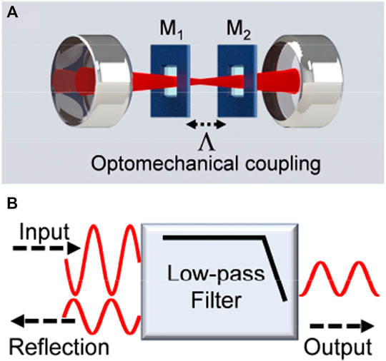
FIGURE 1. (A) Experimental setup of the two-membrane-in-the-middle optomechanical system. M1,2 is the membrane and
The experimental setup is similar to the one used to study the phonon heat transport and coupled-mode heat engine [45, 46]. The difference is that a coherent signal is used, instead of the thermal noise. More specifically, the signal with amplitude modulation (AM) is applied as the input signal upon one nanomechanical membrane through the piezo. The dynamics of two membranes are recorded in real-time by a two-channel lock-in amplifier, as the output and reflection signals, respectively. The schematic diagram of such a phononic low-pass filter is shown in Figure 1B.
3 Theoretical Model
The total Hamiltonian of such a two-membrane-in-the-middle optomechanical system in the rotating frame of the driving laser frequency can be written as
Here
When the damping rate of the cavity mode is much larger than the mechanical damping rates, i.e., κ>>γ1,2, the cavity field follows the dynamics of the mechanical modes adiabatically, and can be eliminated according to Ref. [45]. Consequently, the system can be described by an effective Hamiltonian
Here
is the effective susceptibility introduced by the intracavity field [45–47]. According to Eq. 2, the coupled-mode equations of two mechanical resonators can be obtained as follows
Here,
Eqs 6, 7 can be expressed in the frequency domain
Here,
with
and
Please note that
The magnitude (10Log|R1,2|) and phase shift (arg [R1,2]) of the response function as a function of the modulation frequency in the weak coupling regime are plotted in Figure 2. As one can see in Figure 2, the magnitude has a flat response at a relatively small frequency, and has high attenuation above a specific frequency. By analogy to the electronic low-pass filter, we define the frequency at which the transition occurs, i.e. the cutoff frequency, as the magnitude is reduced by 3dB compared to the DC response. The cutoff frequency is marked in Figures 2A,C, which is ∼10 Hz. Similar to the electronic low-pass filter, a phase shift also exists for such a phononic low-pass filter, which indicates the output signal phase lags behind the reflection or input signal. As one can see in Figures 2B,D, the phase shift is −60 at the cutoff frequency. Compared to the typical passive low-pass filter in electric circuits, the attenuation of such a phononic filter at low frequencies is relatively large. This is due to the relatively large reflection, which means the energy of the input signal partly remains in membrane 1 rather than completely transferring to membrane 2. This situation can be circumvented by introducing mechanical gain and breaking Lorentz reciprocity [20].
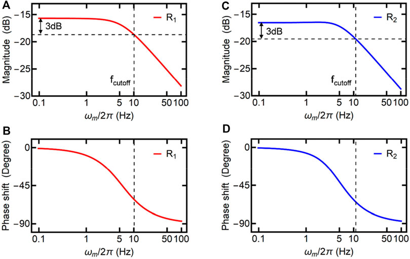
FIGURE 2. (A) The magnitude and (B) the phase shift of the response function R1 as a function of ωm. (C) The magnitude and (D) the phase shift of the response function R2 as a function of ωm. The dashed lines are used to indicate the cutoff frequency. The parameters for the theoretical simulations are Λ = ‒2π×1 Hz, γ1 = 2π×6 Hz, and γ2 = 2π×12 Hz.
When the coupling strength Λ is relatively large, and beyond the critical point, i.e.,
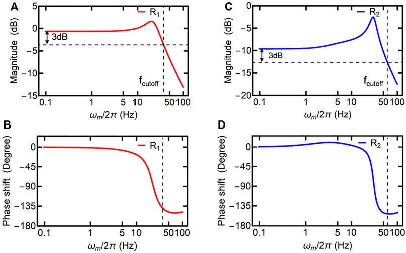
FIGURE 3. (A) The magnitude and (B) the phase shift of the response function R1 as a function of ωm. (C) The magnitude and (D) the phase shift of the response function R2 as a function of ωm. The dashed lines are used to indicate the cutoff frequency. The parameters for the theoretical simulations are Λ = ‒2π×15 Hz, γ1 = 2π×6 Hz, and γ2 = 2π×12 Hz.
4 Experimental Results
The displacements of membranes
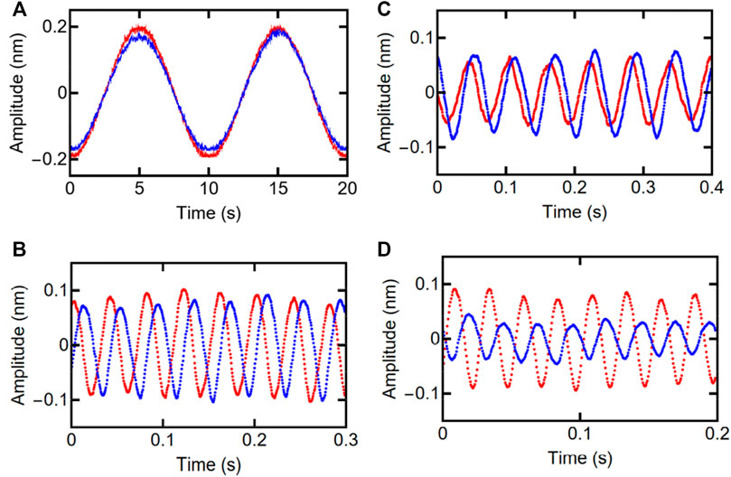
FIGURE 4. The measured signals of two mechanical resonators as a function of time at different modulation frequencies (A) ωm = 2π×0.1 Hz, (B) ωm = 2π×17 Hz, (C) ωm = 2π×25 Hz, and (D) ωm = 2π×40 Hz. The red and blue curves represent the signals measured on membranes 1 and 2, respectively. The parameters for the experimental measurements are Λ = ‒2π×15 Hz, γ1 = 2π×6 Hz, and γ2 = 2π×12 Hz, and M = 0.6.
By extracting the amplitude and phase information of both membranes at different
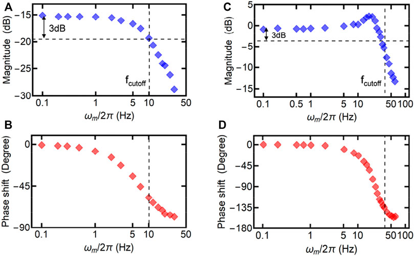
FIGURE 5. (A,B) The measured magnitude and phase shift of the response function R1 as a function of ωm in the weak coupling regime (Λ = ‒2π×1 Hz). (C,D) The measured magnitude and phase shift of the response function R1 as a function of ωm in the strong coupling regime (Λ = ‒2π×15 Hz). The dashed lines are used to indicate the cutoff frequency. Other experimental parameters are the same as in Figure 4.
Figure 6 presents the cutoff frequency derived from R1 as a function of |Λ|. The blue dots are the experimental data and the black curve is the theoretical calculation. According to Figure 6, the cutoff frequency can be widely tuned by changing |Λ|, which can be realized by simply modifying the input laser power. The cutoff frequency approaches a constant (∼10 Hz) when |Λ| is close to zero, and increases linearly at a large |Λ|. Although the cutoff frequency demonstrated in this work is in the range of Hz, the method is universal and the cutoff frequency can be extended to a much higher frequency by using mechanical resonators with frequencies at gigahertz [11].
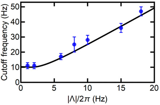
FIGURE 6. The cutoff frequency as a function of optomechanical coupling strength magnitude |Λ|. The blue dots are the experimental measurements and the black curve is the theoretical simulation. The error bars are the standard deviations. Other experimental parameters are the same as in Figure 4.
5 Conclusion
A phononic filter is an important component in the phononic circuits for information processing. We have demonstrated a controllable phononic low-pass filter with cavity optomechanics. The phononic low-pass filter consists of two flexible nanomechanical membranes. The signal applied on one mechanical resonation can be transported to the other over a long distance through light by utilizing cavity-mediated optomechanical interactions. Meanwhile, such a transportation of signal shows a characteristic response function, which is analogous to the low-pass filter in electric circuits. The studies of phononic filters in cavity optomechanical systems could lead to useful tools for classical and quantum information processing.
Data Availability Statement
The original contributions presented in the study are included in the article/Supplementary Material, further inquiries can be directed to the corresponding author.
Author Contributions
CY, JS, and HW carried out the experiment, analyzed the data, developed the theory, and wrote the paper.
Funding
This research was supported by the National Key R&D Program of China (No. 2017YFA0304201), NSFC (Nos. 11925401, 11734008, 11974115, and 11621404), the Shanghai Municipal Science and Technology Major Project (No. 2019SHZDZX01), Natural Science Foundation of Shanghai (No. 22ZR1420400), Natural Science Foundation Project of CQ (No. cstc2021jcyj-msxmX0914).
Conflict of Interest
The authors declare that the research was conducted in the absence of any commercial or financial relationships that could be construed as a potential conflict of interest.
Publisher’s Note
All claims expressed in this article are solely those of the authors and do not necessarily represent those of their affiliated organizations, or those of the publisher, the editors and the reviewers. Any product that may be evaluated in this article, or claim that may be made by its manufacturer, is not guaranteed or endorsed by the publisher.
References
1. Li N, Ren J, Wang L, Zhang G, Hänggi P, Li B. Colloquium: Phononics: Manipulating Heat Flow with Electronic Analogs and beyond. Rev. Mod. Phys. (2012) 84:1045–66. doi:10.1103/revmodphys.84.1045
2. Ghadimi AH, Fedorov SA, Engelsen NJ, Bereyhi MJ, Schilling R, Wilson DJ, et al. Elastic Strain Engineering for Ultralow Mechanical Dissipation. Science (2018) 360:764–8. doi:10.1126/science.aar6939
3. Tsaturyan Y, Barg A, Polzik ES, Schliesser A. Ultracoherent Nanomechanical Resonators via Soft Clamping and Dissipation Dilution. Nat Nanotech (2017) 12:776–83. doi:10.1038/nnano.2017.101
4. Norte RA, Moura JP, Gröblacher S. Mechanical Resonators for Quantum Optomechanics Experiments at Room Temperature. Phys. Rev. Lett. (2016) 116:147202. doi:10.1103/physrevlett.116.147202
5. Reinhardt C, Müller T, Bourassa A, Sankey JC. Ultralow-Noise SiN Trampoline Resonators for Sensing and Optomechanics. Phys. Rev. X (2016) 6:021001. doi:10.1103/physrevx.6.021001
6. O’Connell AD, Hofheinz M, Ansmann M, Bialczak RC, Lenander M, Lucero E, et al. Quantum Ground State and Single-Phonon Control of a Mechanical Resonator. Nature (2010) 464:697. doi:10.1038/nature08967
7. Hong S, Riedinger R, Marinković I, Wallucks A, Hofer SG, Norte RA, et al. Hanbury Brown and Twiss Interferometry of Single Phonons from an Optomechanical Resonator. Science (2017) 358:203–6. doi:10.1126/science.aan7939
8. Kotler S, Peterson GA, Shojaee E, Lecocq F, Cicak K, Kwiatkowski A, et al. Direct Observation of Deterministic Macroscopic Entanglement. Science (2021) 372:622–5. doi:10.1126/science.abf2998
9. Mercier de Lépinay L, Ockeloen-Korppi CF, Woolley MJ, Sillanpää MA. Quantum Mechanics–free Subsystem with Mechanical Oscillators. Science (2021) 372:625. doi:10.1126/science.abf5389
10. Chu Y, Kharel P, Renninger WH, Burkhart LD, Frunzio L, Rakich PT, et al. Quantum Acoustics with Superconducting Qubits. Science (2017) 358:199–202. doi:10.1126/science.aao1511
11. Gustafsson MV, Aref T, Kockum AF, Ekström MK, Johansson G, Delsing P. Propagating Phonons Coupled to an Artificial Atom. Science (2014) 346:207–11. doi:10.1126/science.1257219
12. Mirhosseini M, Sipahigil A, Kalaee M, Painter O. Superconducting Qubit to Optical Photon Transduction. Nature (2020) 588:599–603. doi:10.1038/s41586-020-3038-6
13. Arrangoiz-Arriola P, Alex Wollack E, Pechal M, Witmer JD, Hill JT, Safavi-Naeini AH. Coupling a Superconducting Quantum Circuit to a Phononic Crystal Defect Cavity. Phys. Rev. X (2018) 8:031007. doi:10.1103/physrevx.8.031007
14. Sheng J, Chao Y, Shaffer JP. Strong Coupling of Rydberg Atoms and Surface Phonon Polaritons on Piezoelectric Superlattices. Phys. Rev. Lett. (2016) 117:103201. doi:10.1103/physrevlett.117.103201
15. Metelmann A, Clerk AA. Nonreciprocal Photon Transmission and Amplification via Reservoir Engineering. Phys. Rev. X (2015) 5:021025. doi:10.1103/physrevx.5.021025
16. Tomadin A, Diehl S, Lukin MD, Rabl P, Zoller P. Reservoir Engineering and Dynamical Phase Transitions in Optomechanical Arrays. Phys. Rev. A (2012) 86:033821. doi:10.1103/physreva.86.033821
17. Otterstrom NT, Behunin RO, Kittlaus EA, Rakich PT. Optomechanical Cooling in a Continuous System. Phys. Rev. X (2018) 8:041034. doi:10.1103/physrevx.8.041034
18. Naseem MT, Müstecaplıoğlu ÖE. Ground-state Cooling of Mechanical Resonators by Quantum Reservoir Engineering. Commun. Phys. (2021) 4:95. doi:10.1038/s42005-021-00599-z
19. Li B, Wang L, Casati G. Thermal Diode: Rectification of Heat Flux. Phys. Rev. Lett. (2004) 93:184301. doi:10.1103/physrevlett.93.184301
20. Zhang J, Peng B, Özdemir ŞK, Liu Y-x., Jing H, Lü X-y., et al. Giant Nonlinearity via Breaking Parity-Time Symmetry: A Route to Low-Threshold Phonon Diodes. Phys. Rev. B (2015) 92:115407. doi:10.1103/physrevb.92.115407
21. Kalantar N, Agarwalla BK, Segal D. Harmonic Chains and the Thermal Diode Effect. Phys. Rev. E (2021) 103:052130. doi:10.1103/PhysRevE.103.052130
22. Kargı C, Naseem MT, Opatrný T, Müstecaplıoğlu ÖE, Kurizki G. Quantum Optical Two-Atom Thermal Diode. Phys. Rev. E (2019) 99:042121. doi:10.1103/PhysRevE.99.042121
23. Wang L, Li B. Thermal Logic Gates: Computation with Phonons. Phys. Rev. Lett. (2007) 99:177208. doi:10.1103/physrevlett.99.177208
24. Wang L, Li B. Thermal Memory: A Storage of Phononic Information. Phys. Rev. Lett. (2008) 101:267203. doi:10.1103/physrevlett.101.267203
25. Bagheri M, Poot M, Li M, Pernice WPH, Tang HX. Dynamic Manipulation of Nanomechanical Resonators in the High-Amplitude Regime and Non-volatile Mechanical Memory Operation. Nat Nanotech (2011) 6:726–32. doi:10.1038/nnano.2011.180
26. Merklein M, Stiller B, Vu K, Madden SJ, Eggleton BJ. A Chip-Integrated Coherent Photonic-Phononic Memory. Nat Commun (2017) 8:574. doi:10.1038/s41467-017-00717-y
27. Sheng J, Wei X, Yang C, Wu H. Self-Organized Synchronization of Phonon Lasers. Phys. Rev. Lett. (2020) 124:053604. doi:10.1103/PhysRevLett.124.053604
28. Fu W, Shen Z, Xu Y, Zou C-L, Cheng R, Han X, et al. Phononic Integrated Circuitry and Spin-Orbit Interaction of Phonons. Nat Commun (2019) 10:2743. doi:10.1038/s41467-019-10852-3
29. Taylor JC, Kindel WF, Chatterjee E, Kindel WF, Soh D, Eichenfield M. Reconfigurable Quantum Phononic Circuits via Piezo-Acoustomechanical Interactions. npj Quantum Inf (2022) 8:19. doi:10.1038/s41534-022-00526-2
30. Hatanaka D, Mahboob I, Onomitsu K, Yamaguchi H. Phonon Waveguides for Electromechanical Circuits. Nat Nanotech (2014) 9:520–4. doi:10.1038/nnano.2014.107
31. Safavi-Naeini AH, Painter O. Design of Optomechanical Cavities and Waveguides on a Simultaneous Bandgap Phononic-Photonic Crystal Slab. Opt. Express (2010) 18:14926. doi:10.1364/oe.18.014926
33. Wyatt AFG, Lockerbie NA, Sherlock RA. LiquidHe4: A Tunable High-Pass Phonon Filter. Phys. Rev. Lett. (1974) 33:1425–8. doi:10.1103/physrevlett.33.1425
34. Narayanamurti V, Störmer HL, Chin MA, Gossard AC, Wiegmann W. Selective Transmission of High-Frequency Phonons by a Superlattice: The "Dielectric" Phonon Filter. Phys. Rev. Lett. (1979) 43:2012–6. doi:10.1103/physrevlett.43.2012
35. Lin L, Howe RT, Pisano AP. Microelectromechanical Filters for Signal Processing. J. Microelectromech. Syst. (1998) 7:286–94. doi:10.1109/84.709645
36. Hajhashemi MS, Amini A, Bahreyni B. A Micromechanical Bandpass Filter with Adjustable Bandwidth and Bidirectional Control of Centre Frequency. Sensors Actuators A Phys (2012) 187:10–5. doi:10.1016/j.sna.2012.08.008
37. Ilyas S, Chappanda KN, Younis MI. Exploiting Nonlinearities of Micro-machined Resonators for Filtering Applications. Appl. Phys. Lett. (2017) 110:253508. doi:10.1063/1.4986921
38. D’Alessandro L, Belloni E, Ardito R, Braghin F, Corigliano A. Mechanical Low-Frequency Filter via Modes Separation in 3D Periodic Structures. Appl. Phys. Lett. (2017) 111:231902. doi:10.1063/1.4995554
39. Dong Y, Yao H, Du J, Zhao J, Ding C. Research on Bandgap Property of a Novel Small Size Multi-Band Phononic Crystal. Phys Lett A (2019) 383:283–8. doi:10.1016/j.physleta.2018.10.042
40. Chen Z-G, Zhao J, Mei J, Wu Y. Acoustic Frequency Filter Based on Anisotropic Topological Phononic Crystals. Sci Rep (2017) 7:15005. doi:10.1038/s41598-017-15409-2
41. Piergentili P, Catalini L, Bawaj M, Zippilli S, Malossi N, Natali R, et al. Two-membrane Cavity Optomechanics. New J. Phys. (2018) 20:083024. doi:10.1088/1367-2630/aad85f
42. Gärtner C, Moura JP, Haaxman W, Norte RA, Gröblacher S. Integrated Optomechanical Arrays of Two High Reflectivity SiN Membranes. Nano Lett. (2018) 18:7171–5. doi:10.1021/acs.nanolett.8b03240
43. Wei X, Sheng J, Yang C, Wu Y, Wu H. Controllable Two-Membrane-In-The-Middle Cavity Optomechanical System. Phys. Rev. A (2019) 99:023851. doi:10.1103/physreva.99.023851
44. Wu S, Sheng J, Zhang X, Wu Y, Wu H. Parametric Excitation of a SiN Membrane via Piezoelectricity. AIP Adv (2018) 8:015209. doi:10.1063/1.5009952
45. Yang C, Wei X, Sheng J, Wu H. Phonon Heat Transport in Cavity-Mediated Optomechanical Nanoresonators. Nat Commun (2020) 11:4656. doi:10.1038/s41467-020-18426-4
46. Sheng J, Yang C, Wu H. Realization of a Coupled-Mode Heat Engine with Cavity-Mediated Nanoresonators. Sci Adv (2021) 7:eabl7740. doi:10.1126/sciadv.abl7740
Keywords: cavity optomechanics, phononic device, multimode optomechanical system, silicon nitride membrane, phonon filter
Citation: Yang C, Sheng J and Wu H (2022) Controllable Phononic Low-Pass Filter via Optomechanical Interactions. Front. Phys. 10:904467. doi: 10.3389/fphy.2022.904467
Received: 25 March 2022; Accepted: 19 April 2022;
Published: 04 May 2022.
Edited by:
Liu Yang, Harbin Engineering University, ChinaCopyright © 2022 Yang, Sheng and Wu. This is an open-access article distributed under the terms of the Creative Commons Attribution License (CC BY). The use, distribution or reproduction in other forums is permitted, provided the original author(s) and the copyright owner(s) are credited and that the original publication in this journal is cited, in accordance with accepted academic practice. No use, distribution or reproduction is permitted which does not comply with these terms.
*Correspondence: Jiteng Sheng, anRzaGVuZ0BscHMuZWNudS5lZHUuY24=