- 1School of Mechanical Engineering and Automation, Dalian Polytechnic University, Dalian, China
- 2The School of Information Science and Engineering, Dalian Polytechnic University, China
In recent years, with the in-depth study of the memristor, meminductor, and memcapacitor, the fourth basic element has been developed vigorously. The chaotic circuit including the meminductor, memcapacitor, and memristor is designed in this study. The equation of state for the chaotic system is obtained according to Kirchhoff’s volt–current law, and the mathematical model of the chaotic system is obtained through dimensionless processing. The stability of the equilibrium point is analyzed in detail, and the dynamic behaviors of the system are analyzed by traditional methods such as LEs and bifurcation diagram. Moreover, some special phenomena exist in the system, such as state transition and coexistence of attractors. Finally, the circuit is implemented by DSP to prove the realizability of chaotic circuit.
Introduction
A chaotic system is a kind of complex nonlinear dynamic system, and its motion has pseudo-randomness. The orbit moves in a specific range but never repeats. Chaos is often described as a specific phenomenon with an infinite period or a phenomenon similar to random behavior. According to the growing understanding of chaos, people found that chaos includes not only integer-order chaotic system but also fractional-order chaotic system [1–7].In addition, people usually study chaos by constructing chaotic circuits. The nonlinear element is an important part of the nonlinear system.
The memristor is a kind of nonlinear element [8]. Professor Chua presented a special circuit element and suggested that it could be used to describe the relationship between charge value and magnetic flux in 1971 and it is called a memristor [9]. From then on, Professor Chua proposed the concept of memristor for several decades, and no memristor element has been found in practice. So research on the fourth basic element has been stalled. Until 2008, the HP Laboratory in the United States claimed to have completed the hardware realization of memristor components on the nanoscale for the first time, which eventually led to booming research on the fourth type of components [10, 11]. Many research studies on chaotic circuits are carried out from this [12–16]. However, at present, because the hardware implementation of the memristor in the real sense can only be completed at the laboratory level, the application research of the memristor is mainly based on its mathematical model or the circuit equivalent model.
Through continuous research on the memristor, in 2009, Professor Chua presented the meminductor and memcapacitor, two memory elements, which further deepen the research on nonlinear systems. Although the basic principles of meminductor and memcapacitor components have been understood, there is no material that can be used to manufacture these two basic components in nature, so the hardware implementation of the meminductor and memcapacitor is still at a standstill until now. However, due to its unique memory characteristics, many theoretical analyses and research studies on meminductor and memcapacitor components have been completed. The chaotic circuits based on the meminductor and memcapacitor are rarely reported [17–20].
Because of their distinctively dynamic characteristics, the memristor, meminductor, and memcapacitor have been used in chaotic systems. In 2008, a memristor was used to replace Chua’s diode to design the chaotic system, and numerical simulation analysis and circuit implementation were carried out [21]. In 2012, Professor Chua first proposed a simple-series chaotic circuit based on a memristor and implemented it. The circuit consists only of a memristor, an inductor, and a capacitor in series [22]. In 2013, Professor Xu modified the simplest chaotic circuit. By connecting the inductor, memristor, and capacitor in parallel, he proposed a minimalist parallel chaotic circuit and simulated it [23]. In 2019, Professor Yuan constructed the simplest parallel chaotic circuit by connecting the memcapacitor, meminductor, and memristor in parallel. Its dynamic characteristics were not only analyzed but also the circuit simulation was carried out [24]. The chaotic system based on the memristor and other memory elements has better application in a neural network, chaotic secure communication, and image encryption due to its excellent dynamic characteristics [25–39].
In this study, a chaotic system including the meminductor, memcapacitor, and memristor is proposed. Because of the special dynamic characteristics of the memristor, meminductor, and memcapacitor, compared with the general chaotic oscillator, it has more dynamic characteristics [40–43]. Finally, digital circuits are less affected by the environment and have greater flexibility in parameter changes. Therefore, a complete set of dynamic analyses and implementation of a chaotic oscillator is carried out by DSP in this study to prove the realizability of the circuit [44–52].
The rest of the study follows according to the abovementioned background. In the second section, the model of the memcapacitor, memristor, and meminductor is presented. In the third section, the state equation is determined by the constructed chaotic circuit, the stability of the equilibrium point is analyzed, and the dynamical characteristics of the system are analyzed through the traditional way. In the fourth section, the circuit is implemented by DSP. In the fifth section, the relevant work of this study is summarized.
Models of the Memcapacitor, Meminductor, and Memristor
Model of the Memristor
This study uses the model of the classic memristor proposed by Professor Chua [53]. The equation of state is shown below:
In the equation, iM represents the current of the memristor, VM represents the voltage of the memristor, b and a represent the parameters, and y represents the state variables of the memristor.
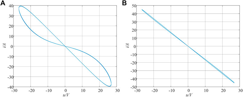
An AC power supply with a frequency of 10 Hz is assumed and an effective value of 10 A is input at both ends of the memristor. Through numerical simulation of the memristor, we can obtain its v-i memory curve, as shown in Figure 1A. The simulation results show that its characteristic curve is a compact “8″ hysteretic curve. As the frequency increases, the side lobe area of the characteristic curve decreases. This is consistent with the basic characteristics of the memristor proposed by Professor Chua.
Model of the Memcapacitor
By professor Chua’s definition of the memcapacitor, it is a passive memory element [54]. According to the definition of the memcapacitor, the current passing through it can be expressed as i, the charge gathered at both ends of the memcapacitor can be expressed as q, and the time integral of charge quantity q can be expressed as σ. So, the state equation of the memcapacitor element is shown as follows:
For the model of the memcapacitor mentioned above, when the input of the memcapacitor is an AC power supply with a frequency of 10 Hz and an effective value of 2A, the curve of the dynamic characteristic of the memcapacitor can be obtained through numerical simulation, as shown in Figure 2. This is a compact hysteresis curve with a shape similar to an inclined “8”, and the side lobe area decreases with increasing frequency. This is consistent with the basic properties of memcapacitors.
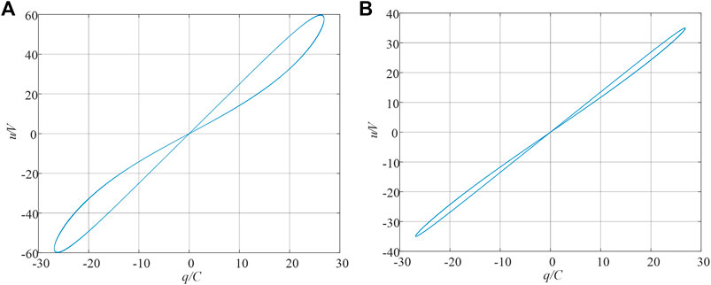
FIGURE 2. Hysteresis curve of the memcapacitor, (A) c = 1.7, d = 2, f = 10 Hz. (B) c = 1.7, d = 2, f = 80 Hz.
Model of the Meminductor
By professor Chua’s definition of the meminductor [54], its model used in this study is as follows:
The ρ in the equation is the integral of magnetic flux φ, where e and g represent the internal parameters of the meminductor.
A sinusoidal signal with a magnetic flux of 10 Wb and a frequency of 5 Hz is applied at both ends of the meminductor, and the characteristic curve of the meminductor element Φ-i is shown in Figure 3A. The curve of the meminductor is also a slanted hysteresis curve similar to “8”. Through numerical simulation, it was found that the sidelobe area of the characteristic curve of the meminductor gradually decreased with the increase of input frequency, which was consistent with the dynamic characteristics of the meminductor proposed by Professor Chua.
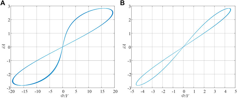
FIGURE 3. Hysteresis curve of the meminductor, (A) e = 1, g = 1, f = 5 Hz. (B) e = 1, g = 1, f = 20 Hz.
A New Simple Chaotic Oscillator
A New Chaotic Oscillator
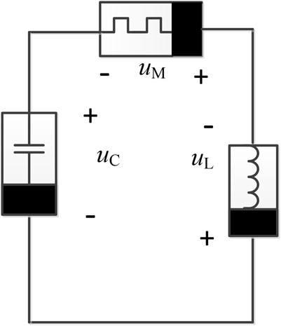
In this circuit, there are three nonlinear elements, namely, an independent charge-controlled memcapacitor, a charge-controlled memristor, and a meminductor. The circuit can be expressed as Figure 4:
The circuit includes three kinds of nonlinear elements, meminductor, memristor, and memcapacitor. Suppose the charge flowing through the memcapacitor is q, φ denotes the magnetic flux, the internal state variable of the memristor is y, the time integral of the charge quantity q is denoted as σ, and the time integral of the magnetic flux φ is denoted as ρ. Then, according to the characteristic equations of each nonlinear element and Kirchhoff’s voltage–current law, the equation of the circuit was obtained as follows:
Five nonlinear equations are included in system (4), which contains five variables φ, y, q, σ, and ρ. Set σ = u, φ = x, q = z, y = y, and ρ = w. Moreover, dimensionless processing is performed on Eq. 4, and then Eq. 4 becomes
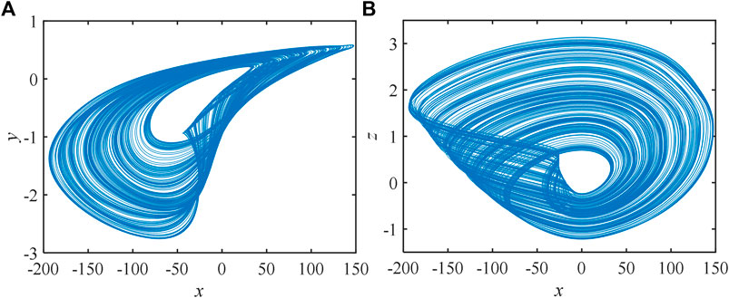
When the initial conditions are set as (1, 40, 1.5, 20, -15) and the parameters are set as b = 20, a = 49, g = 2, e = 100, c = 0.2, and d = -0.02, the phase diagram simulated by MATLAB is expressed in Figure 5.
Equilibrium Point Set and Stability
The calculation method of divergence of the chaotic system is shown as
For the parameters set as a = 49, b = 20, g = 2, e = 100, c = 0.2, and d = -0.02. The divergence of the system is calculated to be -16,881. This means that the system can produce chaos.
Let the system state variable
Through calculation, the equilibrium point of the system is obtained as O(0, 0, 0, n, m). It shows that the system had an infinite number of equilibrium points. According to Eq. 7, the Jacobian matrix JE of the system can be obtained
Therefore, the characteristic polynomial of the system can be obtained through the Jacobian matrix of the system.
where m1 = b-a(c + dcosm), m2 = [(c + dcosm) (e + gn)-ab(c + dcosm)], and m3 = b((c + dcosm) (c + dn)).
Equation 9 means system (5) has three non-zero eigenvalues and one zero eigenvalue, where m1, m2, and m3 are coefficients. By the Routh–Hurwitz criterion, system (5) is stable if m1 > 0, m1m2-m3>0, and m3(m1m2-m3)>0. At least one of the eigenvalues of the chaotic systems is positive, so the m1, m1m2m3, and m3 should be not all positive. So, we could set O such as O1 (0, 0, 0, 20, -15). Let the parameters be a = 49, b = 20, g = 2, e = 100, c = 0.2, and d = -0.02, and we can get m1 = 9.4552 > 0, m2 = -180.768 > 0, m3 = 602.56 > 0, m1m2-m3<0, m3(m1m2-m3)<0 and λ1 = λ2 = 0, λ3 = -20, λ4 = 5.2722 + 1.5266i, λ5 = 5.2722–1.5266i. This means that the system is unstable, and it is possible for such a system to produce chaos.
The Impact of the Parameters
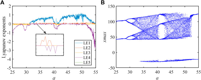
To display the dynamical behaviors of the system designed by us more directly, we use the bifurcation diagram and LEs to study the dynamic behaviors of the system when parameter a changes. Other parameters of the chaotic system are set as d = -0.02, g = 2, e = 100, b = 20, and c = 0.2, and the initial condition is 1, 40, 1.5, 20, and -15. The calculation results are as follows Figure 6.
According to the LEs and bifurcation diagram, we can understand that the bifurcation diagram and LEs can correspond to each other. According to the definition of LEs, the system has two positive Lyapunov exponents in a certain parameter range, which shows that the system is a hyperchaotic system. According to the bifurcation diagram, with the change of parameter a, the system enters into a chaotic state by means of period-doubling bifurcation.
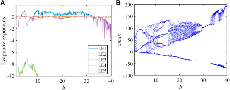
To study the dynamic behaviors of the simple system parameter b is treated as a variable. Other parameters are set as a = 49, g = 2, e = 100, c = 0.2, and d = −0.02, and the initial values are 1, 40, 1.5, 20, and −15. The results of numerical simulation are expressed in Figure 7.
By observing the LEs, we can see that the bifurcation diagram and LEs agree perfectly. From LEs, we can find simply that the system not only has a chaotic state but also has a hyperchaotic state. According to the bifurcation diagram, when the parameter b increases, the system enters into chaos by period-doubling bifurcation.
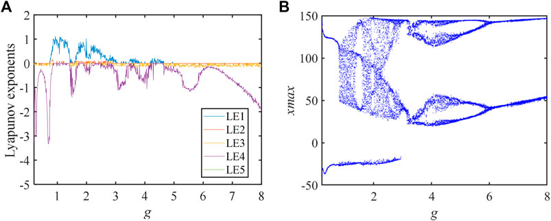
When the system parameters a = 49, b = 20, e = 100, c = 0.2, and d = −0.02 and the initial values are 1, 40, 1.5, 20, −15, just the parameter g is changed. The bifurcation diagram and LEs are expressed in Figure 8.
By the analysis of LEs, we can know that when the parameter g increases, the system changes frequently between periodic state, chaotic state, and hyperchaotic state. Also, the system is produced by a counter-periodic doubling of the chaotic state. The bifurcation diagram and LEs agree well.
Complexity Analysis
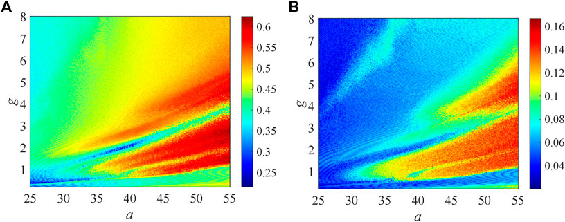
The chaotic state and hyperchaotic state are the most valuable intervals of a chaotic system. When the system is chaotic or hyperchaotic, the sequence generated by the system has high pseudo-randomness, which makes the system have good anti-decoding performance. When the system shows higher complexity, its dynamic performance is also superior. So, in image encryption, people mostly choose the parameter range with higher complexity. To further understand the dynamic behaviors, two complexity algorithms C0 and SE(spectral entropy) are used to analyze the system complexity. The results show that the SE and C0 algorithms reflect the dynamic behaviors. The initial values are set as 1, 40, 1.5, 20, and -15 and the system parameters b = 20, e = 100, d = -0.02, c = 0.2 are kept unchanged. Only the system parameters a and g are changed. As system parameters a and g change, SE and C0 complexity is shown in Figures 9A,B. When the system parameters a = [24, 54] and g = (0.2, 8), the complexity value of the chaotic system changes with parameters a and g, as shown in Figure 9, and the periodic state and chaotic state of the system can be clearly displayed. By analyzing the complexity of the system, we can know the changing rules of the dynamical characteristics of the system. Also, because these two complexity algorithms are calculated based on the FFT complexity algorithm, their variation trend is roughly the same.
State Transition
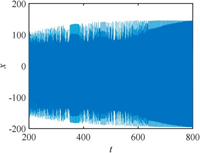
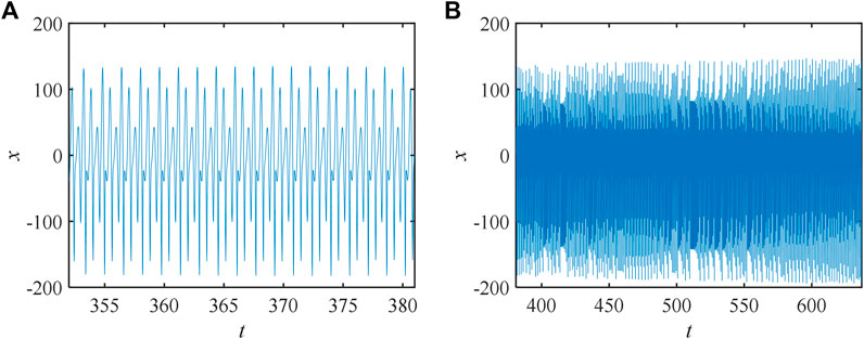
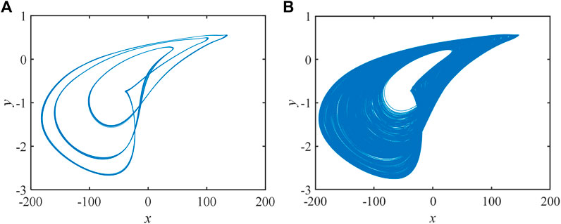
Leaving the initial values and parameters unchanged, when the state changes with time, this phenomenon is called state transition. The special phenomenon of state transition exists in the system constructed in the study. Let the system parameters a = 49, g = 2, e = 100, c = 0.2, d = −0.02, and b = 20 and the initial condition be 1, 40, 1.5, 20, and −15. The timing diagram of the system is expressed in Figure 10:
The detailed sequence diagram of periodic and chaotic states is expressed in Figure 11:
When t = [352, 381] and t = [381, 637], the simulation results are shown as follows Figure 12:
Coexistence of Attractors
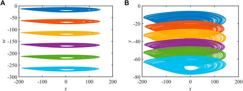
Coexistence of attractors is a special phenomenon of chaotic systems [55–57]. For the chaotic circuit system with the memristor, meminductor, and memcapacitor, let a = 49, b = 20, e = 100, c = 0.2, d = -0.02, g = 2, and simulation step t = 0.001s. In addition, let the initial condition be 1, 20, z0, 20, and w0. When the initial value is changed, the results are shown in Figure 13:
The initial value is set to (1, 40, 1.5, 20, −15), (1, 40, 11.5, 20, −15), (1, 40, 21.5, 20, −15), (1, 40, 31.5, 20, −15), (1, 40, 41.5, 20, −15) and (1, 40, 51.5, 20, −15). The simulation results of the system are shown in Figure 13A:
Let the initial values be (1, 40, 1.5, 20, −15), (1, 40, 1.5, 20, −25), (1, 40, 1.5, 20, −35), (1, 40, 1.5, 20, −45), (1, 40, 1.5, 20, −55) and (1, 40, 1.5, 20, −65), and the numerical simulation results are expressed in Figure 13B.
DSP Implementation
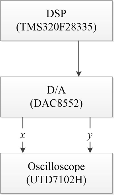
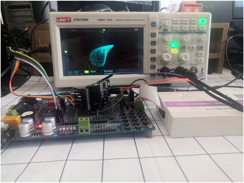
Because DSP implementation has strong anti-interference ability, the parameters in the system are also better controlled. The DSP is called digital signal processor. Digital signal processing is the use of computers or special processing equipment in the digital form of signal acquisition, transformation, filtering, valuation, enhancement, compression, recognition, and other processing in order to get the signal form that meets people’s needs. We choose to use the DSP to achieve the chaotic system. However, because of the limited precision of DSP hardware implementation, we choose the TMS320F28335 chip so as to meet the requirements of system precision. To make the oscilloscope capture the image more easily, we use a D/A converter to convert the DSP-generated sequence into the analog sequence and then transmit the signal to the oscilloscope (UTD7102H) through the D/A converter (8552). The flow chart of DSP implementation is shown in Figure 14.
Let its parameters be a = 49, b = 20, e = 100, c = 0.2, d = −0.02, and g = 2. The initial value is (1, 40, 1.5, 20, −15). First, the parameters and initial value are set and then iterative calculation is started. The data generated by each iteration are stored using stack techniques to avert corruption. The results of DSP implementation are shown in Figure 15.
Hardware such as oscilloscope, D/A converter, and F28335 chip used in DSP implementation are expressed in Figure 16.
Conclusion
In this study, the circuit with the memcapacitor, memristor, and meminductor is constructed. The study not only introduces the model of the meminductor, memcapacitor, and memristor but also obtains the dynamics equation of the system by Kirchhoff’s voltage–current law. The stability of the equilibrium point is analyzed by means of traditional dynamics. Through the analysis of LEs, complexity, and bifurcation diagram, it is found that when the initial conditions and parameters change, the chaotic system shows complex dynamical behavior. Also, the system has not only a chaotic state but also a hyperchaotic state. In addition, some special phenomena such as state transition and coexistence of attractors are found in the analysis of the systems. Finally, the DSP is used to realize the chaotic circuit, and the simulation diagram in the DSP is highly consistent with the results of numerical simulation. The rich dynamic characteristics show that it can be used in chaotic image encryption.
Data Availability Statement
The original contributions presented in the study are included in the article/Supplementary Materials, further inquiries can be directed to the corresponding author.
Author Contributions
XL designed and carried out experiments, analyzed data, and wrote the manuscript. JW made the theoretical guidance for this study. All authors reviewed the manuscript.
Funding
This work was supported by the National Natural Science Foundation of China (Grant Nos. 62061014 and 61773010); the Natural Science Foundation of Liaoning province (2020-MS-274); the Basic Scientific Research Projects of Colleges and Universities of Liaoning Province (Grant No. J202148).
Conflict of Interest
The authors declare that the research was conducted in the absence of any commercial or financial relationships that could be construed as a potential conflict of interest.
Publisher’s Note
All claims expressed in this article are solely those of the authors and do not necessarily represent those of their affiliated organizations, or those of the publisher, the editors, and the reviewers. Any product that may be evaluated in this article, or claim that may be made by its manufacturer, is not guaranteed or endorsed by the publisher.
References
1. Zhang D, Zhao A, Yang X, Sun Y, Xiao J. Generalized Synchronization between Chen System and Rucklidge System. IEEE Access (2019) 7:8519–26. doi:10.1109/access.2018.2890311
2. Liu X, Bi X, Yan H. A Chaotic Oscillator Based on Meminductor, Memcapacitor, and Memristor[J]. Complexity (2021) 1. doi:10.1155/2021/7223557
3. Liu T, Yan H, Banerjee S, Mou J. A Fractional-Order Chaotic System with Hidden Attractor and Self-Excited Attractor and its DSP Implementation. Chaos, Solit Fractals (2021) 145:110791. doi:10.1016/j.chaos.2021.110791
4. Liu T, Banerjee S, Yan H, Mou J. Dynamical Analysis of the Improper Fractional-Order 2D-SCLMM and its DSP Implementation. Eur. Phys. J. Plus (2021) 136(5):506. doi:10.1140/epjp/s13360-021-01503-y
5. Ma C, Mou J, Li P, Liu T. Dynamic Analysis of a New Two-Dimensional Map in Three Forms: Integer-Order, Fractional-Order and Improper Fractional-Order. Eur Phys J Special Top (2021) 230(7):1945–57. doi:10.1140/epjs/s11734-021-00133-w
6. Peng Y, He S, Sun K. Parameter Identification for Discrete Memristive Chaotic Map Using Adaptive Differential Evolution Algorithm[J]. Nonlinear Dyn(2021) 1–13.
7. Ma C, Mou* J, Xiong L, Banerjee S, Liu T, Han X. Dynamical Analysis of a New Chaotic System: Asymmetric Multistability, Offset Boosting Control and Circuit Realization. Nonlinear Dyn(2021) 103(3):2867–80. doi:10.1007/s11071-021-06276-8
8. Prodromakis T, Peh BP, Papavassiliou C, Toumazou C. A Versatile Memristor Model with Nonlinear Dopant Kinetics. IEEE Trans. Electron Devices (2011) 58(9):3099–105. doi:10.1109/ted.2011.2158004
9. Chua L. Memristor-the Missing Circuit Element. IEEE Trans. Circuit Theory (1971) 18(5):507–19. doi:10.1109/tct.1971.1083337
10. Strukov DB, Snider GS, Stewart DR, Williams RS. The Missing Memristor Found. Nature (2008) 453(7191):80–3. doi:10.1038/nature06932
12. Li C, Li H, Xie W, Du J. A S-type Bistable Locally Active Memristor Model and its Analog Implementation in an Oscillator Circuit. Nonlinear Dyn(2021) 106(1):1041–58. doi:10.1007/s11071-021-06814-4
13. Liu J, Chen G, Zhao X. Generalized Synchronization and Parameters Identification of Different-Dimensional Chaotic Systems in the Complex Field[J]. Fractals (2021) 29(4):2150081–824. doi:10.1142/s0218348x2150081x
14. Li Y, Li C, Zhang S. A Self-Reproduction Hyperchaotic Map with Compound Lattice Dynamics[J]. IEEE Trans Industrial Electron (2022):1. doi:10.1109/tie.2022.3144592
15. Li Y, Li C, Zhao Y, Liu S. Memristor-type Chaotic Mapping. Chaos (2022) 32(2):021104. doi:10.1063/5.0082983
16. Zhang X, Li C, Dong E. A Conservative Memristive System with Amplitude Control and Offset Boosting[J]. Int J Bifurcation Chaos (2022) 32(04):2250057. doi:10.1142/s0218127422500572
17. ZhenYu Yin ZY, Heng Tian H, GuanHua Chen GH, Chua LO. What Are Memristor, Memcapacitor, and Meminductor? IEEE Trans. Circuits Syst. II (2015) 62(4):402–6. doi:10.1109/tcsii.2014.2387653
18. Ma X, Mou J, Liu J, Ma C, Yang F, Zhao X. A Novel Simple Chaotic Circuit Based on Memristor-Memcapacitor. Nonlinear Dyn(2020) 100(3):2859–76. doi:10.1007/s11071-020-05601-x
19. Hu Z, Li Y, Li J, Yu J. Chaotic Oscillator Based on Voltage-Controlled Memcapacitor. In: International Conference on Communications (2010). doi:10.1109/icccas.2010.5581863
20. Feali MS, Ahmadi A, Hayati M. Implementation of Adaptive Neuron Based on Memristor and Memcapacitor Emulators. Neurocomputing (2018) 309(OCT.2):157–67. doi:10.1016/j.neucom.2018.05.006
21. Itoh M, Chua LO. Memristor Oscillators. Int. J. Bifurc Chaos (2008) 18(11):3183–206. doi:10.1142/s0218127408022354
23. Xu B, Wang G, Shen Y. A Simple Meminductor-Based Chaotic System with Complicated Dynamics. Nonlinear Dyn(2017) 88(3):2071–89. doi:10.1007/s11071-017-3363-y
24. Yuan F, Li Y. A Chaotic Circuit Constructed by a Memristor, a Memcapacitor and a Meminductor. Chaos (2019) 29(10):101101. doi:10.1063/1.5125673
25. Yu F, Zhang Z, Shen H, Huang Y, Cai S, Du S. FPGA Implementation and Image Encryption Application of a New PRNG Based on a Memristive Hopfield Neural Network with a Special Activation Gradient. Chin Phys. B (2022) 31(2):020505. doi:10.1088/1674-1056/ac3cb2
26. Li C, Yang Y, Yang X. A Tristable Locally Active Memristor and its Application in Hopfield Neural Network[J]. Nonlinear Dyn(2022) 108:1697–717. doi:10.1007/s11071-022-07268-y
27. Zhou Y, Li C, Li W, Li H, Feng W, Qian K. Image Encryption Algorithm with Circle Index Table Scrambling and Partition Diffusion. Nonlinear Dyn(2021) 103(2):2043–61. doi:10.1007/s11071-021-06206-8
28. Li C-L, Zhou Y, Li H-M, Feng W, Du J-R. Image Encryption Scheme with Bit-Level Scrambling and Multiplication Diffusion. Multimed Tools Appl (2021) 80(12):18479–501. doi:10.1007/s11042-021-10631-7
29. Yu F, Shen H, Zhang Z, Huang Y, Cai S, Du S. A New Multi-Scroll Chua's Circuit with Composite Hyperbolic Tangent-Cubic Nonlinearity: Complex Dynamics, Hardware Implementation and Image Encryption Application. Integration (2021) 81:71–83. doi:10.1016/j.vlsi.2021.05.011
30. Yu F, Zhang Z, Shen H. Design and FPGA Implementation of a Pseudo-random Number Generator Based on a Hopfield Neural Network under Electromagnetic Radiation[J]. Front Phys (2021) 9:302. doi:10.3389/fphy.2021.690651
31. Yang F, Mou J, Ma C, Cao Y. Dynamic Analysis of an Improper Fractional-Order Laser Chaotic System and its Image Encryption Application. Opt Lasers Eng (2020) 129(2020):106031. doi:10.1016/j.optlaseng.2020.106031
32. Li X, Mou J, Xiong L, Wang Z, Xu J. Fractional-order Double-Ring Erbium-Doped Fiber Laser Chaotic System and its Application on Image Encryption. Opt Laser Technol (2021) 140(2021):107074. doi:10.1016/j.optlastec.2021.107074
33. Xian Y, Wang X. Fractal Sorting Matrix and its Application on Chaotic Image Encryption. Inf Sci (2021) 547:1154–69. doi:10.1016/j.ins.2020.09.055
34. Yu F, Kong X, Chen H. A 6D Fractional-Order Memristive Hopfield Neural Network and its Application in Image Encryption[J]. Front Phys (2022) 10:109. doi:10.3389/fphy.2022.847385
35. Gao X. An Effective Multiple-Image Encryption Algorithm Based on 3D Cube and Hyperchaotic Map. Journal of King Saud University-Computer and Information Sciences (2022).
36. Li X. An Optical Image Encryption Algorithm Based on a Fractional-Order Laser Hyperchaotic System. Int J Bifurcation Chaos (2022) 3203:2250035. doi:10.1142/s0218127422500353
37. Gao X. A Fast and Efficient Multiple Images Encryption Based on Single-Channel Encryption and Chaotic System. Nonlinear Dyn(2022) 108:613. doi:10.1007/s11071-021-07192-7
38. Zhou S, Wang X, Zhang Y, Ge B, Wang M, Gao S. A Novel Image Encryption Cryptosystem Based on True Random Numbers and Chaotic Systems. Multimed Syst (2022) 28(1):95–112. doi:10.1007/s00530-021-00803-8
39. Zhou S, Wang X, Wang M, Zhang Y. Simple Colour Image Cryptosystem with Very High Level of Security. Chaos, Solit Fractals (2020) 141:110225. doi:10.1016/j.chaos.2020.110225
40. Wang H, Wang X, Li C. SPICE Mutator Model for Transforming Memristor into Meminductor[J. ]. Abstr Appl Analysis (2013) 168–84. doi:10.1155/2013/281675
41. Zhao Q, Wang C, Zhang X. A Universal Emulator for Memristor, Memcapacitor, and Meminductor and its Chaotic Circuit. Chaos (2019) 29:013141. doi:10.1063/1.5081076
42. Yuan F, Deng Y, Li Y, Wang G. The Amplitude, Frequency and Parameter Space Boosting in a Memristor-Meminductor-Based Circuit. Nonlinear Dyn(2019) 96:389–405. doi:10.1007/s11071-019-04795-z
43. Han B, Liu W, Hu A, Bao H, Liu W, Hu A. Coexisting Multiple Firing Patterns in Two Adjacent Neurons Coupled by Memristive Electromagnetic Induction. Nonlinear Dyn(2019) 95:43–56.
44. Chen A, Lu J, Lü J, Yu S. Generating Hyperchaotic Lü Attractor via State Feedback Control. Phys A Stat Mech its Appl (2006) 364:103–10. doi:10.1016/j.physa.2005.09.039
45. Mahmoud GM, Mahmoud EE, Ahmed ME. On the Hyperchaotic Complex Lü System. Nonlinear Dyn(2009) 58(4):725–38. doi:10.1007/s11071-009-9513-0
46. Wang Z, Cang S, Ochola EO. A Hyperchaotic System without Equilibrium[J]. Nonlinear Dyn(2012) 69(1):531–7. doi:10.1007/s11071-011-0284-z
47. Yang F, Mou J, Liu J, Ma C, Yan H. Characteristic Analysis of the Fractional-Order Hyperchaotic Complex System and its Image Encryption Application. Signal Process(2020) 169:107373. doi:10.1016/j.sigpro.2019.107373
48. Zhang X, Wang C. Multiscroll Hyperchaotic System with Hidden Attractors and its Circuit Implementation. Int. J. Bifurc Chaos (2019) 29(09):1950117. doi:10.1142/s0218127419501177
49. Yu W, Wang J, Wang J, Zhu H, Li M, Li Y, et al. Design of a New Seven-Dimensional Hyperchaotic Circuit and its Application in Secure Communication. IEEE Access (2019) 7:125586–608. doi:10.1109/access.2019.2935751
50. He S, Sun K, Wang H, Mei X, Sun Y. Generalized Synchronization of Fractional-Order Hyperchaotic Systems and its DSP Implementation. Nonlinear Dyn(2018) 92(1):85–96. doi:10.1007/s11071-017-3907-1
51. He S, Sun K, Wang H. Complexity Analysis and DSP Implementation of the Fractional-Order Lorenz Hyperchaotic System. Entropy (2015) 17(12):8299–311. doi:10.3390/e17127882
52. Dai S, Sun K, Ai W, Peng Y. Novel Discrete Chaotic System via Fractal Transformation and its DSP Implementation. Mod. Phys. Lett. B (2020) 34(Suppl. 01):2050429. doi:10.1142/s0217984920504291
53. Muthuswamy B, Chua LO. Simplest Chaotic Circuit[J]. Int J Bifurcation Chaos (2010) 20(05):1002707. doi:10.1142/s0218127410027076
54. Di Ventra M, Pershin YV, Chua LO. Circuit Elements with Memory: Memristors, Memcapacitors, and Meminductors. Proc. IEEE (2009) 97(10):1717–24. doi:10.1109/jproc.2009.2021077
55. Lai Q, Wan Z, Kamdem Kuate PD. Modelling and Circuit Realisation of a New No‐equilibrium Chaotic System with Hidden Attractor and Coexisting Attractors. Electron. Lett. (2020) 56(20):1044–6. doi:10.1049/el.2020.1630
56. Lai Q. A Unified Chaotic System with Various Coexisting Attractors. Int. J. Bifurc Chaos (2021) 31(01):2150013. doi:10.1142/s0218127421500139
Keywords: memristor, meminductor, memcapacitor, coexisting attractors, state transition, DSP implementation
Citation: Liu X and Wang J (2022) The Simplest Memristor Circuit With Hyperchaos. Front. Phys. 10:904200. doi: 10.3389/fphy.2022.904200
Received: 25 March 2022; Accepted: 19 April 2022;
Published: 15 June 2022.
Edited by:
Chunlai Li, Hunan Institute of Science and Technology, ChinaReviewed by:
Fei Yu, Changsha University of Science and Technology, ChinaShuang Zhou, Chongqing Normal University, China
Copyright © 2022 Liu and Wang. This is an open-access article distributed under the terms of the Creative Commons Attribution License (CC BY). The use, distribution or reproduction in other forums is permitted, provided the original author(s) and the copyright owner(s) are credited and that the original publication in this journal is cited, in accordance with accepted academic practice. No use, distribution or reproduction is permitted which does not comply with these terms.
*Correspondence: Jinpeng Wang, d2FuZ2pwQGRscHUuZWR1LmNu
 Xingce Liu1
 Jinpeng Wang