- Key Laboratory of Light-field Manipulation and Information Acquisition, Ministry of Industry and Information Technology, Shaanxi Key Laboratory of Optical Information Technology, School of Physical Science and Technology, Northwestern Polytechnical University, Xi’an, China
By performing a conformal optical mapping of an input beam from Cartesian to log-polar coordinates, we propose a method to generate vortex beam. By tilting the incident beam, a phase gradient is attached and evolves into a vortex phase due to the optical transformation. Thus, the topological charge of the generated vortex beam is continuously adjustable. With this method, vortex beams with integer and fractional orders are generated. The purity of the generated vortex beam is theoretically analyzed, as well as the possible effects of phase misalignment on the output vortex. The continuously tunable vortex beam achieved by this method is expected to be used in information processing and optical routing in optical communications.
Introduction
In 1992, Allen proposed an light field with a helical wavefront exp (iℓφ) carrying an orbital angular momentum (OAM) of ℓħ per photon, which was later referred to as the vortex beam [1]. Vortex beams have attracted much attention due to their unique vortex phase as well as OAM [2, 3], and have a rich variety of promising applications in many fields such as optical tweezers [4], particle capture [5, 6], super-diffraction limit imaging [7], mode-division multiplexing [8] and quantum coding [9]. Especially for optical communication, the OAMs of vortex beams can be used as the information carrier to achieve novel communication modes different from that encoding by light intensity. Employing the orthogonal feature of OAMs, Wang et al. experimentally demonstrated the transmission of data in free space at the Tbit level [10]. Subsequently, they further investigated the transmission of OAM beam in optical fibres, greatly increasing the transmission distance and the capacity of optical communication [8]. These make the vortex beam play an important role in the development of optical communications.
The generation and manipulation of OAM modes have been extensively studied. Various methods for generating vortex beams have been proposed, including mode superposition [11] and transition with optical elements, such as spiral phase plates [12], computer generated holograms [13], liquid crystal plate [14], metasurface [15] et al. Besides these fixed optical elements, adjustable schemes are also introduced to the generation of optical vortices. In 2008, Bernet et al. proposed spiral-phase moiré elements to generate vortex beams with variable helical phase, which can be continuously adjusted by rotating the phase-type elements [16].
As the most important parameter of vortex beams, the topological charge (TC) is closely related to the OAM and the relevant applications. Various methods have been proposed to modulate the TC of the optical vortex. One of the most widely used is the geometric coordinate transformation (GCT) [15–20]. The theory of the GCT was proposed in 1987 [17], which can realized a conformal transformation of a beam from one coordinate to another, by modulating and correcting the phases at the input and output planes, respectively. One practical application example of GCT is the mode detection of OAMs by using the Cartesian to log-polar coordinate transformation [18, 19]. Furthermore, a spiral coordinate transformation was proposed to realized the high-resolution and efficient sorting of the OAM modes [20]. In addition, different GCTs have been employed to manipulate the OAM of vortex beams, including the ring-to-fan mapping used to achieve multiplication and halving of the OAM modes [21], spiral coordinate transformation used to arbitrarily change the OAM modes [22]. These OAM modulations are of importance for optical switching and optical routing [23].
In this paper, a new method for generating vortex beams with continuously tunable TCs is proposed based on the principle of GCT. The method is inspired by the log-polar to Cartesian coordinate transformation [17]. The Cartesian to log-polar coordinate transformation is performed to achieve the conformal mapping from a rectangular beam to a ring-shaped one. On this basis, a phase gradient is attached to the rectangular beam by tilting the incident beam and evolves into a vortex phase gradually as the beam curls up into a ring. Then, we theoretically analyze the purity of the generated vortex beam and the possible effects of phase misalignment on the output. Our results are expected to be used in the information processing and the optical routing in optical communications.
Theory
To achieve the conformal mapping from a rectangular beam to a ring-shaped one, we employ a two-step coordinate transformation system proposed in Ref. 18. As shown in Figure 1, the system consists of two phase elements (Ψ12 and Ψ21). The first phase element Ψ12 is called “transforming phase”, which achieves the conformal mapping of the beam. The incident beam in the rectangular region gradually curls up into a ring after being modulated by the transforming phase. The second phase element Ψ21 is called “correcting phase”, which corrects the phase distortion caused by the beam curling at the output plane. It is important to note that the transforming and correcting phases are entirely unrelated to the input beam, thus the input parameters do not affect the transformation. This enables the conformal phase mapping without changing the output intensity distribution.
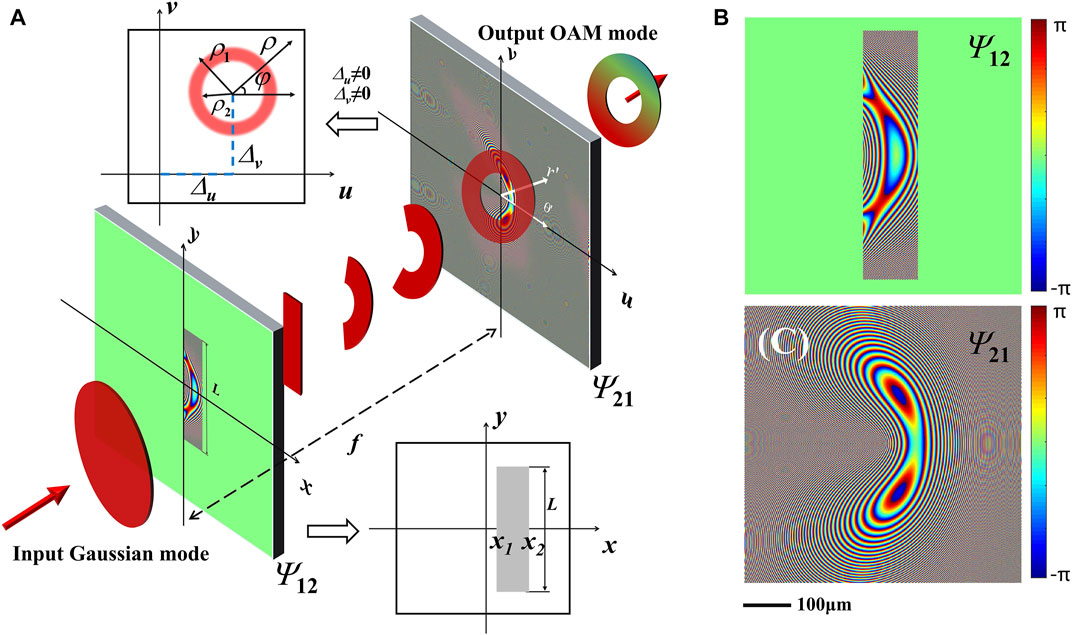
FIGURE 1. Vortex beam generation via geometric coordinate transformation (GCT). (A) Schematic of the coordinate transformation from a rectangular beam to a ring-shaped one. (B,C) Typical transforming (Ψ12) and correcting (Ψ21) phases.
Assuming that the incident light field in the rectangular region in the input plane (x, y) would take part in the GTC, the rectangular function of this region can be expressed as:
where, x1, x2, L are to depict the range of the rectangular region.
After modulated by the transforming phase, the light field in the rectangular region curls up into an annular beam on the output plane (u, v). We suppose that the center of the annular beam is located at (Δu, Δv), and the outer and inner radii of the annular are ρ1, ρ2, respectively. Considering that the beam follows the paraxial propagation, and the coordinate transformation needs to satisfy a sufficient but not necessary condition if ∂2Ψ12 (x1,y1)/∂x1∂y1 and ∂2Ψ12 (x1,y1)/∂y1∂x1 exist and are continuous: ∂u/∂y = ∂v/∂x and ∂x/∂v = ∂y/∂u [17], the coordinate mapping relationship can be written as follows:
where, a = L/2π determines the length of the rectangular region; b = x1,2/exp (-ρ1,2/a), determines the ratio of the width of the rectangle and the ring width; Δu and Δv denote the offset distance of the annular beam in the direction of u and v axis, respectively; (ρ, φ) are the polar coordinates in the output plane with the origin set at (Δu, Δv), and meet
As shown in Figure 1A, when Δu, Δv is not 0, the generated vortex beam will be shifted from the origin. The GTC must satisfy the following phase-solving conditions:
where, k = 2π/λ is the wavenumber, λ is the wavelength of the incident light, and f is the spacing between the two phase elements. By solving Eq. (5), the analytical expressions of the transforming and correcting phases are obtained as follows:
Figure 1B and Figure 1C represent the typical distributions of the transforming and correcting phases, respectively. Considering that only the incident light field in the rectangular region is needed, the transmission function of the incident plane should be restriced by a rectangular aperture function, expressed as t (x, y) = Θ(x, y)exp (iΨ12).
When an incident beam with a phase gradient in the y axis, expressed as U (x,y)exp (ikyy), is input (Figure 1A), it will gradually curl up from a rectangle to a ring. To generate the ℓth-order spiral phase exp (iℓφ), it is necessary to make the incident phase gradient satisfy ky = ℓ/a according to Eq. (3). It can be concluded that by adjusting the phase gradient of the incident beam, a vortex beam with adjustable TC would be generated.
Results and analysis
We numerically simulate the above method of generating the vortex beam by choosing the following parameters: λ = 632.8nm, f = 175mm, Δu = Δv = 0, a = 1mm, b = 2 mm. The inner and outer radii of the annular beam to be generated are determined by taking ρ2 = 0.5 mm and ρ1 = 2mm, and then the rectangular function Θ(x, y) is calculated by substituting L = 2πa and x1,2 = b exp (-ρ1,2/a) into Eq. (1). To meet the experimental conditions, the incident light field is taken as a Gaussian beam, i.e., U (x, y) = exp [-(x2+y2)/w2], with waist radius w = 8 mm. The incident field U (x,y)exp (ikyy) is attached to the transforming phase Ψ12 and then propagates the distance f, where the diffraction field can be calculated by the Fresnel diffraction integral. Finally, the diffraction field is corrected by multiplying by the phase exp (iΨ21), and forms the output annular beam. The propagation process of the incident Gaussian beam is shown in Figure 2, where Figures 2A–F give the intensity distributions at different distances. The dashed line in Figure 2A marks the rectangular transmission area of the incident plane, and the dashed circles in Figure 2F mark the range of the predesigned output. From these results, we can clearly see: the rectangular beam gradually bends into an arc firstly, and tends to converge to a thin line (Figures 2B–D); thereafter, it bends further and gradually diverges to an annular beam (Figures 2E,F). The inner and outer radii of the resulting ring beam are basically in line with the preset values. It should be noted that, because the mapping of the coordinateis is nonlinear [ρ1,2 = bexp (-x1,2/a)], the intensity distribution of the resulting annular beam is not uniform, but declines as the radial location increases. Notablely, the nonuniform intensity distribution over the rectangular area would make the resulting annular beam axis-asymmetric. But hard-edge diffraction of the rectangular field has an even bigger effect. Thus, the input intensity distribution will not affect the purity of the OAM state too much.
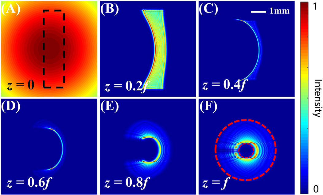
FIGURE 2. Propagation process for the GCT. (A) Input Gaussian beam, with the transmission area marked by the dashed rectangle. (B–F) Intensity distributions at different propagation distances.
By setting the TC ℓ = 3, 5, 8, 10, and 15, the phase gradient exp (iℓy/a) is attached to the input beam, and the simulation results are shown in Figure 3, where Figure 3A and Figure 3B depict the intensity and phase distributions, resepectively. Notably, the intensity distributions of the resulting beams are almost identical, indicating that the phase variation of the incident beam has no significant effect on the GTC. While from the phase patterns, it can be clearly seen that the typical spiral phases are formed: the phases changes 2πℓ around the center. It indicates that vortex beams with TC of ℓ are generated.
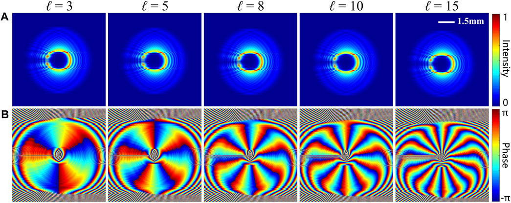
FIGURE 3. Intensity (A) and phase (B) distribution of the generated vortex beams by setting the topological charge ℓ = 3, 5, 8, 10, and 15.
The purity of the resulting integer-order vortex beam can be analyzsed with the Fourier relationship between the OAM spectrum [24]. For example, the OAM spectrum expansion is performed for the generated vortex beam with TC ℓ = 3, and the normalized percentage of each OAM component occupied is calculated. The result between the interval [-7, 13] is shown in Figure 4A. It can be seen that the OAM component with ℓ = 3 accounts for about 90% of the generated vortex beam, indicating the hight purity of the generated vortex beam and the high efficiency of the mode conversion. In order to analyse the purity of the resulting vortex beam with different TC, we calculate the OAM spectra by taking ℓ from -15 to 15, and extracting the corresponding OAM mode purity as shown in Figure 4B. It is obvious that the vortex conversion efficiency for the TC of |ℓ| becomes progressively lower as |ℓ| increases. This indicates that this method would be not so efficient for generating higher-order vortex beams. The conversion efficiency can be maintained at around 90% for ℓ between -5 and 5. However, as |ℓ| increases more, the conversion efficiency decreases significantly. Nevertheless, the efficiency can be guaranteed to be above 50% for the resulting beams with the absolute values of TCs less than 10.
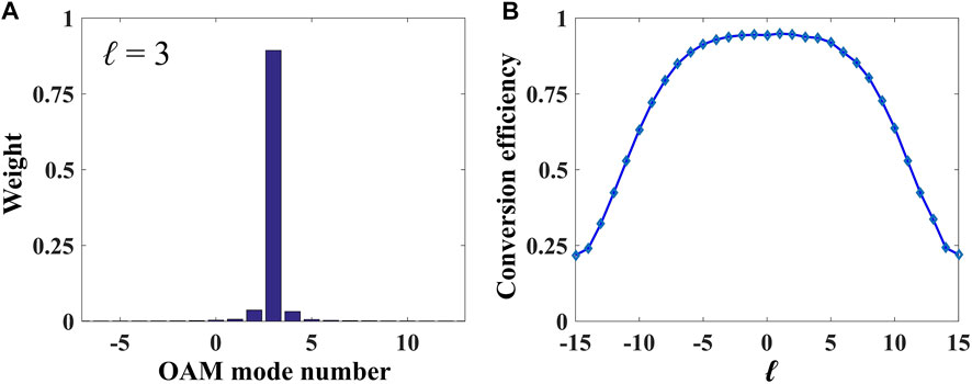
FIGURE 4. Purity of the generated vortex beams. (A) The OAM spectrum of output beam with ℓ = 3. (B) Conversion efficiency of vortex beam versus ℓ.
For the phase gradient exp (iℓy/a) attached to the input beam, ℓ can be chosen as not only an integer. When the phase gradient is changed continuously, ℓ is more likely to be a fraction. Thus, a fraction-order vortex beam can be generated for a non-integral ℓ. By changing ℓ as a fraction between 4 and 5, we generate the vortex beams with GCT, and the results are shown in Figure 5. Figures 5A–D show the phase distributions of the resulting beams. It is hardly to directly estimate the TC of these non-integer-order spiral phases. We extract the phase distributions at a circle of radius 1 mm in the phase patterns as shown in Figures 5A–D, and compare with the phases of the standard fractional-order vortex beams. The results are given in Figures 5E–H, where the blue and red curves correspond to the simulation and theoretical results, respectively. As can be seen, for an integral TC, the phase is continuous at -π and π (Figure 5E); while for a fractional TC, an obvious phase jump occurs at -π and π. More strikingly, the phases for the simulated results highly coincide with the theoretical ones except for some noisy points due to the edge diffraction of the light field (Figures 5F–H). Figures 5I–L show the corresponding comparations of the OAM spectra between the simulation and theoretical results. It can be seen that the fraction-order vortex beams no longer occupy a single OAM, but also has other OAM components. As ℓ approaches 4, the OAM modes with TC of 4 prevails; as ℓ approaches 5, the OAM modes with TC of 5 dominate the OAM spectrum. The simulation results are in general agreement with the theoretical ones, except that the dominant OAM components are slightly lower because the conversion efficiency of the vortex beam in this method cannot be 100%.
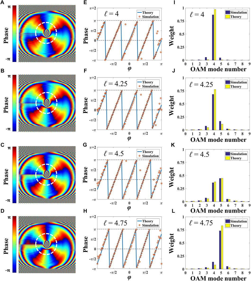
FIGURE 5. Properties of the generated fraction-order vortices. (A–D) Phase distributions. (E–H) Phase variations along with the circles in (A–D). (I–L) OAM spectrum corresponding to (A–D).
The transverse position and spot size of the resulting vortex beam can be controlled by varying the parameters Δu, Δv, and b, as shown in Figure 6. By setting Δu = -Δv = 1.5mm, and Δu = 1.5mm, Δv = 0, the position control of the vortex beam is realized as shown in Figures 6A–D, where Figures 6A,B, and Figures 6C,D correspond to the intensity and phase distributions, respectively. Figures 6A,C, and Figures 6B,D obviously reveal that the resulting vortex beams are shifted along the vectors (1.5mm, -1.5 mm) and (1.5mm, 0), respectively. Here, the parameters Δu, Δv are taken into account in the coordinate mapping relationship, due to the consideration of the corresponding follow-up study under most experimental conditions. Since the phase modulation of an light field always has errors in experiments, the zero-order diffraction spot, which locates on the center of the coordinates, is hard to be eliminated. By attaching the parameters Δu, Δv to the phase, the resulting beam is moved far from the zero-order spot, which can be filtered out. Another consideration is the spot size. A resulting beam with a large size might overlap with the zero-order spot, which would be adverse to the beam filtering. Thus, it is important to control the spot size in theoretical pre-research. Figures 6E–H represent the intensity and phase distributions of the vortex beams produced at different radii for b = 3 and 1mm, respectively. As can be seen, the size of the resulting vortex beam is adjustable by varying the parameter b.
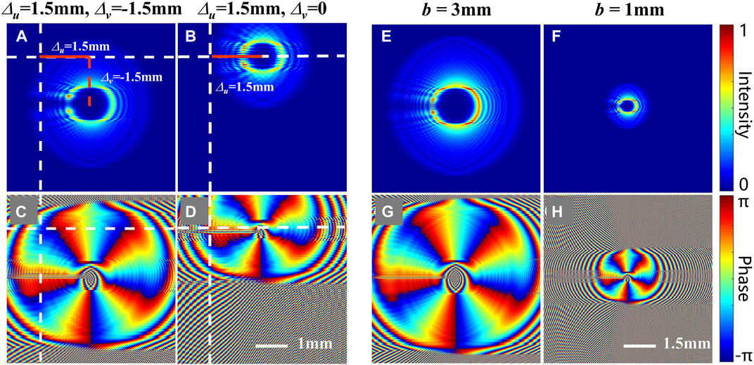
FIGURE 6. Control of the transverse position (A–D) and spot size (E–H) of the vortex beam. The top and bottom correspond to the intensity and phase distributions.
In addition, considering that the phase alignment is also an unavoidable problem in the experiment, the influence of the misalignment of the phase elements is analyzed below. There are two main cases of phase misalignment as shown in Figure 7A: the axial offset (ΔF) and the lateral offset (ΔC). By choosing ℓ = −9, −5, 1, and 4, we calculate the conversion efficiency of the OAM mode versus the axial and lateral offsets, as shown in Figure 7B and Figure 7C, respectively. From these results, it can be seen that the conversion efficiency of the OAM mode is basically normally distributed with the offsets. The position deviation of the correcting phase element, along with whether axial or lateral directions, would cause a rapid reduction of the efficiency of the resulting vortex beam. More importantly, the efficiency reduction is much more sensitive to the lateral offset. For the axial offset, the conversion efficiency of the 9 order vortex beam drops to about 50% when the offset is increased to10 mm. While for the lateral offset, the efficiency decreases rapidly to 20% once the offset exceeds 10 μm. In a word, the correcting phase needs more precise lateral alignment, while permitting the axial alignment in a larger tolerance range.

FIGURE 7. Effect of phase alignment. (A) Schematic of the axial and lateral offsets. (B,C) The conversion efficiency of the vortex beam vs. offset.
Conclusion
Based on the theory of GCTs, a method is proposed to generate the vortex beam, of which the TC can be adjusted by varying the phase gradient of the incident beam. The Cartesian to log-polar coordinate transformation is performed to achieve a conformal mapping from a rectangular beam to a ring-shaped one. By attached with a variable phase gradient, an input rectangular beam can curl up to an annular beam, and its phase eloves into a spiral one. In contrast to the previous research results, the advantage of this method is that the TC of the generated vortex beam is continuously tunable. Vortex beams with integer-order and fraction-order TCs are obtained by using this method. Based on the OAM spectrum, the purity of the generated vortex beam is analyzed, as well the possible effects of phase misalignment on the output vortex. The results show that the conversion efficiency would be gradually reduced with the increasing of TC of the generated vortex beam. In addition, it reveals that the correcting phase needs more precise lateral alignment, while permitting the axial alignment in a larger tolerance range. The proposed continuously tunable vortex beam is expected to be used in the information processing and the optical routing in optical communications.
Data availability statement
The original contributions presented in the study are included in the article/Supplementary Material, further inquiries can be directed to the corresponding authors.
Author contributions
SL, PL, BW, and JZ were responsible for the conceptualization of the study; Sheng Liu, Yanke Li, and YX wrote the draft. All authors were involved in the revision and agreed to be accountable for the content of the article.
Funding
National Key Research and Development Program of China (2017YFA0303800); National Natural Science Foundation of China (12074312, 11634010, 12174309, 12074313); Fundamental Research Funds for the Central Universities (3102019JC008).
Conflict of interest
The authors declare that the research was conducted in the absence of any commercial or financial relationships that could be construed as a potential conflict of interest.
Publisher’s note
All claims expressed in this article are solely those of the authors and do not necessarily represent those of their affiliated organizations, or those of the publisher, the editors and the reviewers. Any product that may be evaluated in this article, or claim that may be made by its manufacturer, is not guaranteed or endorsed by the publisher.
References
1. Allen L, Beijersbergen MW, Spreeuw RJC, Woerdman JP. Orbital angular momentum of light and the transformation of Laguerre-Gaussian laser modes. Phys Rev A (1992) 45:8185–9. doi:10.1103/physreva.45.8185
2. Zhong J, Liu S, Guo X, Li P, Wei B, Han L, et al. Observation of optical vortex knots and links associated with topological charge. Opt Express (2021) 29:38849. doi:10.1364/OE.441263
3. Zhong J, Liu S, Wang K, Li P, Wei B, Guo X, et al. Poincaré sphere analogue for optical vortex knots. Opt Lett (2022) 47:313. doi:10.1364/OL.448783
4. Simpson NB, Allen L, Padgett MJ Optical tweezers and optical spanners with Laguerre-Gaussian modes. J Mod Opt (1996) 43:2485–91. doi:10.1080/09500349608230675
5. Paterson L, MacDonald MP, Arlt J, Sibbett W, Bryant PE, Dholakia K, et al. Controlled rotation of optically trapped microscopic particles. Science (2001) 292:912–4. doi:10.1126/science.1058591
6. MacDonald MP, Lynn P, Volke-Sepulveda K, Arlt J, Sibbett W, Dholakia K, et al. Creation and manipulation of three-dimensional optically trapped structures. Science (2002) 296:1101–3. doi:10.1126/science.1069571
7. Tamburini F, Anzolin G, Umbriaco G, Bianchini A, Barbieri C Overcoming the Rayleigh criterion limit with optical vortices. Phys Rev Lett (2006) 97:163903. doi:10.1103/PhysRevLett.97.163903
8. Bozinovic N, Yue Y, Ren Y, Tur M, Kristensen P, Huang H, et al. Terabit-scale orbital angular momentum mode division multiplexing in fibers. Science (2013) 340:1545–8. doi:10.1126/science.1237861
9. Mafu M, Angela D, Sandeep G, Daniel G, Melanie M, Miles JP, et al. Higher-dimensional orbital-angular-momentum-based quantum key distribution with mutually unbiased bases. Phys Rev A (2013) 88:032305. doi:10.1103/PhysRevA.88.032305
10. Wang J, Yang JY, Fazal IM, Ahmed N, Yan Y, Huang H, et al. Terabit free-space data transmission employing orbital angular momentum multiplexing. Nat Photon (2012) 6:488–96. doi:10.1038/nphoton.2012.138
11. Beijersbergen MW, Allen L, Veen HELOvan der, Woerdman JP Astigmatic laser mode converters and transfer of orbital angular momentum. Opt Commun (1993) 96:123–32. doi:10.1016/0030-4018(93)90535-D
12. Massari M, Ruffato G, Gintoli M, Ricci F, Romanato F Fabrication and characterization of high-quality spiral phase plates for optical applications. Appl Opt (2015) 54:4077. doi:10.1364/AO.54.004077
13. Heckenberg NR, McDuff R, Smith CP, White AG. Generation of optical phase singularities by computer-generated holograms. Opt Lett (1992) 17:221. doi:10.1364/OL.17.000221
14. Wei BY, Hu W, Ming Y, Xu F, Rubin S, Wang JG, et al. Generating switchable and reconfigurable optical vortices via photopatterning of liquid crystals. Adv Mater (2014) 26:1590–5. doi:10.1002/adma.201305198
15. Dorrah AH, Rubin NA, Tamagnone M, Zaidi A, Capasso F. Structuring total angular momentum of light along the propagation direction with polarization-controlled meta-optics. Nat Commun (2021) 12:6249. doi:10.1038/s41467-021-26253-4
16. Bernet S, Monika R. Adjustable refractive power from diffractive moire elements. Appl Opt (2008) 47:3722. doi:10.1364/AO.47.003722
17. Hossack WJ, Darling AM, Dahdouh A. Coordinate transformations with multiple computer-generated optical elements. J Mod Opt (1987) 34:1235–50. doi:10.1080/09500348714551121
18. Berkhout GCG, Lavery MPJ, Courtial J, BeijersbergenPadgett MWMJ. Efficient sorting of orbital angular momentum states of light. Phys Rev Lett (2010) 105:153601. doi:10.1103/PhysRevLett.105.153601
19. Mirhosseini M, Malik M, Shi Z, Boyd RW. Efficient separation of the orbital angular momentum eigenstates of light. Nat Commun (2013) 4:2781. doi:10.1038/ncomms3781
20. Wen Y, Chremmos I, Chen Y, Zhu J, Zhang Y, Yu S, et al. Spiral transformation for high-resolution and efficient sorting of optical vortex modes. Phys Rev Lett (2018) 120:193904. doi:10.1103/PhysRevLett.120.193904
21. Ruffato G, Massari M, Romanato F. Multiplication and division of the orbital angular momentum of light with diffractive transformation optics. Light Sci Appl (2019) 8:113. doi:10.1038/s41377-019-0222-2
22. Wen Y, Chremmos I, Chen Y, Zhang Y, Yu S. Arbitrary multiplication and division of the orbital angular momentum of light. Phys Rev Lett (2020) 124:213901. doi:10.1103/PhysRevLett.124.213901
23. Willner AE, Li L, Xie G, Ren Y, Huang H, Yue Y, et al. Orbital-angular-momentum-based reconfigurable optical switching and routing. Photon Res (2016) 4:5. doi:10.1364/prj.4.0000b5
Keywords: geometric coordinate transform, vortex beam, orbital angular momentum, fractional-order vortex, information codes
Citation: Li Y, Xie Y, Liu S, Li P, Wei B and Zhao J (2022) Theoretical study of vortex beam generation based on geometric coordinate transformation. Front. Phys. 10:898638. doi: 10.3389/fphy.2022.898638
Received: 17 March 2022; Accepted: 06 July 2022;
Published: 25 July 2022.
Edited by:
Gianluca Ruffato, University of Padua, ItalyReviewed by:
Siyuan Yu, Sun Yat-sen University, ChinaWeiren Zhu, Shanghai Jiao Tong University, China
Copyright © 2022 Li, Xie, Liu, Li, Wei and Zhao. This is an open-access article distributed under the terms of the Creative Commons Attribution License (CC BY). The use, distribution or reproduction in other forums is permitted, provided the original author(s) and the copyright owner(s) are credited and that the original publication in this journal is cited, in accordance with accepted academic practice. No use, distribution or reproduction is permitted which does not comply with these terms.
*Correspondence: Sheng Liu, c2hlbmdsaXVAbndwdS5lZHUuY24=; Peng Li, cGVuZ2xpQG53cHUuZWR1LmNu
†These authors have contributed equally to this work and share first authorship
 Yanke Li
 Yuqing Xie†
 Sheng Liu
 Peng Li
 Bingyan Wei
 Jianlin Zhao