- School of Optoelectronic Engineering, Xi’an Technological University, Xi’an, China
Camera calibration plays an important role in various applications including machine vision and optical measurement. In this paper, we propose a new calibration method of stereo line-scan cameras for 2D coordinate measurement using a simple calibration target rather than requiring complex calibration patterns or an auxiliary area-scan camera. Considering the viewing planes associated with the stereo line-scan cameras are coplanar, an imaging model combining perspective projection and lens distortion are established and can depict the relationship between the 2D world coordinate and its corresponding 1D pixel coordinates of the image pairs. A two-step calibration algorithm is proposed to obtain the optimal values of intrinsic, extrinsic and distortion parameters of stereo line-scan cameras. The performance of the proposed camera calibration method is evaluated on 2D coordinate measurement and the experimental results demonstrate that the proposed method is more effective and accurate than the existing method.
Introduction
Line-scan (also called linear or 1D) cameras are becoming widely used to various applications including machine vision and optical measurement, such as agricultural robot navigation [1], railway catenary inspection [2], surface defect detection [3], 2D coordinate measurement [4] and 3D shape measurement [5–7]. There are two types of line-scan cameras: single-line camera and multiline camera [8], which can be considered as a particular area-scan (also called matrix or 2D) camera consisting of a single row or multiple rows of pixel elements [9]. Compared with area-scan cameras, line-scan cameras can provide higher spatial resolution, higher imaging rates (up to 16384 pixels at 300 kHz) and lower manufacturing cost [9, 10].
In the camera-based applications, camera calibration plays an important role and is a necessary step in order to extract metric information from 2D images [8, 11]. The key of calibration is to find out the initial values of intrinsic and extrinsic camera parameters, which demonstrate the mapping relationship between the 2D coordinates in the image and the 3D coordinates in the object world [12] and will be refined by a non-linear optimization technique to obtain more accurate calibration parameters. Conventional calibration methods for area-scan cameras [11, 13] are not applicable to the line-scan cameras because of their different imaging principles [8]. For line-scan cameras, the calibration process is more complicated and several calibration methods have been presented in the last decades. The authors have performed the investigation and reviewed on line-scan camera calibration methods [9]. Generally, these methods can be classified into two groups: static imaging calibration and dynamic imaging calibration [8, 14].
Static imaging calibration employs the patterns on the calibration target comprising several feature lines. The 3D coordinates of intersection points that can be found by solving the viewing plane equation of the line-scan camera and the feature lines equations are applied for calibration. It is worth noting that each row data of the captured image is almost the same because there is no relative motion between the camera and the calibration target. Horaud et al. [15] proposed a multiline calibration method where cross-ratio invariance is used to compute the intersection points. However, it is necessary to move the calibration target along the
Dynamic imaging calibration estimates the line-scan camera parameters by a series of scanning operations. More generally, a linear relative motion with constant velocity between the camera and the calibration target is typically considered. Draréni et al. [23] utilized a controllable linear stage to translate the line-scan camera along the
As for the stereo line-scan cameras, 2D coordinates or 3D shape can be calculated by the well-known triangulation method when they are properly calibrated. A few stereo line-scan camera systems for industrial applications have been reported in the literature. Ma et al. [4] presented a 2D coordinate measurement system based on stereo line-scan cameras which are calibrated by using several rods perpendicular to a flat plate at some special locations. The calibration is easy to implement due to its simple target, but its major defects are quite obvious: time consuming and low accuracy caused by occlusion imaging. Sun et al. [5] developed a high-speed 3D shape measurement system for moving objects. The stereo line-scan cameras can be calibrated by their static imaging calibration method [22] or [6]. Lilienblum et al. [29] extended the calibration method [17] for 3D measurement system consisting of stereo line-scan cameras. Zhan et al. [2] proposed an accurate and efficient measurement approach for railway catenary geometry parameters by using stereo line-scan cameras. Liao et al. [7] gave a dense 3D point cloud measurement system comprising dual line-scan cameras and a matching strategy to expand the depth measurement range. Most recently, Steger and Ulrich [30] introduced their line-scan camera model [28] to the multi-view case with an arbitrary number of cameras for 3D surface reconstruction.
In this paper, based on the work of Ma et al. [4] and our previous work [9], we propose a new calibration method of stereo line-scan cameras for 2D coordinate measurement. The rest of this paper is organized as follows. In section 2, we establish an imaging model of stereo line-scan cameras that serves as the basis for our method. In section 3, the proposed calibration method for intrinsic, extrinsic and distortion parameters is described in detail. Experimental results on 2D coordinate measurement are performed and discussed in section 4. Finally, we conclude our method in section 5.
Our main contributions are summarized as follows:
1) We propose a static imaging calibration method of stereo line-scan cameras using a simple calibration target. Complex calibration patterns/targets are not required to calibrate cameras; auxiliary imaging devices, such as area-scan camera, do not need to aid the calibration.
2) We establish an imaging model for stereo line-scan cameras that are coplanar aligned. Lens distortion is taken into consideration to improve the model performance.
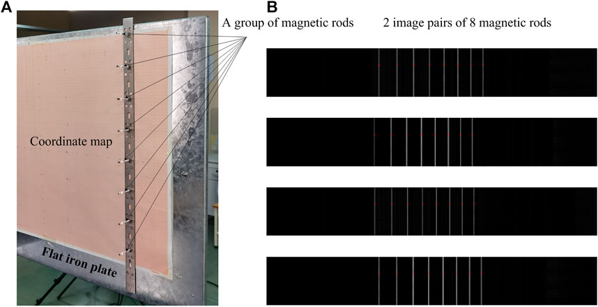
3) We design a calibration target with simple structure and low cost. The target comprises a group of magnetic rods perpendicular to a flat iron plate with a coordinate map which can give the world coordinates.
4) The time required for the calibration process is greatly reduced with the help of the simple target, translation and a two-step algorithm that determines the camera parameters using the images of a group of rods.
Imaging Model of Stereo Line-Scan Cameras
Stereo Line-Scan Camera System
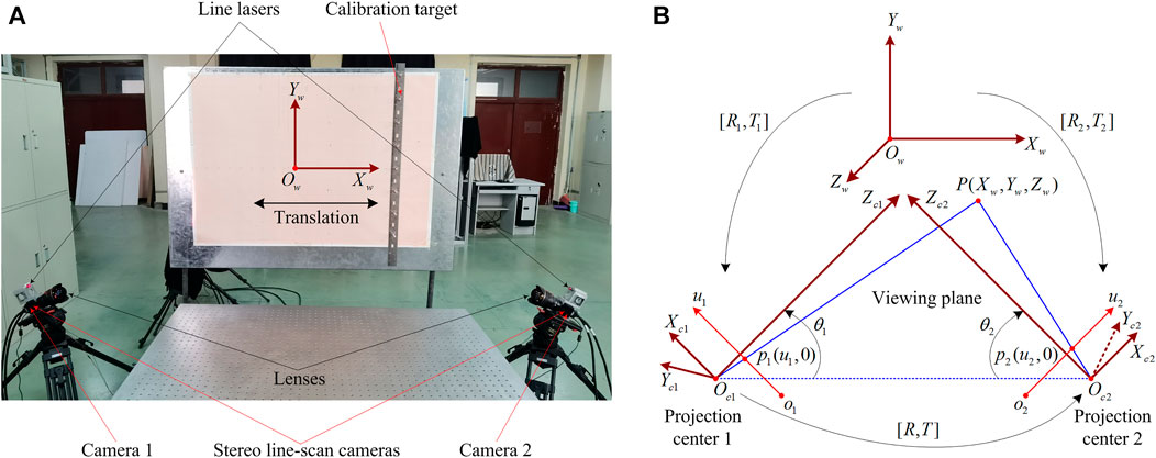
The stereo line-scan camera system has various arrangement modes [7]. For our system, the side-by-side mode is chosen. As depicted in Figure 1A, the system mainly includes two line-scan cameras (Dalsa, spL2048-140km) mounted lens (Nikon, AF Nikkor 14 mm f/2.8D), two line lasers, a industrial computer with two frame grabbers (Dalsa, OR-X4C0-XPF00), several mechanical and calibration devices. Like most stereo line-scan camera systems [2, 4–7, 29], our system also requires the two line-scan cameras to be coplanar aligned manually using a suitable mechanical device so that the two viewing planes determined by the projection center and the pixel elements are approximately coplanar. Consequently, the measurement field is the overlapping area of the two planes.

FIGURE 1. Stereo line-scan camera system and imaging model. (A) Stereo line-scan camera system and (B) Imaging model of stereo line-scan cameras.
Imaging Model
It is necessary for an imaging model to define the coordinate systems in order to describe the intrinsic and extrinsic parameters. As shown in Figure 1B, the world coordinate system, the two camera coordinate systems and the two pixel coordinate systems are denoted by
For the line-scan camera, perspective projection is only satisfied along the pixel elements direction, i.e.,
where
Because a world point
where
Taking Eq. 2 into Eq. 1, we can get
By substituting the second equation into the first equation of (3) and substituting the fourth equation into the third equation of (3), Eq. 3 can be transformed into the following descriptions
Obviously, the imaging model (3) or (4) can depict the relationship between the 2D world coordinate
Lens Distortion Model
It is easy to see that the imaging model (3) or (4) is linear. However, the actual imaging is a nonlinear process inevitably affected by different kinds of lens distortions [2]. To improve the model performance and measurement accuracy, lens distortion is taken into consideration.
For the area-scan cameras, the mathematical expressions for three types of lens distortions are as follows [9, 31].
where
Considering the specialty of line-scan camera [32],
If we ignore the third radial distortion and set
Considering the lens distortion, Eq. 1 can be rewritten as
Substituting Eq. 8 into Eq. 4, we can derive the real distorted imaging model
Calibration Method
Calibration Target
As shown in Figure 2A, our designed calibration target comprises a group of magnetic rods (8 collinear feature points with 100 mm spacing) perpendicular to a flat iron plate. The plate is adjusted to be parallel to the viewing plane and pasted by a coordinate map which can give the 2D world coordinates

FIGURE 2. Calibration target and sub-pixel location. (A) Calibration target with a group of magnetic rods (B) Sub-pixel locations of rod centers in the image pairs.
Computing the Initial Values
A two-step algorithm is proposed to determine the optimal values of intrinsic, extrinsic and distortion parameters. Firstly, we will compute the initial values of intrinsic and extrinsic camera parameters by solving the imaging model (4) with given feature points. Secondly, the initial values will be refined by a non-linear optimization technique to greatly improve the calibration accuracy.
Given
with
where
The matrix
Solving this equation, the intrinsic and extrinsic parameters can be obtained
Obviously, according to the coordinate systems defined in Figure 1B, we can get
Non-linear Optimization
In the initial calculation of the parameters, the distortion is neglected. In order to obtain more accurate calibration parameters, a non-linear optimization technique such as Levenberg-Marquardt algorithm is employed to refine the camera parameters. The goal is to find out the optimal intrinsic, extrinsic and distortion parameters which minimize the sum of squares of reprojection errors, i.e.,
where
Once the parameters of two line-scan cameras are respectively refined, we can furthermore minimize the sum of squares of reprojection errors for each camera, i.e.,
to obtain the final accurate parameters of stereo line-scan cameras, where the initial values of
Experimental Results and Discussion
Calibration Experiment
To evaluate the effectiveness of the proposed method, we calibrate our stereo line-scan camera system. It can be observed from Figures 1A and 2A, when the calibration target is translated on the flat plate, the coordinate map can give the 2D world coordinates
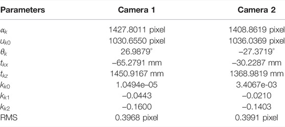
Table 1 shows the calibration results of stereo line-scan cameras. We implement our method in Matlab. The root mean square (RMS) of reprojection errors of two camera is less than 0.40 pixel. It is well mentioning that the time of our calibration process is no more than 5 min for both cameras while the time of the method [4] for each camera is about 30 min. The time required for our calibration process is greatly reduced mainly due to the help of the simple target and simple translation operation. Therefore it can be said that our proposed method is significantly effective.
2D Coordinate Measurement
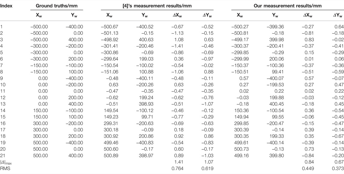
Furthermore, our calibration parameters are verified by measuring the 2D coordinates in the measurement field with a range of
The 2D coordinates can be triangulated by solving Eq. 4, then
where
A comparison between our and [4]’s measurement results is shown in Table 2. We test a total of 21 2D points similar to [4]. According to the results, it can be seen obviously that the maximum errors of our method for
In conclusion, the experimental results demonstrate that our proposed method can provide satisfactory 2D coordinate measurement and has much more superiority both in the calibration time and accuracy compared with the [4]’s method.
Conclusion
We have proposed a calibration method for the stereo line-scan camera system. We firstly established the real distorted imaging model by combining a perspective projection and three types of lens distortions. On the basis of the model which can depict the relationship between the 2D world coordinate and its corresponding 1D pixel coordinates of the image pairs, we have proposed a two-step algorithm to find out the optimal parameters of stereo line-scan cameras. The initial values of intrinsic and extrinsic parameters were computed by solving the system of homogeneous equations derived by the image model and feature points. We employed the Levenberg-Marquardt optimization algorithm to refine the intrinsic, extrinsic and distortion parameters by minimizing the reprojection errors. Finally, the experimental results verified that our proposed method can provide satisfactory 2D coordinate measurement with less calibration time and a higher accuracy. Further study of line-scan camera calibration includes the flexible calibration target and non-coplanar alignment.
Data Availability Statement
The original contributions presented in the study are included in the article/Supplementary Material, further inquiries can be directed to the corresponding author.
Author Contributions
All authors contributed to the research work. GW proposed the method and designed the experiments; LZ and HZ performed the experiments and analyzed the data; GW wrote the manuscript.
Funding
This research is funded by Natural Science Basic Research Program of Shaanxi (Program No. 2022JM-318) and Comprehensive Reform Research and Practice Project of Graduate Education in Shaanxi Province (Program No. YJSZG2020074).
Conflict of Interest
The authors declare that the research was conducted in the absence of any commercial or financial relationships that could be construed as a potential conflict of interest.
Publisher’s Note
All claims expressed in this article are solely those of the authors and do not necessarily represent those of their affiliated organizations, or those of the publisher, the editors and the reviewers. Any product that may be evaluated in this article, or claim that may be made by its manufacturer, is not guaranteed or endorsed by the publisher.
Acknowledgments
The work is partly done during the first author’s visit at Nanyang Technological University, Singapore, with a support by Kemao Qian. We gratefully acknowledge Dr. Kemao Qian for his very valuable help. We would also like to thank the reviewers for the valuable and constructive comments that helped us improve the presentation.
References
1. Su D, Bender A, Sukkarieh S. Improved Cross-Ratio Invariant-Based Intrinsic Calibration of A Hyperspectral Line-Scan Camera. Sensors (2018) 18:1885. doi:10.3390/s18061885
2. Zhan D, Jing D, Wu M, Zhang D, Yu L, Chen T. An Accurate and Efficient Vision Measurement Approach for Railway Catenary Geometry Parameters. IEEE Trans Instrum Meas (2018) 67:2841–53. doi:10.1109/TIM.2018.2830862
3. Liu Z, Wu S, Wu Q, Quan C, Ren Y. A Novel Stereo Vision Measurement System Using Both Line Scan Camera and Frame Camera. IEEE Trans Instrum Meas (2019) 68:3563–75. doi:10.1109/TIM.2018.2880080
4. Ma W, Dong T, Tian H, Ni J. Line-Scan CCD Camera Calibration in 2D Coordinate Measurement. Optik (2014) 125:4795–8. doi:10.1016/j.ijleo.2014.04.057
5. Sun B, Zhu J, Yang L, Yang S, Guo Y. Sensor for In-Motion Continuous 3D Shape Measurement Based on Dual Line-Scan Cameras. Sensors (2016) 16:1949. doi:10.3390/s16111949
6. Sun B, Zhu J, Yang L, Guo Y, Lin J. Stereo Line-Scan Sensor Calibration for 3D Shape Measurement. Appl Opt (2017) 56:7905–14. doi:10.1364/AO.56.007905
7. Liao R, Yang L, Ma L, Yang J, Zhu J. A Dense 3-D Point Cloud Measurement Based on 1-D Background-Normalized Fourier Transform. IEEE Trans Instrum Meas (2021) 70:5014412. doi:10.1109/TIM.2021.3075740
8. Yuan G, Zheng L, Ding Y, Zhang H, Zhang X, Liu X, et al. A Precise Calibration Method for Line Scan Cameras. IEEE Trans Instrum Meas (2021) 70:5013709. doi:10.1109/TIM.2021.3090157
9. Wang G, Qian K. Review on Line-Scan Camera Calibration Methods. Acta Optica Sinica (2020) 40:0111011. doi:10.3788/AOS202040.0111011
10. Li D, Wen G, Qiu S. Cross-Ratio-Based Line Scan Camera Calibration Using A Planar Pattern. Opt Eng (2016) 55:014104. doi:10.1117/1.OE.55.1.014104
11. Zhang Z. A Flexible New Technique for Camera Calibration. IEEE Trans Pattern Anal Machine Intell (2000) 22:1330–4. doi:10.1109/34.888718
12. Wang G, Zheng H, Zhang X. A Robust Checkerboard Corner Detection Method for Camera Calibration Based on Improved YOLOX. Front Phys (2022) 9:819019. doi:10.3389/fphy.2021.819019
13. Abdel-Aziz YI, Karara HM. Direct Linear Transformation from Comparator Coordinates into Object Space Coordinates in Close-Range Photogrammetry. Photogramm Eng Remote Sensing (2015) 81:103–7. doi:10.14358/PERS.81.2.103
14. Liao R, Zhu J, Yang L, Lin J, Sun B, Yang J. Flexible Calibration Method for Line-Scan Cameras Using A Stereo Target with Hollow Stripes. Opt Lasers Eng (2019) 113:6–13. doi:10.1016/j.optlaseng.2018.09.014
15. Horaud R, Mohr R, Lorecki B. On Single-Scanline Camera Calibration. IEEE Trans Robot Automat (1993) 9:71–5. doi:10.1109/70.210796
16. Luna CA, Mazo M, Lázaro JL, Vázquez JF. Calibration of Line-Scan Cameras. IEEE Trans Instrum Meas (2010) 59:2185–90. doi:10.1109/TIM.2009.2031344
17. Lilienblum E, Al-Hamadi A, Michaelis B. A Coded 3d Calibration Method for Line-Scan Cameras. In: J Weickert, M Hein, and B Schiele, editors. Proceedings of the 35th German Conference on Pattern Recognition. Berlin, Heidelberg: Springer (2013). p. 81–90. doi:10.1007/978-3-642-40602-7_9
18. Li D, Wen G, Hui BW, Qiu S, Wang W. Cross-Ratio Invariant Based Line Scan Camera Geometric Calibration with Static Linear Data. Opt Lasers Eng (2014) 62:119–25. doi:10.1016/j.optlaseng.2014.03.004
19. Song K, Hou B, Niu M, Wen X, Yan Y. Flexible Line-Scan Camera Calibration Method Using A Coded Eight Trigrams Pattern. Opt Lasers Eng (2018) 110:296–307. doi:10.1016/j.optlaseng.2018.06.014
20. Niu M, Song K, Wen X, Zhang D, Yan Y. The Line Scan Camera Calibration Based on Space Rings Group. IEEE Access (2018) 6:23711–21. doi:10.1109/ACCESS.2018.2817629
21. Yao M, Zhao Z, Xu B. Geometric Calibration of Line-Scan Camera Using a Planar Pattern. J Electron Imaging (2014) 23:013028. doi:10.1117/1.JEI.23.1.013028
22. Sun B, Zhu J, Yang L, Yang S, Niu Z. Calibration of Line-Scan Cameras for Precision Measurement. Appl Opt (2016) 55:6836–43. doi:10.1364/AO.55.006836
23. Draréni J, Roy S, Sturm P. Plane-Based Calibration for Linear Cameras. Int J Comput Vis (2011) 91:146–56. doi:10.1007/s11263-010-0349-3
24. Donné S, Luong H, Dhondt S, Wuyts N, Inzé D, Goossens B, et al. Robust Plane-Based Calibration for Linear Cameras. In: Proceedings of the IEEE International Conference on Image Processing; Septempber 2017; Beijing, China (2017). p. 36–40. doi:10.1109/ICIP.2017.8296238
25. Hui B, Wen G, Zhao Z, Li D. Line-Scan Camera Calibration in Close-Range Photogrammetry. Opt Eng (2012) 51:053602. doi:10.1117/1.OE.51.5.053602
26. Hui B, Zhong J, Wen G, Li D. Determination of Line Scan Camera Parameters via the Direct Linear Transformation. Opt Eng (2012) 51:113201. doi:10.1117/1.OE.51.11.113201
27. Hui B, Wen G, Zhang P, Li D. A Novel Line Scan Camera Calibration Technique with an Auxiliary Frame Camera. IEEE Trans Instrum Meas (2013) 62:2567–75. doi:10.1109/TIM.2013.2256815
28. Steger C, Ulrich M. A Camera Model for Line-Scan Cameras with Telecentric Lenses. Int J Comput Vis (2021) 129:80–99. doi:10.1007/s11263-020-01358-3
29. Lilienblum E, Handrich S, Al-Hamadi A. Low Cost Calibration of Stereo Line Scan Camera Systems. In: Proceedings of the 15th IAPR International Conference on Machine Vision Applications; 8–12 May 2017; Nagoya, Japan (2017). p. 322–5. doi:10.23919/MVA.2017.7986866
30. Steger C, Ulrich M. A Multi-View Camera Model for Line-Scan Cameras with Telecentric Lenses. J Math Imaging Vis (2022) 64:105–30. doi:10.1007/s10851-021-01055-x
31. Wang J, Shi F, Zhang J, Liu Y. A New Calibration Model of Camera Lens Distortion. Pattern Recognition (2008) 41:607–15. doi:10.1016/j.patcog.2007.06.012
Keywords: camera calibration, stereo line-scan cameras, 2D coordinate measurement, imaging model, lens distortion
Citation: Wang G, Zhao L and Zheng H (2022) A New Calibration Method of Stereo Line-Scan Cameras for 2D Coordinate Measurement. Front. Phys. 10:892157. doi: 10.3389/fphy.2022.892157
Received: 08 March 2022; Accepted: 03 May 2022;
Published: 21 June 2022.
Edited by:
Xinping Zhang, Beijing University of Technology, ChinaReviewed by:
Bing Sun, Nanjing University of Posts and Telecommunications, ChinaLuis Gomez, University of Las Palmas de Gran Canaria, Spain
Copyright © 2022 Wang, Zhao and Zheng. This is an open-access article distributed under the terms of the Creative Commons Attribution License (CC BY). The use, distribution or reproduction in other forums is permitted, provided the original author(s) and the copyright owner(s) are credited and that the original publication in this journal is cited, in accordance with accepted academic practice. No use, distribution or reproduction is permitted which does not comply with these terms.
*Correspondence: Guohui Wang, Ym9vbGVyQDEyNi5jb20=
 Guohui Wang
 Linjie Zhao
 Hao Zheng
