- 1Space Science Centre (ANGKASA), Universiti Kebangsaan Malaysia, Bangi, Malaysia
- 2Research School of Electrical, Energy, and Materials Engineering, College of Engineering and Computer Science (CECS), The Australian National University, Canberra, ACT, Australia
Controlling the polarization state is an efficient way to enhance the functionalities in sensing, imaging, and communication systems in the microwave and terahertz (THz) spectrum. This study proposed an anisotropic metasurface and numerically explained it as a highly efficient polarization conversion using far-infrared frequency. Structural design, optimization, and results examination of the metasurface are performed using the CST microwave studio electromagnetic simulator. The metasurface was developed surrounding the two individual arrow-shaped metal resonators with two bar resonators on the opposite angular side of the arrow. Aluminum (Al) was used as a metallic resonator, while gallium arsenide (GaAs) was as the substrate. The interference theory was used to describe the co-polarized and cross-polarized reflectance coefficients, where two different mediums and interference layers were considered along with the reflected and transmitted wave. The polarization conversion efficiency yielded over 90% from 282.9 to 302.3 µm (0.987–1.062 THz) and 558.78 to 676.7 µm (0.442–0.537 THz) indicating multiple resonances at 286.7, 298.25, 586.1, and 689.55 µm. In conclusion, the performances and diverse characteristics of the designed metasurface demonstrated potential applications in the far-infrared spectrum as an efficient polarization converter application.
Introduction
The development of metasurfaces has attracted significant attention among researchers as they possess unusual properties that could be useful in artificial composite structures and future innovations for its lightweight, simplified structure, and easy integration with other devices [1]. Comparatively, natural materials do not possess such characteristics. Although microwave and terahertz (THz) metamaterials have a wide range of applications [2–6], 3D metamaterials frequently suffer from drawbacks such as narrow bandwidth, low efficiency, and bulky size [7]. The superior polarization manipulation capabilities of a 2D metasurface, on the other hand, overcome these constraints [8]. Polarization is an essential characteristic in the field of electromagnetic waves, as it plays a fundamental role in many communication systems (antenna, satellite, optical fiber, etc.), contrast imaging microscopy, optical sensing, molecular biotechnology, and controlling, by manipulating the polarization states of electromagnetic waves. Thus, achieving arbitrary control of electromagnetic wave polarization state remains a key problem in microwave and TH) engineering. Some are always being used, such as the optical action of crystals, the Faraday effect, gases, or solutions of chiral molecules (e.g., sugars), helical secondary structure proteins, and chiral liquid crystals [9]. The major drawbacks of these methods are that they result in bulky volumes, narrow bandwidth, and an incidence-angle-dependent response that limits their use in practical applications [10, 11]. Hence, metasurfaces are being emphasized to overcome these limitations due to their light profile nature, polarization-insensitiveness, and higher efficiency [12, 13]. Metasurfaces are widely used in beam splitting [14], radar cross-section reduction [15], flat lensing [16], real-time holograms [17], absorbers [18], etc. Additionally, the miniaturized polarization converters and various metasurface design schemes were proposed to extend the operating bandwidth or realize multiband and multiple resonances to enhance its practical applicability [19, 20]. Feng et al. developed a polarization rotator using a high impedance surface (HIS) over polarization conversion ratio (PCR) efficiency of 56% from 2 to 3.5 GHz. Their geometrical structure of 20.2 × 18.2 mm2 was comparatively bigger in terms of only 56% efficiency [21]. Chen et al. developed a polarization conversion metasurface using an arrow-type resonator structure in a microwave where the bandwidth was enhanced through the generation of electric and magnetic resonances [22]. Zhang et al. designed a metasurface with a metallic oval ring resonator with a PCR of 68.6% between 8 and 18 GHz [23]. Meanwhile, the Flame Retardant-4 (FR4) is a highly lossy substrate over 10 GHz in the real-life experiment. The dielectric value changes with increasing frequency, hence resulting in deviations from the simulated results.
Several researchers proposed and developed reflectance-based metasurface for polarization conversion. Cheng et al. proposed a dual-band asymmetric transmission-based multi-layered anisotropic metamaterial working from 0.1 to 0.9 THz [24]. Jiang et al. investigated a reflective linear to circular polarization converter. The unit cell was made of multiple phosphorene layers over a dielectric layer and a gold mirror [25]. At the same time, Zhu et al. proposed a sinusoidally structured graphene-based metasurface that can be tuned using the Fermi energies of the graphene. The metasurface presented polarization conversion from 1.28 to 2.13 THz with a PCR over 85% [26]. Wen et al. developed a polyimide dielectric substrate base metasurface where gold was used as the metasurface resonator array. They claimed a near-unity efficiency from 0.44 to 0.76 THz [27]. On the other hand, Cheng et al. proposed a bilayer chiral metamaterial for linear to circular polarization where incident x-polarized light propagated on the back surface, while y-polarized light was emitted at a frequency range of 2.19–2.147 THz [28]. Ako et al. developed a tri-layered linear polarization converter utilizing the cyclin olefin copolymer (dielectric medium) and gold as a resonator pattern that works between 0.22 and 1.02 THz frequency range with over 80% conversion efficiency [29]. Due to the high demand for THz applications, more investigations are being conducted to develop a polarization converter with higher conversion performance and wider bandwidth in the microwave and THz frequency spectrum [30–32]. In recent years, THz wavefront modulation research is gaining much interest among researchers [33, 34], and THz technology has penetrated the field of biomedical applications such as microfluidic biosensors [35], DNA characterization [36], protein synthesis [37], diagnosis of cancer tissues [38], imaging [39], etc. Thus, a metasurface with highly efficient polarization conversion is still in demand. Research is ongoing to develop a highly efficient metasurface that is of low cost and can be produced using available conventional materials to make a compact-sized single-layered structure for easy fabrication.
This study aimed to design a metasurface structure with significant bandwidth and high polarization conversion efficiency. To serve this purpose, an anisotropic metasurface with a size of 120 × 120 μm2 was designed and numerically demonstrated from 0.3 to 1.2 THz. Aluminum (Al) was used as a metallic resonator (front and ground), while gallium arsenide (GaAs) was used as a substrate medium. The metasurface yielded a cross-polarization conversion efficiency of up to 90% from 282.9 to 302.3 µm (0.987–1.062 THz) and 558.78–676.7 µm (0.442–0.537 THz) with multiple resonance frequencies at 286.7 µm (1.046 THz), 298.25 µm (1.0055 THz), 586.1 µm (0.5115 THz), and 689.55 µm (0.4554 THz). The single-layered structure makes the design more compact to be used in the THz regime. Thus, the metasurface device is highly suitable for the applications of THz detectors, sensing, biomedical imaging, and potential THz-based devices. A meta lens-based holographic imaging system using the polarization conversion metasurface is one kind of illustration to show the image of the object at suitable distances [40].
Metasurface Design
The metasurface was designed following a series of optimization to yield better results. The final metasurface structure was designed using two individual arrow-shaped metal resonators surrounded by two bar resonators on the opposite angular sides of the arrow (Figure 1). The overall size of the metasurface was 120 × 120 μm2 with aluminum (Al) as a metallic element (thickness = 11 µm and conductivity = 3.56 × 10⁷ S/m). The Al layers were etched on the front and back of the Gallium Arsenide (GaAs) substrate. The GaAs have a relative permittivity of 12.94 and a loss tangent of 0.0004. The GaAs substrate has some distinct advantages such as higher efficiency, heat and moisture resistance, superior flexibility, etc. In addition, electrons travel faster through its crystalline structure than through silicon. Both the dielectric and metallic lossy mediums were used to ensure the outcomes would match the actual prototype. Inductance (L) was produced by the metal strips of the resonators, whereas capacitance (C) from the splits or gaps of the resonators. The coupling of the inductance and capacitance helps to create resonance frequency. Thus, the resonance frequency comes from [41],
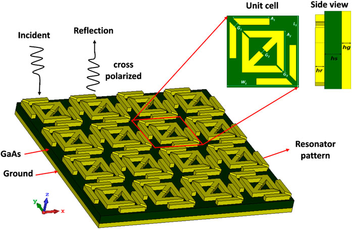
FIGURE 1. Schematic prototype of the proposed metasurface polarization converter with the front and side views of the unit cell in the inset figure. The dark green and yellow parts represent GaAs and Al, respectively.
The optimized dimensions were A1 = 61.05 µm, A2 = 68.45 µm, G1 = 7.85 µm, G2 = 7.15 µm, G3 = 2.2 µm, Ws = 120 μm, and Ls = 120 μm; the thickness of GaAs was 20 µm (hs), while the thickness of the metallic resonator was 11 µm (hr, hg).
Theoretical Analysis and Simulation Methodology
Interference theory [42] clarifies the co-polarized and cross-polarized reflectance coefficients. Interference theory can be applied when there is an interface between the metallic resonators and the dielectric substrate medium. The theory for the proposed metasurface polarization converter is depicted in Figure 2A. When a y-polarized wave is an incident on interface layer 1, then the polarized wave is transmitted to medium 2 from medium 1. However, some portion of the wave is reflected in medium 1. Since interface layer 1 is the interconnection of the metallic resonator and dielectric medium, it functions as a polarization converter. Thus, the transmitted and reflected waves will yield two components, y to y and y to x components denoting y-polarized and x-polarized waves, respectively. As the second interface layer 2 is grounded, it also serves as an interface layer of the metallic resonator and dielectric medium. Thus, when the transmitted wave is incident, some components will be reflected in the same medium 2 with negative unity, i.e.,
and the reflectance co-efficient for y to x is
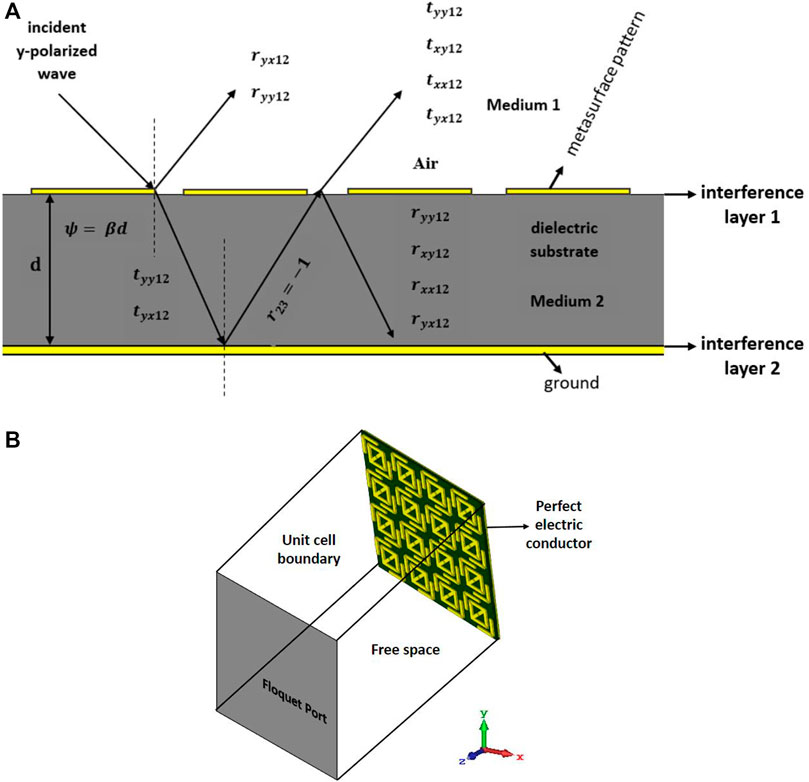
FIGURE 2. (A) Reflectance and transmission of waves based on interference theoretical model and (B) schematic description of simulation.
Similarly, the same occurs when an x-polarized wave incident on interface layer 1. For the x-polarized wave, the reflectance coefficient for x to x is
and the reflectance co-efficient for x to y is
Equations (1)–(4) were simplified for the clarification of the model where higher-order multiple reflected components are neglected [43, 44]. The terms
To control the polarization state of the electromagnetic waves through the metasurface, it is necessary to accurately simulate the metasurface structure. In this regard, the finite integration technique (FIT)-based CST microwave electromagnetic simulator (CST Studio Suite 2019) was used for the design, numerical calculations, and characteristic analysis. During the simulation, the proposed metasurface was placed in the x- and y-direction, where the unit cell boundary conditions were imposed so that infinite unit cells were assumed to make the simulation more accurate. The positive z-direction was set as an open space boundary condition with the applied floquet port, while for the negative z-axis, the perfect electric conductor boundary was used to ensure the occurrences of reflectance only. The boundary condition of the proposed metasurface is depicted in Figure 2B. The numerical simulation was performed between 250 and 850 µm wavelength. Adaptive tetrahedral mesh refinement was also applied to get the results more accurately. Moreover, transverse electric (TE) and transverse magnetic (TM) waves have been utilized for the y-polarized and x-polarized wave simulation, respectively.
Results and Discussion
Based on the extant literature, in a common phenomenon, the intensity of the co-polarized reflectance coefficient should be lower than −3 dB (i.e., Rxx < −3 dB and Ryy < −3 dB) and the cross-polarized reflectance coefficient should be opposite of that of the co-polarized reflectance coefficient (i.e., Ryx ≥ -3 dB and Rxy ≥ -3 dB), resulting in a cross-polarization conversion performance of 70%. However, if the intensity of co-polarized reflective coefficient falls below -10 dB (i.e., Rxx < −10 dB and Ryy < −10 dB) or the cross-polarized reflectance is higher than -2 dB (i.e., Ryx ≥ −2 dB and Rxy ≥ −2 dB), the cross polarizer is deemed to be highly efficient. In this situation, the cross-polarization performance reaches 90% and more [45]. The metasurface achieved dual bandwidth operation because of the multi-resonance characteristics. Multiple resonances were recorded at 286.7 µm (1.046 THz), 298.25 µm (1.0055 THz), 586.1 µm (0.5115 THz), and 689.55 µm (0.4554 THz). In this study, the developed metasurface performed as a polarization plane converter at an efficiency rate of 90%. The co-polarized and cross-polarized reflectance coefficients for both the x-polarized and y-polarized waves are presented in Figures 3A,B, respectively.
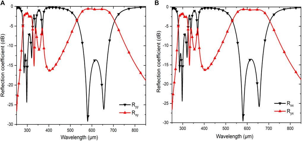
FIGURE 3. Simulated co- and cross-polarized reflectance coefficients for (A) y-polarized and (B) x-polarized waves.
Based on Figure 3, the co-polarized reflectance coefficients for both the x-polarized and y-polarized waves remained almost the same, i.e., less than −10 dB, whereas the cross-polarized reflectance coefficients for both the x-polarized and y-polarized waves were above −2 dB. Thus, the cross-polarization conversion was achieved from 282.9 to 302.3 µm (0.987–1.062 THz) and 558.78 to 676.7 µm (0.442–0.537 THz), signifying the conversions of the x-polarized wave into the y-polarized wave, and the y-polarized wave into the x-polarized wave, respectively. The cross-polarization efficiency was measured using PCR. The PCR for both the y-polarized and x-polarized waves was calculated as follows:
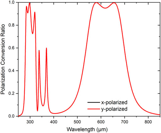
The magnitudes of PCR for the x- and y-polarized waves were plotted versus frequency spectrum as illustrated in Figure 4. The developed metasurface yielded above 90% polarization conversion efficiency from 282.9 to 302.3 µm and 558.78 to 676.7 µm. This result indicated that the developed metasurface could be used as an efficient polarization converter at a far-infrared range (0.3–1.2 THz).
To describe the multi resonance behavior of the metasurface for further clarification, the electric field distribution and surface current circulation for both the y- and x-polarized waves were assessed (Figure 5). At a higher frequency [i.e., 1.0055 THz (298.25 µm)], the electric charge is concentrated inside the splits of the array resonators. However, at the moderate resonance frequency [0.5115 THz (586.1 µm)], the charge concentration was more spread and concentrated at the corners of the resonators. As the frequency reduced, the electric charge concentration was spread to the corners and gaps [0.4554 THz (689.55 µm)]. However, some portions of resonators were weak in electric charge concentration, indicating decoupling characteristics at those regions. On the other hand, the black circle marks (O) represent the strong electric field, which leads to excellent electromagnetic coupling that defeats the decoupling portions to perform better. The electric charge concentration of the surface current distribution also justified the electric surface current distribution of the metasurface at different frequencies.
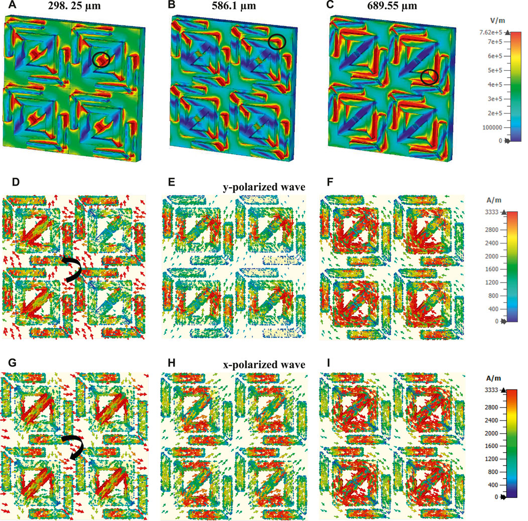
FIGURE 5. (A–C) Electric field distributions and surface current circulations for (D–F) y-polarized wave and (G–I) x-polarized wave at 298.25, 586.1, and 689.55 µm, respectively.
To realize the physical phenomena of the polarization conversion, the surface current distributions for the periodic resonator layer at the resonance frequencies were presented in Figure 5. Figures 5D–F and Figures 5G–I present the instantaneously induced current distributions at resonance frequencies of 298.25 µm (1.0055 THz), 586.1 µm (0.5115 THz), and 689.55 µm (0.4554 THz) for both the y- and x-polarized waves, respectively. As depicted in Figure 5D, when the y-polarized wave propagated through the metasurface structure, where an anti-clockwise current circulation occurred as indicated by the black sign at a resonance frequency of 298.25 µm. The current circulation can also be termed as anti-parallel current circulation. The anti-parallel current circulation could lead to magnetic dipole moments. The y-components of the induced magnetic field, which were also parallel to the incident electric field, led to the cross-coupling formation between the electric field and magnetic field. Subsequently, cross-polarization conversion from the y- to x-polarized state occurred. This cross-coupling effect was also produced for the resonance frequencies at 586.1 and 689.55 µm, as depicted in Figures 5E,F, because the y-polarized wave propagated and cross-polarization conversion occurred from the y- to x-polarized state [46]. When the x-polarized wave propagated through the metasurface, the current flowed in a clockwise direction (Figure 5G). The x-components of the induced magnetic field, which were perpendicular with the incident electric field, could not initiate cross-polarization conversion because the incident magnetic field was also in the same direction. However, the y-components of the induced magnetic field remained parallel with the incident electric field. Hence, it can induce the x-components perpendicular to the y-components of the electric field. Consequently, the induced x-components of the electric field led to polarization conversion. These phenomena occurred at 586.1 and 689.55 µm resonance frequencies, as depicted in Figures 5H,I, as the x-polarized wave was propagating.
The PCR performance of the metasurface was also examined under an increasingly oblique angle from 0 to 45° for the x- and y-polarized waves, as represented in Figures 6A,B, respectively. Based on the figures, the performance of the metasurface remained stable for bandwidths 556–679.9 µm (0.441 THz to 0.539 THz), despite the negligible changes. However, higher bandwidth affected the oblique incidence of the wave. The increase in the oblique incident angle (θ) also changed the magnitudes of the PCR due to the increase in the incident angle that greatly affected the reflected wave. The decrease in the cross-polarization component caused this reaction, whereby the bandwidth becomes narrower. However, in this study, angle stability was examined up to 45°, where 90% polarization efficiency was still achievable up to 30°, while the polarization efficiency dropped to 80% up to 45°.
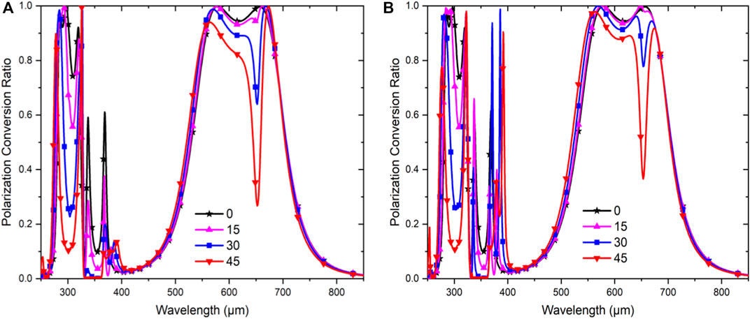
FIGURE 6. Computed PCR from 0 to 45-degree oblique incidence for (A) y-polarized wave and (B) x-polarized wave.
For the proper justification of the metasurface structure, the characteristics of the co-polarized and cross-polarized reflectance coefficients were analyzed against three critical parameters of the metasurface, namely, substrate thickness, split length (spotted at the middle of the two orthogonal arrows joining), and splits of the arrow shape of the square-shaped resonator (Figures 7A–F). To achieve the best characteristics of the co- and cross-polarized reflectance coefficients of the metasurface, the dielectric substrate thickness is considered an important parameter. Figures 7A,B displayed the co- and cross-polarized reflectance coefficients using the dielectric substrate at different thicknesses. According to the scale invariance of Maxwell, the substrate thickness and resonant frequency are inversely related. At higher frequencies, the substrate must have a minimum thickness for the unit cell to resonate. To achieve cross-polarization conversion over 90%, after a series of optimization processes, the thickness of the substrate was set at 20 µm. Increasing the thickness of the substrate, decrease the dB values of the co-polarized reflectance as well as the cross-polarized reflectance also tend to decrease higher than −2 dB. In those cases, the cross-polarization conversion could not be achieved, which is our main goal. On the other hand, the co-polarized reflectance coefficient lost its resonance at a higher frequency when the thickness of the substrate was reduced.
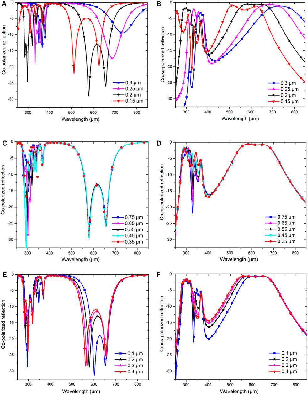
FIGURE 7. Co- and cross-polarized reflectance responses based on varying (A,B) substrate thickness, (C,D) split length, and (E,F) split gap at the corner of the square-shaped resonator.
The split at the middle of the two orthogonal arrows joining is responsible for the metasurface response at higher frequency (i.e., the resonance at 286.7 and 298.25 µm occurred due to the split creation). The split also leads to an increased capacitance of the inside resonator and yields higher frequency resonances. After a series of optimization processes, the split width in this study was set at 55 µm. Moreover, there is an inverse relationship between capacitance and resonant frequency. As depicted in Figures 7C,D, we discovered better co-polarized reflectance characteristics with resonance dip at higher frequencies that were valuable in medical imaging applications. The splits at the corner of the square-shaped resonator were also an important factor in creating an arrow-shaped structure. Figures 7E,F display the co- and cross-polarized reflectance coefficients for varying gaps of splits. Following numerous analyses, the optimum value for the splits of the corner was set as 0.2 µm. Increasing the gap deteriorates the resonance frequencies due to the decrease in capacitance and gap that reduces the bandwidth.
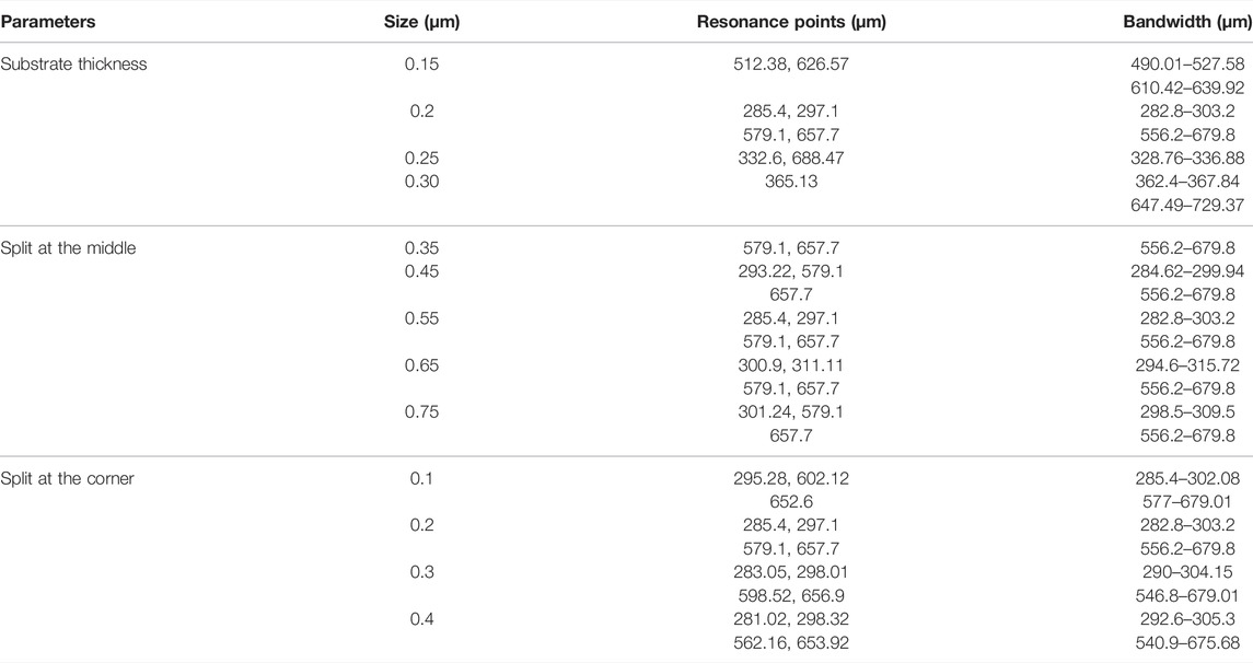
Table 1 summarizes the analytical results of the crucial parameters of the designed structure. When the substrate thickness changes, the resonance frequencies and bandwidth also changed. The split in the middle, which is responsible for the first two low resonance frequencies, changed with different split lengths, except for two other resonance peaks that were almost stable regardless of the changes. Then, the splits in the two corners, which are responsible for the two upper resonance frequencies, are changing with changes of the split length, and for this case, the lower two frequencies saw minor shifting. Overall, the combination of 0.2 µm substrate thickness, 0.55 µm split at the middle, and 0.2 µm splits at two corners demonstrated that the proposed metasurface yielded the best results for polarization conversion.
Due to the inadequate facilities, the metasurface device could not be fabricated. However, the metasurface polarization converter can be fabricated using ultraviolet (UV) lithography and lift-off process [47, 48]. The steps are given below:
1) At first, a supporting substrate (Si or Ti) needs to fabricate by the e-beam evaporation process so that the whole structure of the metasurface can be fabricated onto it.
2) Second, the ground metallic layers, which was Al, can be evaporated evenly on the skin of the supporting substrate.
3) After that, with the technologies of spin-coating, the middle dielectric layer can be consistently coated over the surface of the Al layer.
4) At last, the top metallic array pattern (Al) can be fabricated by utilizing conventional lithography and lift-off processes of micro-fabrication.
By following these steps, the proposed metasurface device can be fabricated and experimentally measured utilizing the fiber-coupled THz time-domain spectrometer (THz-TDS) system.
Table 2 summarizes and compares the findings from the reported literature with the proposed design. Based on the results, every metasurface that was designed for polarization conversion either involved cross-polarization or linear to circular polarization conversion. Comparatively, previous studies which utilized double-layered or multi-layered designs were complicated to fabricate and were costly as they used materials such as graphene and gold. Thus, the need for a single layer, low-cost, and compact metasurface was still in demand. The proposed work is a suitable candidate for the metasurface resonator array pattern.
Conclusion
A proposed metasurface was numerically described for efficient polarization conversion in this study. The interference theory was used to discuss the model. Exhibiting the anisotropy of the metasurface structure, the metasurface yielded a 90% polarization converter from x- to y-polarization, and vice versa from 282.9 to 302.3 µm and 558.78 to 676.7 µm. The metasurface structure was also angle independent up to 30°. The metasurface was examined using different parameters to assess its potentiality as an efficient polarization converter. Finally, the compact size, angular stability performance, and numerous features make the proposed single-layered metasurface a potential candidate for advanced THz applications, including THz detectors, sensing, and many other THz-based devices.
Data Availability Statement
The original contributions presented in the study are included in the article/Supplementary Material, further inquiries can be directed to the corresponding author.
Author Contributions
Conceptualization—AT and MH; methodology—AT; software—AT; formal analysis—AT and MH; writing—AT and MH; writing—review and editing—MH, MF; supervision—MF; funding acquisition—MF. All authors have read and agreed to the published version of the manuscript.
Funding
This work was supported by the Research Universiti Grant, Universiti Kebangsaan Malaysia, Geran Universiti Penyelidikan (GUP), code: 2021-074.
Conflict of Interest
The authors declare that the research was conducted in the absence of any commercial or financial relationships that could be construed as a potential conflict of interest.
Publisher’s Note
All claims expressed in this article are solely those of the authors and do not necessarily represent those of their affiliated organizations, or those of the publisher, the editors and the reviewers. Any product that may be evaluated in this article, or claim that may be made by its manufacturer, is not guaranteed or endorsed by the publisher.
References
1. Holloway CL, Dienstfrey A, Kuester EF, O’Hara JF, Azad AK, Taylor AJ. A Discussion on the Interpretation and Characterization of Metafilms/metasurfaces: The Two-Dimensional Equivalent of Metamaterials. Metamaterials (2009) 3:100–12. doi:10.1016/j.metmat.2009.08.001
2. Cheng Y, Fan J, Luo H, Chen F. Dual-band and High-Efficiency Circular Polarization Convertor Based on Anisotropic Metamaterial. IEEE Access (2020) 8:7615–21. doi:10.1109/ACCESS.2019.2962299
3. Wang B-X, He Y, Lou P, Zhu H. Multi-band Terahertz Superabsorbers Based on Perforated Square-Patch Metamaterials. Nanoscale Adv (2021) 3(2):455–62. doi:10.1039/D0NA00903B
4. Ahamed E, Faruque MRI, Alam MJ, Mansor MFB, Islam MT. Digital Metamaterial Filter for Encoding Information. Sci Rep (2020) 10(1):1–9. doi:10.1038/s41598-020-60170-8
5. Wang B-X, Wu Y, Xu W, Yang Z, Lu L, Pi F. Quad-band Terahertz Metamaterial Absorber Enabled by an Asymmetric I-type Resonator Formed from Three Metallic Strips for Sensing Application. Sens Diagn (2022) 1:169–76. doi:10.1039/D1SD00005E
6. Alam MJ, Ahamed E, Faruque MRI, Islam MT, Tamim AM. Left-handed Metamaterial Bandpass Filter for GPS, Earth Exploration-Satellite and WiMAX Frequency Sensing Applications. PloS one (2019) 14(11):e0224478. doi:10.1371/journal.pone.0224478
7. Tamim AM, Hasan MM, Faruque MRI, Islam MT, Nebhen J. Polarization-independent Symmetrical Digital Metasurface Absorber. Results Phys (2021) 24:103985. doi:10.1016/j.rinp.2021.103985
8. Chen H-T, Taylor AJ, Yu N. A Review of Metasurfaces: Physics and Applications. Rep Prog Phys (2016) 79(7):076401. doi:10.1088/0034-4885/79/7/076401
10. Zhao Y, Alù A. Manipulating Light Polarization With Ultrathin Plasmonic Metasurfaces. Phys Rev B (2011) 84(20):205428. doi:10.1103/PhysRevB.84.205428
11. Khan MI, Tahir FA. A Compact Half and Quarter-Wave Plate Based on Bi-layer Anisotropic Metasurface. J Phys D: Appl Phys (2017) 50:43LT04. doi:10.1088/1361-6463/aa86d6
12. Chang C-C, Headland D, Abbott D, Withayachumnankul W, Chen H-T. Demonstration of a Highly Efficient Terahertz Flat Lens Employing Tri-layer Metasurfaces. Opt Lett (2017) 42:1867. doi:10.1364/ol.42.001867
13. Akram MR, Mehmood MQ, Tauqeer T, Rana AS, Rukhlenko ID, Zhu W. Highly Efficient Generation of Bessel Beams with Polarization Insensitive Metasurfaces. Opt Express (2019) 27:9467. doi:10.1364/oe.27.009467
14. Yoon G, Lee D, Nam KT, Rho J. Geometric Metasurface Enabling Polarization Independent Beam Splitting. Sci Rep (2018) 8(1):1–8. doi:10.1038/s41598-018-27876-2
15. Su P, Zhao Y, Jia S, Shi W, Wang H. An Ultra-Wideband and Polarization-Independent Metasurface for RCS Reduction. Sci Rep (2016) 6(1):1–8. doi:10.1038/srep20387
16. Azad AK, Efimov AV, Ghosh S, Singleton J, Taylor AJ, Chen H-T. Ultra-thin Metasurface Microwave Flat Lens for Broadband Applications. Appl Phys Lett (2017) 110:224101. doi:10.1063/1.4984219
17. Huang L, Zhang S, Zentgraf T. Metasurface Holography: From Fundamentals to Applications. Nanophotonics (2018) 7(6):1169–1190. doi:10.1515/nanoph-2017-0118
18. Faruque MRI, Hasan MM, Islam MT. Tree-shaped Fractal Meta-Surface with Left-Handed Characteristics for Absorption Application. Appl Phys A (2018) 124:1–8. doi:10.1007/s00339-017-1498-9
19. Cheng Y, Zhu X, Li J, Chen F, Luo H, Wu L. Terahertz Broadband Tunable Reflective Cross-Polarization Convertor Based on Complementary Cross-Shaped Graphene Metasurface. Physica E: Low-dimensional Syst Nanostructures (2021) 134:114893. doi:10.1016/j.physe.2021.114893
20. Cheng Y, Wang J. Tunable Terahertz Circular Polarization Convertor Based on Graphene Metamaterial. Diamond Relat Mater (2021) 119:108559. doi:10.1016/j.diamond.2021.108559
21. Feng M, Wang J, Ma H, Mo W, Ye H, Qu S. Broadband Polarization Rotator Based on Multi-Order Plasmon Resonances and High Impedance Surfaces. J Appl Phys (2013) 114:074508. doi:10.1063/1.4819017
22. Zhang L, Zhou P, Lu H, Chen H, Xie J, Deng L. Ultra-thin Reflective Metamaterial Polarization Rotator Based on Multiple Plasmon Resonances. Antennas Wirel Propag Lett (2015) 14:1157–60. doi:10.1109/LAWP.2015.2393376
23. Chen H, Wang J, Ma H, Qu S, Xu Z, Zhang A, et al. Ultra-wideband Polarization Conversion Metasurfaces Based on Multiple Plasmon Resonances. J Appl Phys (2014) 115:154504. doi:10.1063/1.4869917
24. Cheng Y, Fan J, Luo H, Chen F, Feng N, Mao X, et al. Dual-band and High-Efficiency Circular Polarization Conversion via Asymmetric Transmission with Anisotropic Metamaterial in the Terahertz Region. Opt Mater Express (2019) 9:1365. doi:10.1364/ome.9.001365
25. Jiang Y, Zhao H, Wang L, Wang J, Cao W, Wang Y. Broadband Linear-To-Circular Polarization Converter Based on Phosphorene Metamaterial. Opt Mater Express (2019) 9:2088. doi:10.1364/ome.9.002088
26. Zhu J, Li S, Deng L, Zhang C, Yang Y, Zhu H. Broadband Tunable Terahertz Polarization Converter Based on a Sinusoidally-Slotted Graphene Metamaterial. Opt Mater Express (2018) 8:1164. doi:10.1364/ome.8.001164
27. Wen X, Zheng J. Broadband THz Reflective Polarization Rotator by Multiple Plasmon Resonances. Opt Express (2014) 22:28292. doi:10.1364/oe.22.028292
28. Cheng Z, Cheng Y. A Multi-Functional Polarization Convertor Based on Chiral Metamaterial for Terahertz Waves. Opt Commun (2019) 435:178–82. doi:10.1016/j.optcom.2018.11.038
29. Ako RT, Lee WSL, Atakaramians S, Bhaskaran M, Sriram S, Withayachumnankul W. Ultra-wideband Tri-layer Transmissive Linear Polarization Converter for Terahertz Waves. APL Photon (2020) 5:046101. doi:10.1063/1.5144115
30. Borgese M, Costa F, Genovesi S, Monorchio A, Manara G. Optimal Design of Miniaturized Reflecting Metasurfaces for Ultra-Wideband and Angularly Stable Polarization Conversion. Sci Rep (2018) 8(1):1–11. doi:10.1038/s41598-018-25934-3
31. Fan J, Cheng Y. Broadband High-Efficiency Cross-Polarization Conversion and Multi-Functional Wavefront Manipulation Based on Chiral Structure Metasurface for Terahertz Wave. J Phys D: Appl Phys (2020) 53:025109. doi:10.1088/1361-6463/ab4d76
32. Zhang J, Zhang K, Cao A, Liu Y, Kong W. Bi-functional Switchable Broadband Terahertz Polarization Converter Based on a Hybrid Graphene-Metal Metasurface. Opt Express (2020) 28:26102. doi:10.1364/oe.397338
33. Li J, Li J, Yang Y, Li J, Zhang Y, Wu L, et al. Metal-graphene Hybrid Active Chiral Metasurfaces for Dynamic Terahertz Wavefront Modulation and Near Field Imaging. Carbon (2020) 163:34–42. doi:10.1016/j.carbon.2020.03.019
34. Li J, Zheng C, Li J, Wang G, Liu J, Yue Z, et al. Terahertz Wavefront Shaping with Multi-Channel Polarization Conversion Based on All-Dielectric Metasurface. Photon Res (2021) 9(10):1939–47. doi:10.1364/PRJ.431019
35. Serita K, Matsuda E, Okada K, Murakami H, Kawayama I, Tonouchi M. Invited Article: Terahertz Microfluidic Chips Sensitivity-Enhanced with a Few Arrays of Meta-Atoms. APL Photon (2018) 3:051603. doi:10.1063/1.5007681
36. Tang M, Zhang M, Yan S, Xia L, Yang Z, Du C, et al. Detection of DNA Oligonucleotides With Base Mutations by Terahertz Spectroscopy and Microstructures. PLoS One (2018) 13(1):e0191515. doi:10.1371/journal.pone.0191515
37. Han X, Yan S, Zang Z, Wei D, Cui H-L, Du C. Label-free Protein Detection Using Terahertz Time-Domain Spectroscopy. Biomed Opt Express (2018) 9:994. doi:10.1364/boe.9.000994
38. Rahman A, Rahman AK, Rao B. Early Detection of Skin Cancer via Terahertz Spectral Profiling and 3D Imaging. Biosens Bioelectron (2016) 82:64–70. doi:10.1016/j.bios.2016.03.051
39. Lee K, Jeoung K, Kim SH, Ji Y-b., Son H, Choi Y, et al. Measuring Water Contents in Animal Organ Tissues Using Terahertz Spectroscopic Imaging. Biomed Opt Express (2018) 9:1582. doi:10.1364/boe.9.001582
40. Zhao H, Wang X, He J, Guo J, Ye J, Kan Q, et al. High-efficiency Terahertz Devices Based on Cross-Polarization Converter. Sci Rep (2017) 7(1):1–9. doi:10.1038/s41598-017-18013-6
41. Ahamed E, Faruque MRI, Mansor MFB, Islam MT. Polarization-dependent Tunneled Metamaterial Structure with Enhanced fields Properties for X-Band Application. Results Phys (2019) 15:102530. doi:10.1016/j.rinp.2019.102530
42. Chen H-T. Interference Theory of Metamaterial Perfect Absorbers. Opt Express (2012) 20:7165. doi:10.1364/oe.20.007165
43. Gao X, Han X, Cao W-P, Li HO, Ma HF, Cui TJ. Ultrawideband and High-Efficiency Linear Polarization Converter Based on Double V-Shaped Metasurface. IEEE Trans Antennas Propagat (2015) 63:3522–30. doi:10.1109/TAP.2015.2434392
44. Kundu D, Mohan A, Chakrabarty A. Reduction of Cross-Polarized Reflection to Enhance Dual-Band Absorption. J Appl Phys (2016) 120:205103. doi:10.1063/1.4968569
45. Salman MS, Khan MI, Tahir FA, Rmili H. Multifunctional Single Layer Metasurface Based on Hexagonal Split Ring Resonator. IEEE Access (2020) 8:28054–63. doi:10.1109/ACCESS.2020.2971557
46. Grady NK, Heyes JE, Chowdhury DR, Zeng Y, Reiten MT, Azad AK, et al. Terahertz Metamaterials for Linear Polarization Conversion and Anomalous Refraction. Science (2013) 340(6138):1304–7. doi:10.1126/science.1235399
47. Huang L, Chowdhury DR, Ramani S, Reiten MT, Luo S-N, Taylor AJ, et al. Experimental Demonstration of Terahertz Metamaterial Absorbers with a Broad and Flat High Absorption Band. Opt Lett (2012) 37(2):154–6. doi:10.1364/OL.37.000154
Keywords: metasurface, polarization conversion, terahertz, x-polarized, y-polarized
Citation: Tamim AM, Hasan MM and Faruque MRI (2022) Highly Efficient Metasurface Polarization Converter at Far-Infrared Range. Front. Phys. 10:890356. doi: 10.3389/fphy.2022.890356
Received: 05 March 2022; Accepted: 25 March 2022;
Published: 27 April 2022.
Edited by:
Kai-Da Xu, Xi’an Jiaotong University, ChinaReviewed by:
Jie Li, Tianjin University, ChinaBen-Xin Wang, Jiangnan University, China
Yongzhi Cheng, Wuhan University of Science and Technology, China
Xiang Wan, Southeast University, China
Copyright © 2022 Tamim, Hasan and Faruque. This is an open-access article distributed under the terms of the Creative Commons Attribution License (CC BY). The use, distribution or reproduction in other forums is permitted, provided the original author(s) and the copyright owner(s) are credited and that the original publication in this journal is cited, in accordance with accepted academic practice. No use, distribution or reproduction is permitted which does not comply with these terms.
*Correspondence: Mohammad Rashed Iqbal Faruque, cmFzaGVkQHVrbS5lZHUubXk=
 Ahmed Mahfuz Tamim
 Md Mehedi Hasan
 Mohammad Rashed Iqbal Faruque