 Oliver Brüning
 Andrei Seryi
 Silvia Verdú-Andrés
- 1European Organization for Nuclear Research, Geneva, Switzerland
- 2Thomas Jefferson National Accelerator Facility, Newport News, VA, United States
- 3Brookhaven National Laboratory, Upton, NY, United States
Electron-hadron colliders are the ultimate tool for high-precision quantum chromodynamics studies and provide the ultimate microscope for probing the internal structure of hadrons. The electron is an ideal probe of the proton structure because it provides the unmatched precision of the electromagnetic interaction, as the virtual photon or vector bosons probe the proton structure in a clean environment, the kinematics of which is uniquely determined by the electron beam and the scattered lepton, or the hadronic final state accounting appropriately for radiation. The Hadron Electron Ring Accelerator HERA (DESY, Hamburg, Germany) was the only electron-hadron collider ever operated (1991–2007) and advanced the knowledge of quantum chromodynamics and the proton structure, with implications for the physics studied in RHIC (BNL, Upton, NY) and the LHC (CERN, Geneva, Switzerland). Recent technological advances in the field of particle accelerators pave the way to realize next-generation electron-hadron colliders that deliver higher luminosity and enable collisions in a much broader range of energies and beam types than HERA. Electron-hadron colliders combine challenges from both electron and hadron machines besides facing their own distinct challenges derived from their intrinsic asymmetry. This review paper will discuss the major features and milestones of HERA and will examine the electron-hadron collider designs of the Electron-Ion Collider (EIC) currently under construction at BNL, the CERN’s Large Hadron electron Collider (LHeC), at an advanced stage of design and awaiting approval, and the Future Circular lepton-hadron Collider (FCC-eh).
1 Introduction
The internal structure of the proton has been a fundamental research topic since the discovery of the proton by Rutherford. First measurements of the proton structure were performed in the 1950s at the Stanford Linear Accelerator (SLAC), yielding a resolution of the proton structure at near femtometer scales and identifying a finite proton radius [1]. Subsequent measurements at SLAC in the 1960s, Fermi National Accelerator Laboratory (FNAL) in the 1970s and the European Organization for Nuclear Research (CERN) in the 1980s improved the resolution of the proton structure by more than two orders of magnitude, revealing the quark structure of the proton and the quark-gluon dynamics inside the proton. The Hadron Electron Ring Accelerator (HERA) at the Deutsches Elektronen-Synchrotron (DESY) laboratory was the first dedicated high center-of-mass energy electron-proton collider and pushed the proton structure resolution down to the attometer scale. The measured proton structure functions from HERA were, in turn, a vital ingredient for the precision measurements at the CERN’s Large Hadron Collider (LHC) that led to the discovery of the Higgs particle in 2012 [2, 3]. Additional insight into the proton structure has been attained at the Relativistic Heavy Ion Collider (RHIC) at Brookhaven National Laboratory (BNL), where high-energy collisions between polarized proton beams enable the study of the contribution of quarks and gluons to the proton spin [4]. Pushing the energy frontier in future hadron collider facilities beyond the TeV scale requires knowledge of the proton structure function at even smaller scales. The Large Hadron Electron Collider (LHeC) and the Future Circular Collider (FCC) could cater to this task. Furthermore, with luminosities above 1034 cm−2 s−1 at hand, the LHeC could also be a Higgs factory and enable new searches for physics beyond the Standard Model [5]. The HERA collider did not provide polarized proton beams and did not explore the regime of electron-ion collisions. The Electron-Ion Collider (EIC) under construction at BNL will address these aspects in the coming decades and explore QCD aspects not studied by HERA [6, 7], focusing on the central goal of modern nuclear physics – to understand the structure of the proton and neutron directly from the dynamics of their quarks and gluons governed by the theory of their interaction (quantum chromodynamics), and how nuclear interactions between protons and neutrons emerge from these dynamics.
HERA featured asymmetric collisions between beams of different species and energies (most commonly protons at 920 GeV and electrons or positrons at 27 GeV). The operational experience of HERA showed the general feasibility of such an asymmetric collision scheme in circular collider/storage ring configurations and confirmed the necessity – similarly observed by the Super Proton–Antiproton Synchrotron (Sp
The EIC will use the RHIC accelerator complex. In operation since 2000, RHIC is the first heavy-ion collider and also the world’s only spin-polarized proton collider. A versatile machine, it provides collisions between beams with a wide range of particle species (p ↑, Au, U, …) and energies (3.85–100 GeV/u for Au and up to 255 GeV for protons). Transverse and longitudinal stochastic cooling based on microwave technology helps to counteract intra-beam scattering (IBS) of high-energy, bunched ion beams for prolonged luminosity lifetime [16]. The luminosity of low-energy ion collisions is also enhanced thanks to a hadron cooling system that uses RF accelerated electron bunches [17]. Two full Siberian snakes (spin rotators) in each ring enable high luminosity collisions of polarized proton beams at 255 GeV, with a polarization up to 55% averaged over a full store and over the two beams [18]. The EIC will combine the experience from HERA to deliver polarized electron beams with the experience from RHIC to be the first machine that provides the collision of polarized electrons with polarized protons, and at a later stage, polarized 2H and 3He.
The LHeC and FCC-eh collider designs build on the experience of the HERA collider and the recent developments for Energy Recovery Linear accelerators (ERL). The ERL design allows a modular collider design that can be applied to the LHC, the High Energy LHC (HE-LHC) and the FCC hadron storage rings while minimizing the energy requirements for the operation of the collider and providing the maximum performance reach for peak luminosity, promising values in excess of 1034 cm−2s−1. Both LHeC and FCC-eh implementations are conceived for concurrent operation in parallel to the main program of the hadron colliders and an ensuing dedicated exploitation phase once the main hadron beam physics program has been completed. This paper focuses on the designs of EIC, LHeC and FCC-eh. This is not an exclusive list. Alternatives at a conceptual design stage like the plasma-based particle colliders are looked at in the context of the European Particle Physics Strategy Update (EPPSU) and the associate lab directors group [19], as well as in the ongoing Snowmass 2021 community process [20].
2 Design Options
An electron-hadron collider has essentially two basic design options: 1) a ring-ring based collider design where both the electron and the hadron beams circulate in opposite directions in storage rings that intersect with each other at one or more locations to enable collisions between the two beams, or 2) a linac-ring based collider design where the hadron beam circulates in a storage ring and collides at one location with electrons from a linear accelerator.
A ring-ring based design is the most efficient collider design as it allows both beams to collide with each other repeatedly. However, its performance is eventually limited by the power loss due to synchrotron radiation of the electron beam, the emittance of the electron beam that is defined by the synchrotron radiation damping and tune shifts caused by the beam-beam interactions at the interaction point. For the LHeC goals, these effects essentially limit the peak performance reach of the collider to luminosities around 1033 cm−2 s−1 [21].
Accelerating the electrons through a linear accelerator minimizes the synchrotron radiation losses, but exposes the electron beam only once to a collision with the hadron beam, thus eliminating the beam-beam tune shift limitation, and allows a better match of the electron beam size to that of the hadron beam as the electron beam emittance is entirely determined by the source. However, a linac-ring design concept allows only one collision of the electron beam with the hadron beam before the electron beams are discarded. The performance reach of this design concept is therefore directly linked to the maximum affordable electron beam power. Again, practical limitations imply for the LHeC concept luminosities around 1033 cm−2 s−1.
The use of ERLs provides a very appealing alternative design variation of the linac-ring concept. An ERL-based collider design allows, at least in principle, the recuperation of the electron beam power after the collisions with the hadron beam, and thus eliminates the electron beam power limit on the performance. Exposing the electron beam only once to a collision before deceleration and discarding the electron beams after the deceleration further eliminates the limitations of the beam-beam parameter and the electron beam emittances on the performance reach. Assuming an ERL layout with return arcs, where the beam passes through the same RF system during the acceleration and deceleration phases, the total synchrotron radiation power loss is only marginally smaller in an ERL-based design when compared to a ring-ring design of comparable size and bending radius (ca. 70% [21]). However, the elimination of the electron power limit and the beam-beam tune shift limit opens the door to a much higher performance reach and, for the LHeC, opens the door to luminosities above 1034 cm−2 s−1. This boost in the performance reach comes at the price of relying on a new accelerator concept (ERL) and its challenging operation mode. Any design of a future electron-hadron collider needs therefore to find a good compromise between performance limitations with well-established accelerator concepts and pushing the performance with the help of R&D accelerator concepts.
The above described methodology was fully employed in the development of the United States.based EIC project. While the earlier concepts of the EIC included considerations of a linac-ring concept, where the electron beam was provided by an ERL based on high number of recirculations through a linac and a special Fixed-Field Alternating gradient (FFA) circular beam transport, a comprehensive review [22] found that the “unproven or demanding technical components” of the linac-ring EIC concept with FFAs and large number of recirculations “present both technical and cost risks and will require substantial R&D to be proven reliable and cost effective”. Consequently, the more established ring-ring concept was adopted for the United States EIC, which is now an approved project, proceeding to technical design and soon expected to start construction.
3 Common Challenges and Enabling Technologies
The concept of ERLs was already proposed in the 1960s [23]. A key technological ingredient for the ERL concept is the realization of RF systems with a sufficiently high Q0 that allow an efficient storage of the electromagnetic fields between deceleration and acceleration cycles. This only became feasible with recent advancements in superconducting RF (SRF) technology that allow accelerating gradients of the order of 20 MV/m with Q0 > 1010 [24–26]. The higher the Q0 and the lower the losses through Higher Order Modes (HOMs), the more efficient the ERL. Ultimately one substitutes the beam power limitations of a conventional linac with the limitations of the cryogenic system for the ERL that is required for cooling the heat dissipation from the operating mode and HOMs. A second design goal, in addition to the highest possible Q0, is therefore the development of high-temperature SRF systems that allow a more efficient cooling [e.g., operation at 4 K] and lower cryogenic loads of the SRF system [27, 28]. SRF developments are therefore a critical enabling technology for the ERL-based collider concepts.
A second required enabling technology for ERL-based colliders and cooling systems of future electron-hadron colliders is the development of high average current, high brightness, low emittance electron (and positron) sources with long cathode lifetimes. Record high brightness, high average current non-polarized electron sources use DC guns [29]. Most recently an SRF gun, continuous-wave (CW) operated and equipped with an alkali CsK2Sb photocathode, provided high-charge electron beams with small transverse emittance and remarkably long lifetimes of up to a month in stable, continued operation [30, 31]. The availability of efficient spin-polarized electron sources is, on the other hand, relevant for electron-hadron colliders like the EIC. GaAs photocathodes are the preferred choice for spin-polarized electron sources [32]. Strained superlattice GaAs cathodes routinely achieve spin polarization above 80% and, in the last years, the use of Distributed Bragg Reflectors (DBR) has boosted their quantum efficiency to a few percentage points [33]. In general, polarized electron sources feature lifetimes of a few days, modest when compared to the non-polarized electron sources.
The introduction of a crossing angle to reduce long-range beam-beam interactions can have a severe impact on the instantaneous luminosity due to the partial geometric overlap of the colliding bunches and the coupling of synchrotron and betatron oscillations [34]. To circumvent this issue, HERA implemented a head-on collision scheme at the expense of adopting a large bunch spacing. The KEK-B electron-positron collider at the High Energy Accelerator Research Organization (KEK) opted instead for a large crossing angle of 22 mrad and demonstrated in the 2000s the full recovery of head-on collisions between electron and positron bunches with crab cavities [35]. Simulations had shown that crab crossing would not only increase luminosity by enabling a full geometric overlap of the colliding bunches but also by its effect on the associated beam-beam tune shift [36]. The High Luminosity LHC (HL-LHC) will be the first collider to use crab cavities for the recovery of head-on collisions between proton bunches [37]. Crabbing of proton bunches was recently demonstrated in the CERN’s Super Proton Synchrotron (SPS) [38].
Crab cavities are transversely deflecting RF cavities that provide a transverse kick of the same magnitude but opposite sign to the head and tail of the bunch [39]. Long hadron bunches favor the use of low frequency cavities to avoid a non-linear crabbing kick [40] that may introduce higher-order synchrobetatron oscillations [41]. Located in the interaction region where typically space constraints are tight, crab cavities are required to be compact and feature a large aperture. High luminosity colliders rely on a high bunch rate that motivates CW operation. Low frequency, large aperture, and CW operation requirements drive the choice of SRF technology for most crab cavities (with the exception of the linear collider CLIC). Compact crab cavity designs have been developed for the HL-LHC crabbing system and the EIC [42–47]. The impedance of the EIC crabbing systems can introduce dangerous transverse instabilities, so a high-gain feedback will reduce the impedance of the crab cavities, to be complemented with a transverse damping system during injection and ramping [48]. The high sensitivity of the hadron beam to RF noise in the crab cavities, in the order of that found for HL-LHC, will also require the implementation of an RF noise feedback [49] as also planned for HL-LHC.
Both HERA and EIC have substantially asymmetric beam energies. To guarantee synchronicity between the colliding beams for a broad range of hadron beam energies outside of the ultra-relativistic regime, at certain energies the EIC hadron beam circulates with a significant radial offset (tens of mm) with respect to the nominal beam pipe size (69 mm diameter) that consequently increases the impedance. In HERA, the minimum energy of the colliding protons (300 GeV) was defined by the maximum orbit change that could be implemented. The different rigidity of the beams also becomes important in the detector solenoid. An uncompensated solenoidal field may compromise the high luminosity as it can introduce closed orbit distortions, transverse beam focusing, transverse coupling, couple longitudinal and transverse planes of crabbed bunches, and impact the polarization of the beams [50, 51]. While the detector solenoid field was uncompensated in HERA, several compensation techniques are planned for the EIC [52, 53].
The typically dense and complex interaction regions of any collider also encounter challenges from the strong synchrotron radiation emitted by leptons and high-energy protons as a result of their passage through separation and focusing magnets. Synchrotron radiation can cause severe heating of equipment and be a direct and indirect source of detector background through backscattered photons and products of the interaction between the beam and photodesorbed molecules. HERA-II had synchrotron radiation absorbers far away from the detector and the low beta quadrupoles to reduce the detector background from backscattered photons [54, 55]. The IR vacuum chambers of the EIC, LHeC and FCC-eh are also a focus of attention [56].
4 EIC
The EIC is a United States DOE project with critical decision 1 (CD-1) approval. The EIC is designed to collide 5–18 GeV polarized electron beams with 41–275 GeV polarized proton beams, polarized light ions with energies up to 166 GeV/u as is the case of 3He, and unpolarized heavy ion beams up to 110 GeV/u [57]. Although the EIC project scope only includes one interaction region, two colliding beam interaction regions and detectors are feasible. The EIC will be built upon the infrastructure of the RHIC complex. Several arcs of the two independent superconducting rings of RHIC will become the hadron storage ring of the EIC. The present injector chain of RHIC will be reused for the EIC. Two electron rings will be added to the tunnel to complete the EIC: a rapid-cycling synchrotron will accelerate the electron beams to storage energy before the beams are injected into the electron storage ring. Strong hadron cooling will be necessary to guarantee the delivery of an electron-proton peak luminosity of 1034 cm−2 s−1 at 105 GeV center-of-mass energy. Construction of the EIC is planned to start in 2024, with first operations beginning early in the next decade. Figure 1 shows the EIC layout with its main components [58, 59].
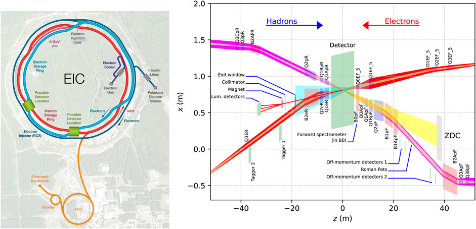
FIGURE 1. Artistic rendition of the EIC layout and its preliminary interaction region.
Like other high luminosity colliders, the EIC design must address challenges associated with high intensity beams and the attainment of small emittances at the interaction points. The maximum average current for the electron beam circulating in the EIC electron storage ring is limited to 2.5 A for the 5 and 10 GeV electron beams and 0.25 A for the 18 GeV electron beam in order to keep the synchrotron radiation power loss below 10 MW. This power will be restored by seventeen or eighteen 591 MHz single-cell SRF cavities, each equipped with a pair of MW-level CW power couplers [60]. In addition to the challenges derived from high power handling, the variety of beam energies and currents for EIC operation require that these couplers cover a broad range of power levels and couplings. The high luminosity scenario of the EIC will use a 1 A average current proton beam with 10 ns-spaced, 6.9 × 10¹⁰ ppb bunches. The EIC will be the electron-hadron collider with smallest bunch spacing. To impede the formation of electron clouds, the vacuum chamber of the EIC hadron storage ring – that of RHIC – will need surfaces with low secondary electron yield (SEY). Arc quadrupoles and sextupoles, which can behave as magnetic bottles for the electron cloud forming after the passage of off-centered beams, present particularly low SEY thresholds close to 1. Electron clouds were effectively suppressed by NEG coating the warm beamline sections of RHIC [61] and the vacuum chamber of the EIC hadron storage ring will as well use NEG coating in the warm beamline sections of the EIC hadron storage ring. The cold sections of RHIC currently have a stainless steel beam pipe, a material with large electric resistivity and high SEY. As part of the conversion of RHIC into the EIC hadron storage ring, the vacuum chamber of the reutilized cold beamline sections will be equipped with a beam screen featuring a copper layer for reduced resistive-wall power losses under a thin amorphous carbon layer for electron cloud suppression [62]. Amorphous carbon is an electron cloud mitigator with SEY close to unity developed over the last decade for use in several proton accelerators of the CERN complex [63].
Acceleration of the hadron beam is currently planned to use two 24.6 MHz quarter-wave resonator (QWR) cavities for capture and acceleration (currently operating at 28 MHz for RHIC, which features a different operation frequency and number of bunches), two 49.3 MHz QWR cavities and two 98.5 MHz QWR cavities for splitting and six existing 197 MHz re-entrant cavities for compression and store, all normal conducting, plus one 591 MHz 5-cell SRF cavity [64, 65]. The same 5-cell SRF cavity design is foreseen for acceleration in the RCS (three cavities) and the ERL (ten fundamental frequency cavities and three third harmonic cavities). The 10 MW power lost by the electron beam into synchrotron radiation will be restored by seventeen or eighteen 591 MHz single-cell SRF cavities, to be installed in about nine slots of 8 m length each. While the current design envisions one cavity per cryomodule, putting two cavities per cryomodule is being considered to fit the cavities in the available space, an option also under study for the cooler ERL. The EIC crabbing system follows the local scheme, in which the bunches are crabbed upstream of the interaction point (IP) and un-crabbed downstream of the IP. Crabbing of the electron bunches is realized by one 394 MHz cavity per IP side, each side with about 4 m available. Crabbing of the long hadron bunches uses, for each IP side where up to 15 m are available, four 197 MHz cavities plus two 394 MHz cavities to linearize the crabbing kick along the bunch length. All the crab cavities are SRF radio-frequency dipole (RFD) cavities [66].
The high luminosity of EIC will be achieved by colliding high-charge bunches which are strongly focused at the interaction point. (IBS) in proton bunches will result in longitudinal and horizontal transverse emittance growth time of about 2 h. Strong hadron cooling with a similar cooling time of about 2 h is necessary to attain and preserve the small emittances of the hadron beam and guarantee high luminosity.
Strong hadron cooling (SHC) provides a luminosity increase of a factor 3 to 10 in comparison with performance parameters without cooling. The baseline SHC system for the EIC [67, 68] relies on coherent electron cooling (CeC) based on the micro-bunched electron cooling (MBEC) scheme [69]. In CeC, a dense electron bunch travels together with the proton bunch in a modulator region. Imprints left by protons on the electron beam are amplified by a system of chicanes separated by a quarter plasma wavelength of the electrons, creating density perturbations in the electron beam. The proton bunch lengthens after travel through a chicane, and merges with the electron bunch in a kicker area. Kicks are then applied by the electron beam that are proportional to the average local proton energy offset, resulting in longitudinal cooling. The longitudinal extent of the imprint’s “wake” is a few micrometers, resulting in a requirement of sub-micron accuracy and stability of merging of the electron and proton bunches in the kicker region, as well as sub-micron path length stability of their corresponding separate beamlines. Horizontal transverse cooling will be achieved by introducing horizontal dispersion in the SHC area. In addition to SHC, which will operate and keep the emittance stable during collisions, the possibility to pre-cool the injected proton beam vertical emittance at 24 GeV is being evaluated.
To achieve 2 h cooling time, the CeC system needs to operate with a high current beam of 100 mA and up to 150 MeV energy, and electron bunches as long as 14 mm to overlap the hadron bunches. Such an electron beam can only be provided by an ERL. The SHC system uses a single-pass 150 MeV ERL to recover energy from the 100 mA electron beam after it has interacted with the hadron beam. The frequency of the ERL, 591 MHz, is taken after the main RF system of the EIC electron storage ring. No precedent exists for ERL operation with a beam with such high average current and power and with such long, low emittance, high charge bunches. The SHC system of the EIC is possibly the most demanding area reach with accelerator physics challenges and its realization will be an outstanding flagship for the EIC project in particular and for accelerator science and technology in general.
The compact IR design, with challenging space constraints in both transverse and longitudinal planes, will be realized with the use of combined function magnets and assemblies where magnets for the hadron and electron beams share a common iron yoke. To deliver the minimum required aperture defined by the beam size and the synchrotron radiation cone while preserving compactness, tapered double-helix or cantered cosine theta (CCT) magnets [70], which rely on the direct-winding technology [15], will be used.
The EIC will be realized over the next decade. RHIC operations will continue until 2025 and the EIC construction will begin soon thereafter. Anticipated EIC completion is planned between 2031 and 2033 [71]. While the SHC hardware and efforts for its initial commissioning are included in the EIC project scope, it is expected that the full performance of SHC and of the EIC will be reached several years after project completion.
5 LHeC
The LHeC proposal aims at maximizing the infrastructure investment of the LHC collider and to expand its physics program by establishing collisions between electrons from a new accelerator infrastructure with one of the hadron beams from the LHC machine [5, 21]. The proposal aims at devising a scheme where electron hadron collisions are generated parasitically to the nominal LHC physics program without changing the baseline operation mode of the LHC. Initial studies looked at both options of a ring-ring based and a linac-ring based implementation and concluded that a linac-ring based collider scheme had the higher performance potential and implied a smaller impact on the nominal LHC infrastructure and operation as compared to a ring-ring based scheme. A concept with an electron accelerator external to the LHC tunnel further provides a modular design concept that can equally and easily be applied to other circular hadron collider options, such as the HE-LHC [72] and the FCC hadron-hadron collider (FCC-hh) [73]. Considering further the energy efficiency of an ERL based linac-ring collider over a conventional linac-ring scheme, the ERL based linac-ring design was adopted as the baseline concept for the LHeC proposal.
The initial LHeC design assumed two superconducting linear accelerators, each being capable of an acceleration of 10 GeV, and three accelerating and three decelerating passages through both linacs for the electron beam. This leads to a racetrack layout of the electron accelerator with a total circumference of ca. 9 km and a maximum electron beam energy of 60 GeV. After the three acceleration passages, the beam is brought into collision with one of the LHC hadron beams before the electron beam enters again the linacs for deceleration. The racetrack shaped electron accelerator can therefore lie tangentially to the existing LHC machine. This layout facilitates the construction of the lepton ERL as the construction can take place largely decoupled from the LHC operation.
Feeding the electron beam into one of the LHC interaction regions and establishing collisions with one of the LHC hadron beams requires the design of novel, asymmetric focusing quadrupole magnets next to the LHeC detector. The focusing quadrupoles have to provide high magnetic fields and sufficient focusing power for the high-energy hadron beams while not affecting the electron beam with its much lower beam energy.
As the LHeC operation is assumed to be performed parasitically on top of the nominal HL-LHC operation, the LHeC does not consider the option of crab cavities acting on the LHC hadron beams. Instead, the head-on collisions in the LHeC are established by integrating a dipole field inside the LHeC detector and gently bending the electron beam onto the trajectory of the hadron beam. Synchrotron radiation originating from the bending of the electron beam onto the LHC hadron beam trajectories poses therefore a challenge for the detector operation and background and needs to be minimized and screened in the LHeC interaction region design. Based on the experience with the HERA operation, the goal is to limit the maximum synchrotron radiation power passing through the LHeC experiment to less then 50 kW. Putting limits on the maximum deflection and bending of the electron beam when entering the interaction region requires the design of novel, asymmetric superconducting focusing quadrupole magnets based on Nb3Sn technology.
The LHeC design looked at SRF systems based both on the International Linear Collider (ILC) design using 1.3 GHz structures and on the European Spallation Source (ESS) design using 704 MHz structures. Unfortunately these two SRF options do not match to the 40 MHz bunch structure of the LHC hadron beams. The linacs could therefore not use the ILC or ESS SRF cavities as they are, but would require a tuning on the precise RF frequency, which triggered the launch of a new SRF design optimization for the LHeC. Furthermore, beam stability studies showed that an RF frequency of 1.3 GHz would limit the operational current in the RF system and thus the performance reach of the collider. Beam stability and RF power considerations led to the choice of an RF frequency of 802 MHz and first prototype structures produced at the Thomas Jefferson National Accelerator Facility (JLab) exceeded the design criteria in terms of Q0 and accelerating gradient (18 MV/m with a Q0 above 3 × 10¹⁰). The chosen SRF frequency is being developed in synergy with the FCC SRF structures.
The initial goal of the LHeC was to provide a beam power in excess of 600 MW at the interaction point with a total wall plug power consumption of 100 MW for the electron beam. Later design considerations aiming on pushing the performance reach beyond a peak luminosity of 1034 cm−2 s−1 and minimizing the total installation cost for the LHeC resulted in shorter linacs, a total circumference of about 5.4 km (1/5th of the LHC circumference with 900 m linac length) but with a slightly higher wall-plug power consumption than the initial 100 MW target. The updated LHeC design features a peak current from the source of 20 mA and total currents within the SRF cavities of more than 120 mA (2 × 3 × 20 mA) [5]. Figure 2 shows the potential LHeC size and layout options in relation to the LHC tunnel.
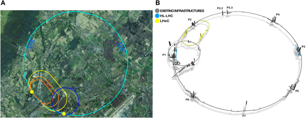
FIGURE 2. (A) Layout options and footprint of the LHeC in the Geneva basin next to the Geneva airport and CERN. The yellow racetrack corresponds to the LHeC layout that offers optimal performance; in orange, two size variations explored for cost optimization. For reference, the light blue circle depicts the existing tunnel of the LHC; the dark blue circle is the SPS. (B) 3D schematic showing the underground tunnel arrangement. The grey sections indicate the existing SPS and LHC tunnel infrastructures and the yellow section the new LHeC installation.
The current LHC planning foresees to extend operation until about 2041 and foresees in total six running periods and five long shutdowns. The nominal LHC operation started in 2010 and extends over three running periods: Run 1 from 2010 until end 2012, Run 2 from 2015 until 2018 and Run three from 2022 until 2025 inclusively. Long Shutdown 1 lasted 2 years from 2013 until 2014 and was used for the consolidation of the inter-magnet splices in order to allow the operation at nominal beam energy of 7 TeV. The second Long Shutdown lasted 3 years and was used for the repair of the diode installation that limited the magnet training after LS1 and the implementation of the LHC Injector Upgrade project. The third LHC run starts in 2022 and is scheduled to extend until 2025 inclusive. A third Long Shutdown extending from 2026 until 2028 will be used for the implementation of the HL-LHC upgrade and the HL-LHC exploitation is assumed to start with Run 4 in 2029. Assuming a 2 year long Long Shutdown 4, the connection of LHeC accelerator complex and the installation of the new LHeC detector could be envisaged during the Long Shutdown 4 in a configuration which may take alternating data on lepton-hadron and on hadron-hadron, as has very recently been shown [74]. For the estimate of the total LHeC performance reach of an integrated luminosity of 1 ab−1 it is assumed that the LHeC operates for two runs in parallel with the HL-LHC exploitation followed by one run in a dedicated operation mode where the operation does no longer have to be assumed to be parasitical to the HL-LHC operation and where the machine performance can be pushed to the maximum value possible. Table 1 summarizes the parameters and performance reach of the different operation phases for the LHeC [5].
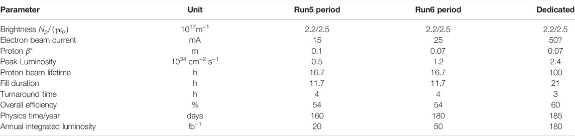
TABLE 1. The LHeC performance levels during different operation modes.
The same machine layout can be used in combination with the HE-LHC, a potential successor project of the HL-LHC that is being studied within the framework of the CERN FCC study. The HE-LHC would use the same tunnel as the LHC and HL-LHC, but would replace the existing superconducting magnets with more powerful high field magnets while using as much as possible the existing LHC infrastructure.
Previous superconducting ERL demonstrators have shown the operability of single-turn, low current ERLs with a maximum beam power of the order of 1 MW. Vital steps for the LHeC development are therefore the demonstration of multi-turn ERL operation with high beam current in the SRF structures and efficient energy recovery and operation efficiency at high beam powers. All three aspects will be addressed with the PERLE ERL demonstrator [75].
6 FCC-eh
The modular design feature of a racetrack shaped ERL that is located tangential to a circular collider, also allows the same design concept (and potentially even the same machine hardware if the projects are staged as separate operation phases) of the LHeC to be used for providing electron-hadron collisions with one of the hadron beams of the FCC-hh [73]. Figure 3 shows the corresponding machine layout for the FCC-eh implementation. The FCC-eh configuration allows a further push of the center of mass collision energy from the 1.2 TeV at the LHeC to 3.5 TeV when colliding the electron beam from the ERL with one of the hadron beams of the FCC-hh machine. The preferred interaction point for such electron-hadron collisions at the FCC complex is the “L” interaction point close to the main CERN site.
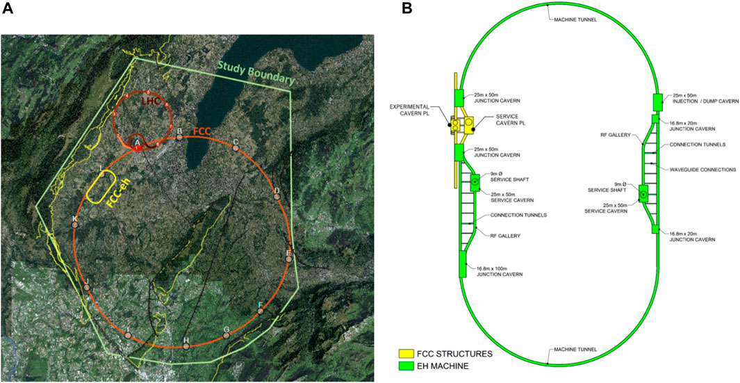
FIGURE 3. FCC-eh layout and underground structures of the FCC-eh. (A) The FCC-eh layout next to the FCC and LHC infrastructures. The yellow lines indicate the ERL of the FCC-eh, the light red lines the FCC installation and the dark red the existing LHC tunnel. (B) Schematic layout of the ERL underground structures for the FCC-eh.
Assuming a staged implementation of the FCC project that starts with a lepton collider in a first phase and a hadron collider in a second phase within the same underground infrastructure could also lead to a scenario where the ERL complex is first used as an injector for the lepton beams for the FCC-ee phase with full energy top-up injection capability for the FCC-ee machine up to the W collision energy, thus sparing the otherwise required booster accelerator within the FCC tunnel. In the second phase of the FCC exploitation with hadron collisions, the ERL complex could then be reconfigured as the electron beam accelerator for electron-hadron collisions during the FCC-hh exploitation phase. Such a staged installation of, first LHeC, followed by an FCC-ee machine with the LHeC ERL [operated in recirculating linac mode without energy recovery] as injector for the lepton beams, followed by an FCC-hh machine with the ERL accelerator providing leptons for lepton-hadron collisions at the FCC represents an interesting scenario for a full exploitation of the infrastructures from the LHC and FCC complex. In addition to providing a unique tool for searching for physics beyond the Standard Model and conducting high precision Higgs studies, the LHeC and FCC-eh provide the finest electron microscope with resolutions of the proton structure down to 10–4 fm and 10–5 fm, respectively, for the LHeC and the FCC-eh cases, respectively. Figure 4 shows the potential resolution within reach with the LHeC and FCC-eh colliders in comparison with the achieved resolution in previous experiments. Table 2 summarizes main design parameters of HERA, EIC, LHeC and FCC-eh.
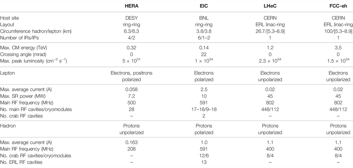
TABLE 2. Parameter comparison for past and designed electron-hadron colliders. The EIC, LHeC and FCC-eh also include an electron-ion program. Additional parameters can be found in Refs. 5, 8, 58, and 73.
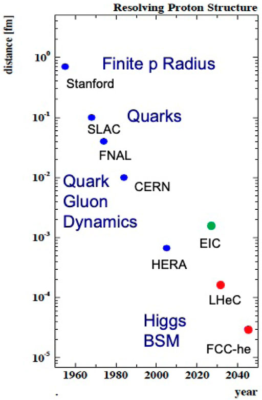
FIGURE 4. Resolving the proton structure: EIC marked in green with spin resolution and the LHeC and FCC-eh colliders marked in red as potential future colliders [76]. The resolving power is directly related to the maximum 1/Q2 achievable at the respective facility. Note: Q2 is the square of the momentum transferred by the electron to the proton.
7 Conclusion
The future electron-hadron colliders EIC, LHeC and FCC-eh draw on the experience of the first and only of their kind, HERA, and will build upon RHIC and LHC, two hadron colliders with exceptional versatility and outstanding performances. The urge to produce efficient machines makes the ERL concept an interesting option for future colliders, to the extent that an ERL is part of the hadron cooler system for the EIC and of the acceleration system for the electron beams in LHeC and FCC-eh. In this way the EIC could become the first collider to include an ERL to support regular operations. The PERLE demonstrator will further demonstrate the efficiency and operability of multi-turn high intensity ERLs over the coming years. The quest for high luminosity also requires that future electron-hadron colliders implement crab crossing and guarantee sufficient beam cooling. The solutions implemented to tackle the challenges presented by these high efficiency, high throughput, versatile colliders will be a lodestar to the next generation of particle colliders. A future polarized spin and heavy ion collider, the EIC, and energy frontier electron-hadron colliders, the LHeC and FCC-eh, represent an exciting prospect for novel, luminous deep-inelastic scattering colliders and experiments, to resolve the substructure and dynamics of matter deeper than hitherto and to contribute to the development of particle and nuclear physics with discoveries in the decades ahead.
Author Contributions
OB, AS, and SV-A contributed in equal parts to the writing and revision of the manuscript. SV-A edited the last version of the manuscript, which was read and approved by OB and AS.
Funding
This study received funding from the Office of Nuclear Physics in the United States Department of Energy (DoE’s) Office of Science under contract DE-AC05-06OR23177 with Jefferson Science Associates, LLC and under contract No. DE-SC0012704 with Brookhaven Science Associates, LLC. This study also received funding from CERN for the LHeC and the FCC-eh studies. The funders were not involved in the study design, collection, analysis, interpretation of data, the writing of this article or the decision to submit it for publication.
Conflict of Interest
AS is employed by Jefferson Science Associates, LLC and SV-A is employed by Brookhaven Science Associates, LLC.
The remaining authors declare that the research was conducted in the absence of any commercial or financial relationships that could be construed as a potential conflict of interest.
Publisher’s Note
All claims expressed in this article are solely those of the authors and do not necessarily represent those of their affiliated organizations, or those of the publisher, the editors and the reviewers. Any product that may be evaluated in this article, or claim that may be made by its manufacturer, is not guaranteed or endorsed by the publisher.
Acknowledgments
We would like to thank Angelika Drees, Christoph Montag, Kevin Smith, Erdong Wang, Ferdinand Willeke, Holger Witte, Binping Xiao (BNL), Jiquan Guo, and Bob Rimmer (JLAB) for assistance to gather updated information about the EIC and for fruitful discussions about HERA and the EIC. We are also thankful to Max Klein (CERN and University of Liverpool) who provided details and materials about the LHeC design. We are grateful to Max Klein (CERN and University of Liverpool), Elke-Caroline Aschenauer (BNL), and Todd Satogata (JLab) who kindly reviewed an earlier version of the manuscript and provided useful suggestions to improve the quality and readability of the manuscript.
References
1. Hofstadter R. Electron Scattering and Nuclear Structure. Rev Mod Phys (1956) 28:214–54. doi:10.1103/revmodphys.28.214
2. Aad G, Abajyan T, Abbott B, Abdallah J, Abdel Khalek S, Abdelalim A, et al. Observation of a New Particle in the Search for the Standard Model Higgs Boson with the ATLAS Detector at the LHC. Phys Lett B (2012) 716:1–29. doi:10.1016/j.physletb.2012.08.020
3. Chatrchyan S, Khachatryan V, Sirunyan A, Tumasyan A, Adam W, Aguilo E, et al. Observation of a New Boson at a Mass of 125 GeV with the CMS experiment at the LHC. Phys Lett B (2012) 716:30–61.
4. Aschenauer EC, Aidala C, Bazilevsky A, Diehl M, Fatemi R, Gagliardi C, et al. The RHIC Cold QCD Plan for 2017 to 2023: A Portal to the EIC (2016). Available at: https://arxiv.org/pdf/1602.03922.pdf (Last Accessed April 4, 2022).
5. Agostini P, Aksakal H, Alekhin S, Allport PP, Andari N, Andre KDJ, et al. The Large Hadron–Electron Collider at the HL-LHC. J Phys G: Nucl Part Phys (2021) 48:110501. doi:10.1088/1361-6471/abf3ba
6. Accardi A. Electron Ion Collider: The Next QCD Frontier: Understanding the Glue that Binds Us All. Eur Phys J A (2016) 52:268. doi:10.1140/epja/i2016-16268-9
7.National Academies of Sciences. Engineering, and Medicine. An Assessment of U.S.-Based Electron-Ion Collider Science. Washington, DC: The National Academies Press (2018). doi:10.17226/25171
8. Voss GA, Wiik BH. The Electron-Proton Collider HERA. Annu Rev Nucl Part Sci (1994) 44:413–52. doi:10.1146/annurev.ns.44.120194.002213
9. Brinkmann R, Willeke F. First Experience with Colliding Electron-Proton Beams in HERA. Proc Int Conf Part Acc (1993) 5:3742–4. doi:10.1109/PAC.1993.309774
10. Schmüser P, Willeke F. The Electron-Proton Collider HERA. Elem Particles (Springer) Landolt-Boernstein—Numerical Data Funct Relationships Sci Tech (2013) 21C:1041–56. New Series.
11. Balewski K, Degele D, Horlitz G, Kaiser H, Lierl H, Mess K-H, et al. Cold Yoke Dipole Magnets for HERA. IEEE Trans Magn (1987) 23:1233–5. doi:10.1109/TMAG.1987.1065098
12. Willeke F, Zimmermann F. The Impact of Persistent Current Field Errors on the Stability of the Proton Beam in the HERA Proton Ring. Conf Rec 1991 IEEE Part Accelerator Conf (1991) 4:2483–7. doi:10.1109/PAC.1991.165007
13. Dwersteg B, Ebeling W, Moller WD, Proch D, Renken D, Sekutowicz J, et al. Superconducting Cavities for HERA. In: Proceedings of the 3rd Workshop on RF Superconductivity (1988). p. 81–94.
15. Parker B, Anerella M, Escallier J, Ghosh A, Jain A, Marone A, et al. Bnl Direct Wind Superconducting Magnets. IEEE Trans Appl Supercond (2012) 22:4101604. doi:10.1109/TASC.2011.2175693
16. Blaskiewicz M. Cooling of High-Energy Hadron Beams. Annu Rev Nucl Part Sci (2014) 64:299–317. doi:10.1146/annurev-nucl-102313-025427
17. Fedotov AV, Altinbas Z, Belomestnykh S, Ben-Zvi I, Blaskiewicz M, Brennan M, et al. Experimental Demonstration of Hadron Beam Cooling Using Radio-Frequency Accelerated Electron Bunches. Phys Rev Lett (2020) 124:084801. doi:10.1103/PhysRevLett.124.084801
18. Fischer W. Run Overview of the Relativistic Heavy Ion Collider (2022). https://www.rhichome.bnl.gov/RHIC/Runs/ (Last Accessed December 2, 2022).
19.N Mounet, editor. European Strategy for Particle Physics - Accelerator RD Roadmap. Monographs: CERN Yellow Reports (2021). doi:10.23731/CYRM-2022-001
20.Snowmass 2021. Accelerator Frontier (2021). Available at: https://snowmass21.org/accelerator/ (Last Accessed April 4, 2022).
21. Abelleira-Fernandez JL, Adolphsen C, Akay A, Aksakal H, Albacete J, Alekhin S, et al. A Large Hadron Electron Collider at CERN. J Phys G: Nucl Part Phys (2012) 39:075001. doi:10.1088/0954-3899/39/7/075001
22. Temple E. NSAC Sub-committee Review of the EIC (Electron Ion Collider) Cost Estimates (2015). Available at: https://science.osti.gov/-/media/np/nsac/pdf/20150403 (Last Accessed April 4, 2022).
23. Tigner M. A Possible Apparatus for Electron Clashing-Beam Experiments. Nuovo Cim (1965) 37:1228–31. doi:10.1007/bf02773204
24. Grassellino A, Romanenko A, Sergatskov D, Melnychuk O, Trenikhina Y, Crawford A, et al. Nitrogen and Argon Doping of Niobium for Superconducting Radio Frequency Cavities: a Pathway to Highly Efficient Accelerating Structures. Supercond Sci Technol (2013) 26:102001. doi:10.1088/0953-2048/26/10/102001
25. Grassellino A, Romanenko A, Trenikhina Y, Checchin M, Martinello M, Melnychuk OS, et al. Unprecedented Quality Factors at Accelerating Gradients up to 45 MVm−1in Niobium Superconducting Resonators via Low Temperature Nitrogen Infusion. Supercond Sci Technol (2017) 30:094004. doi:10.1088/1361-6668/aa7afe
26. Dhakal P. Nitrogen Doping and Infusion in SRF Cavities: A Review. Phys Open (2020) 5:100034. doi:10.1016/j.physo.2020.100034
27. Ganni V. Helium Refrigeration Systems for Super-conducting Accelerators. AIP Conf Proc (2015) 1687:040001. doi:10.1063/1.4935327
28. Posen S, Hall DL. Nb3Sn Superconducting Radiofrequency Cavities: Fabrication, Results, Properties, and Prospects. Supercond Sci Technol (2017) 30:033004. doi:10.1088/1361-6668/30/3/033004
29. Dunham B, Barley J, Bartnik A, Bazarov I, Cultrera L, Dobbins J, et al. Record High-Average Current from a High-Brightness Photoinjector. Appl Phys Lett (2013) 102:034105. doi:10.1063/1.4789395
30. Petrushina I, Litvinenko VN, Jing Y, Ma J, Pinayev I, Shih K, et al. High-brightness Continuous-Wave Electron Beams from Superconducting Radio-Frequency Photoemission Gun. Phys Rev Lett (2020) 124:244801. doi:10.1103/physrevlett.124.244801
31. Wang E, Litvinenko VN, Pinayev I, Gaowei M, Skaritka J, Belomestnykh S, et al. Long Lifetime of Bialkali Photocathodes Operating in High Gradient Superconducting Radio Frequency Gun. Sci Rep (2021) 11:4477. doi:10.1038/s41598-021-83997-1
32. Maruyama T, Garwin EL, Prepost R, Zapalac GH, Smith JS, Walker JD. Observation of Strain-Enhanced Electron-Spin Polarization in Photoemission from InGaAs. Phys Rev Lett (1991) 66:2376–9. doi:10.1103/PhysRevLett.66.2376
33. Liu W, Chen Y, Lu W, Moy A, Poelker M, Stutzman M, et al. Record-level Quantum Efficiency from a High Polarization Strained GaAs/GaAsP Superlattice Photocathode with Distributed Bragg Reflector. Appl Phys Lett (2016) 109:252104. doi:10.1063/1.4972180
34. Piwinski A. Storage Ring Luminosity as a Function of Beam-To-Beam Space and Crossing Angle (1967).
35. Abe T. Beam Operation with Crab Cavities at KEKB. Conf Proc C (2007) 070625:1487. doi:10.1109/PAC.2007.4440798
36. Funakoshi Y. Operational Experience with Crab Cavities at KEKB. In: W Herr, and G Papotti, editors. Proceedings of the ICFA Mini-Workshop on Beam–Beam Effects in Hadron Colliders. CERN–2014–004 (2014). p. 27–36. doi:10.5170/CERN--2014--004.27
37. Calaga R, Tomas R, Zimmermann F. Crab Cavity Option for LHC IR Upgrade. In: W Scandale, T Taylor, and F Zimmermann, editors. 3rd CARE-HHH-APD Workshop: Towards a Roadmap for the Upgrade of the LHC and GSI Accelerator Complex: Valencia, Spain 16 - 20 Oct 2006. CERN. Geneva: CERN (2007). doi:10.5170/CERN-2007-002
38. Calaga R, Alekou A, Antoniou F, Appleby RB, Arnaudon L, Artoos K, et al. First Demonstration of the Use of Crab Cavities on Hadron Beams. Phys Rev Accel Beams (2021) 24:062001. doi:10.1103/PhysRevAccelBeams.24.062001
40. Sun Y-P, Assmann R, Barranco J, Tomás R, Weiler T, Zimmermann F, et al. Beam Dynamics Aspects of Crab Cavities in the CERN Large Hadron Collider. Phys Rev ST Accel Beams (2009) 12:101002. doi:10.1103/PhysRevSTAB.12.101002
41. Xu D, Hao Y, Luo Y, Qiang J. Synchrobetatron Resonance of Crab Crossing Scheme with Large Crossing Angle and Finite bunch Length. Phys Rev Accel Beams (2021) 24:041002. doi:10.1103/PhysRevAccelBeams.24.041002
42. Calaga R, De Maria R, Metral E, Sun Y, Tomas R, Zimmermann F. Crab Cavities. In: Proceedings of the Chamonix 2010 Workshop on LHC Performance (2010).
43. Xiao B, Alberty L, Belomestnykh S, Ben-Zvi I, Calaga R, Cullen C, et al. Design, Prototyping, and Testing of a Compact Superconducting Double Quarter Wave Crab Cavity. Phys Rev ST Accel Beams (2015) 18:041004. doi:10.1103/PhysRevSTAB.18.041004
44. Verdú-Andrés S, Artoos K, Belomestnykh S, Ben-Zvi I, Boulware C, Burt G, et al. Design and Vertical Tests of Double-Quarter Wave Cavity Prototypes for the High-Luminosity LHC Crab Cavity System. Phys Rev Accel Beams (2018) 21:082002. doi:10.1103/PhysRevAccelBeams.21.082002
45. De Silva SU, Delayen JR. Design Evolution and Properties of Superconducting Parallel-Bar Rf-Dipole Deflecting and Crabbing Cavities. Phys Rev ST Accel Beams (2013) 16:012004. doi:10.1103/PhysRevSTAB.16.012004
46. De Silva SU, Delayen JR. Cryogenic Test of a Proof-Of-Principle Superconducting Rf-Dipole Deflecting and Crabbing Cavity. Phys Rev ST Accel Beams (2013) 16:082001. doi:10.1103/PhysRevSTAB.16.082001
47. Hall B, Burt G, Apsimon R, Lingwood CJ, Tutte A, Grudiev A, et al. Design and Testing of a Four Rod Crab Cavity for High Luminosity LHC. Phys Rev Accel Beams (2017) 20:012001. doi:10.1103/PhysRevAccelBeams.20.012001
48. Blaskiewicz M. Instabilities Driven by the Fundamental Crabbing Mode. Tech. Rep. Upton, NY, United States: Brookhaven National Laboratory (2021). doi:10.2172/1825736Instabilities Driven by the Fundamental Crabbing Mode
49. Smith K, Mastoridis T, Fuller P, Mahvi P, Matsumara Y. EIC Transverse Emittance Growth Due to Crab Cavity RF Noise: Estimates and Mitigation. Tech. Rep. Upton, NY, United States: Brookhaven National Laboratory (2022).
51. Wei G, Morozov V, Zhang Y, Pilat FC. Evaluation and Compensation of Detector Solenoid Effects in the JLEIC. In: Proc. 7th Int. Particle Accelerator Conf. (IPAC’16). Busan, Korea (2016). p. 2454–6. doi:10.18429/JACoW-IPAC2016-WEPMW015
52. Gamage BR, Michalski TJ, Morozov VS, Rajput-Ghoshal R, Seryi A, Wittmer W, et al. Detector Solenoid Compensation for the Electron-Ion Collider. Proc 12th Int. Part Acc. Conf. (2021). doi:10.18429/JACoW-IPAC2021-TUPAB041
53. Berg JS. First IR DesignEIC Workshop – Accelerator Partnerships (2021). Available at: https://meetings.triumf.ca/event/254/ (Last Accessed April 4, 2022).
54. Willeke F. The HERA Lepton-Proton Collider. chap (2016) 15:225–42. doi:10.1142/9789814436403_0015
55. Schneekloth U. The HERA Ep Interaction Regions Learned Lessons. Electron-Ion Collider Workshop (2008). https://web.mit.edu/eicc/Hampton08/ (Last Accessed April 4, 2022).
56. Stutzman M. Interaction Region, Synchrotron Radiation and Vacuum EIC Workshop – Accelerator Partnerships (2021). Available at: https://meetings.triumf.ca/event/254/ (Last Accessed April 4, 2022).
58. Willeke F, Beebe-Wang J. Upton, NY, United States: Brookhaven National Laboratory (2021). doi:10.2172/1765663Electron Ion Collider Conceptual Design Report 2021Tech Rep
59. Montag C. Design Status Update of the Electron-Ion Collider. JACoW. Proc 12th Int Part. Acc Conf (Jacow) (2021) 2585–8. doi:10.18429/JACoW-IPAC2021-WEPAB005
60. Xu W, Fite J, Holmes D, Conway Z, Smith K, Zaltsman A. High Power Coupler Development for EIC. In: Proc. 2021 International Conference on RF Superconductivity (SRF’21) (2021). doi:10.2172/1809066
61. Fischer W, Blaskiewicz M, Brennan M, Huang H, Hseuh H-C, Ptitsyn V, et al. Electron Cloud Observations and Cures in RHIC. In: Proc. 22nd Particle Accelerator Conference (PAC). Albuquerque, New Mexico: JACoW (2007). p. 759–63. doi:10.1109/PAC.2007.4441092
62. Verdú-Andrés S, Brennan J, Blaskiewicz X, Mand G, Gupta R, Hershcovitch A, et al. A Beam Screen to Prepare the RHIC Vacuum Chamber for EIC Hadron Beams: Conceptual Design and Requirements. JACoW. In: Proc. 12th Int. Particle Acc. Conf. São Paulo, Brazil: JACoW (2021). p. 2066–9. doi:10.18429/JACoW-IPAC2021-TUPAB260
63. Yin Vallgren C, Arduini G, Bauche J, Calatroni S, Chiggiato P, Cornelis K, et al. Amorphous Carbon Coatings for the Mitigation of Electron Cloud in the CERN Super Proton Synchrotron. Phys Rev ST Accel Beams (2011) 14:071001. doi:10.1103/PhysRevSTAB.14.071001
64. Rimmer R, Preble J, Smith K, Zaltsman A. HOM Damper Design for BNL EIC 197 MHz Crab Cavity. JACoW. In: Proc. 12th Int. Particle Acc. Conf. São Paulo, Brazil: JACoW (2021). p. 1179–81.
65.Preble J. EIC RF Systems Overview. EIC Workshop – Accelerator Partnerships (2021). Available at: https://meetings.triumf.ca/event/254/.
66. Xiao B, Delayen J, De Silva SU, Li Z, Rimmer R, Verdú-Andrés S, et al. HOM Damper Design for BNL EIC 197 MHz Crab Cavity. JACoW. In: Proc. 2021 International Conference on RF Superconductivity. Grand Rapids, MI, United States: JACoW (2021).
67. Stupakov G. Micro-bunched Electron Cooling (MBEC) for Future Electron-Ion Colliders. In 61st ICFA ABDW on High-Intensity and High-Brightness Hadron Beams. Daejeon, Korea: JACoW (2018). p. 379–81.
68. Wang E. The Accelerator Design Progress for EIC strong Hadron Cooling. JACoW. In: 12th Int. Particle Acc. Conf. São Paulo, Brazil: JACoW (2021). p. 1424–7.
69. Ratner D. Microbunched Electron Cooling for High-Energy Hadron Beams. Phys Rev Lett (2013) 111:084802. doi:10.1103/PhysRevLett.111.084802
70. Witte H, Parker B, Palmer R. Design of a Tapered Final Focusing Magnet for eRHIC. IEEE Trans Appl Supercond (2019) 29:1–5. doi:10.1109/TASC.2019.2902982
71. Hallman T. DOE NP Perspectives on the Electron-Ion Collider (EIC) (2021). EIC Workshop – Accelerator Partnerships. Available at: https://meetings.triumf.ca/event/254/ (Last Accessed April 4, 2022).
72. Abada A, Abbrescia M, AbdusSalam SS, Abdyukhanov I, Abelleira Fernandez J, Abramov A, et al. HE-LHC: The High-Energy Large Hadron Collider. Eur Phys J Spec Top (2019) 228:1109–382. doi:10.1140/epjst/e2019-900088-6
73. Abada A, Abbrescia M, AbdusSalam SS, Abdyukhanov I, Abelleira Fernandez J, Abramov A, et al. FCC-hh: The Hadron Collider. Eur Phys J Spec Top (2019) 228:755–1107. doi:10.1140/epjst/e2019-900087-0
74. André KDJ, Bella LA, Armesto N, Bogacz SA, Britzger D, Brüning OS, et al. An experiment for Electron-Hadron Scattering at the LHC. Eur Phys J C (2022) 82:40. doi:10.1140/epjc/s10052-021-09967-z
75. Klein M, Stocchi A. PERLE: A High Power Energy Recovery Facility for Europe. A Contribution to the Update of the European Strategy on Particle Physics (2018).
Keywords: electron, hadron, collider, proton, ion
Citation: Brüning O, Seryi A and Verdú-Andrés S (2022) Electron-Hadron Colliders: EIC, LHeC and FCC-eh. Front. Phys. 10:886473. doi: 10.3389/fphy.2022.886473
Received: 28 February 2022; Accepted: 06 April 2022;
Published: 25 April 2022.
Edited by:
Vladimir Shiltsev, Fermi National Accelerator Laboratory (DOE), United StatesReviewed by:
Matthew Wing, University College London, United KingdomAllen Caldwell, Max Planck Society, Germany
Copyright © 2022 Brüning, Seryi and Verdú-Andrés. This is an open-access article distributed under the terms of the Creative Commons Attribution License (CC BY). The use, distribution or reproduction in other forums is permitted, provided the original author(s) and the copyright owner(s) are credited and that the original publication in this journal is cited, in accordance with accepted academic practice. No use, distribution or reproduction is permitted which does not comply with these terms.
*Correspondence: Oliver Brüning, T2xpdmVyLkJydW5pbmdAY2Vybi5jaA==; Andrei Seryi, c2VyeWlAamxhYi5vcmc=; Silvia Verdú-Andrés, c3ZlcmR1QGJubC5nb3Y=
†These authors have contributed equally to this work and share first authorship