 Yuqiu Zhang
 Tianyue Hou
 Yu Deng
94% of researchers rate our articles as excellent or good
Learn more about the work of our research integrity team to safeguard the quality of each article we publish.
Find out more
ORIGINAL RESEARCH article
Front. Phys., 06 April 2022
Sec. Optics and Photonics
Volume 10 - 2022 | https://doi.org/10.3389/fphy.2022.880436
This article is part of the Research TopicFuture Directions in Novel Laser Source Development: Dynamical Properties, and Beam ManipulationView all 14 articles
The influence of thermal blooming on the propagation properties of higher-order mode (HOM) fiber laser array is studied by using the algorithm for simulating the laser beam propagation in the atmosphere. Based on the multiphase screen method and finite-difference method, the four-dimensional (4D) computer code of time-dependent propagation is designed to simulate the propagation of HOM fiber laser array through the atmosphere. In this study, the laser energy focusability of the LP11 mode beam array is investigated in detail for different beamlet arrangements, transverse wind speed, and the content of LP01 mode under the conditions of thermal blooming. In free space, the focal shape of the LP11 mode beam array depends on the arrangement of the second circle of the initial beam array, whereas the influence of the central beamlets is weak. The number of side lobes can be tailored by changing the arrangement of the beamlets. In contrast, under the conditions of thermal blooming, the central beamlet has a significant effect on focal beam shape. It is demonstrated that the laser energy focusability can be improved by rotating the central beamlet or increasing the transverse wind speed. As the content of the LP01 mode increases, the energy is gradually concentrated from the side lobes to the center lobe. Furthermore, the effects of initial beam array arrangements on the energy focus and focal shape are investigated. The optimal arrangement for obtaining high energy focusability is discussed in detail. These results could provide useful references for applications of the HOM beam array.
The large mode area (LMA) fiber is remarkable for its advantages in suppressing a number of nonlinear effects [1–3]. In recent years, higher-order modes (HOMs) with specific spatial intensity, phase, and polarized distributions have been widely applied in many practical applications, such as optical tweezers, optical communication, micro-machining, and material processing [4–8]. Driven by these demanding applications, the methods of generating HOMs in fiber lasers have been demonstrated widely [9–12]. HOMs can be generated based on the active mode control system, and various methods have been successfully demonstrated, including spatial light modulator (SLM) [13], long-period fiber gratings [14, 15], fiber Bragg grating [16], random fiber lasers [17], polarization control [18, 19], and mode-selective couplers (MSCs) [20, 21]. Notably, You et al. demonstrated a kilowatt (kW)-level HOM laser beam based on the master oscillator power amplifier (MOPA) configuration [22]. These advancements of HOMs can be beneficial for further power scaling.
The power scaling of the output laser beyond the kilowatt (kW) level can be achieved by the coherent beam combining (CBC) technology as well [23–25]. In last decades, the coherent combining of laser beams has been widely used in high-power systems and inertial confinement fusion due to the advantages such as efficiency, compactness, and reliability [26–28]. Recently, high output power [29–31] and a large number of channels [32, 33] based on the coherent combining of the fiber amplifier array have been reported. In addition, the structured light beams can also be generated from the beam array [34]. Until now, various structured light beams based on CBC technology have been demonstrated theoretically and experimentally [35–38].
When a high-power laser beam propagates through the atmosphere, the propagation characteristics of the laser beam could be affected by nonlinear effects such as thermal blooming, self-focusing, stimulated Raman scattering, and etc. The thermal blooming effect is one of the most important nonlinear effects, which is caused by the energy of the laser beam absorbed by molecules and aerosols in the atmosphere [39]. Thermal blooming leads to decreasing of the peak irradiance, and the presence of a transverse wind will further cause the shift of the peak irradiance, which will result in the degradation of beam quality and limit the use of high-power laser delivery [40, 41]. Over the last decades, the study of the effect of thermal blooming on high-power laser beams propagating in the atmosphere has gained considerable attention. For example, Gebhardt and Smith developed a theoretical model to predict thermal blooming distortion in the atmosphere [42]. Fleck et al. proposed a four-dimensional (4D) computer code of the time-dependent propagation of high-power laser beams to investigate the thermal blooming effect [43]. Moreover, the effect of thermal blooming on annular beams, airy beams, Hermite–Gaussian beams, and vortex beams has been studied in detail [44–47]. With the development of the CBC technology, the studies of the effect of thermal blooming on the beam array have also been carried out in recent years [48–51]. To the best of our knowledge, the effect of thermal blooming on the HOM beam array has not been investigated yet.
The aim of the study is to study the influence of thermal blooming on the propagation properties of a coherent beam combined with the high-power continuous wave HOM beam array in the atmosphere. The mathematical model of the HOM beam array and 4D computer algorithms are presented in the Theoretical Model section. The LP11 mode beam array is considered in this study. In the Numerical Simulations Results and Analysis section, the changes of focal shape in free space for different beamlet arrangements are studied. In addition, the influence of the beamlet arrangement and content of the LP01 mode on the energy focusability under the conditions of thermal blooming is investigated in detail. In the Conclusion section, the main results obtained in this study are summarized.
At present, the step-index fiber is taken as the gain medium for most high-power fiber laser systems. Without loss of generality, the HOMs excited from a step-index fiber is investigated in this study. It is considered that the coordinate z-axis is parallel to the geometrical axis of the fiber with the core radius a. In the weakly guiding approximation, the field distribution of the LPnm-mode can be expressed as [52].
where
where
and
The normalized frequency V is defined as
where ncore and nclad are the core refractive index and cladding refractive index, respectively. The numerical aperture (NA) can be written as
The HOMs excited in the fiber are magnified 200 times by a large diameter collimator and then combined in the beam combiner system. It is assumed that a HOM beam array consists of seven beamlets located as z = 0, which are arranged in a tiled hexagonal architecture by coherent beam combining, as shown in Figure 1. The distance between the centers of neighboring sub-aperture is r0 and the diameter of the whole beam array is D. The optical field of each beamlet is
where
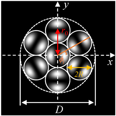
FIGURE 1. Schematic diagram of a HOM beam array.
In the parabolic approximation, the electric field E satisfies the Maxwell wave equation (43).
where
where v, γ, cs, and α are the wind speed, specific heat, sound speed capacity ratio, and absorption coefficient in the atmosphere, respectively. The intensity I is given by
Based on Eqs 1–9, we designed a 4D computer code to simulate the time-dependent propagation of a HOM beam array propagating through the atmosphere by using the multiphase screen method and finite-difference method [43]. A lens with focus zf = 5 km located at z = 0 is considered in this study. In the following calculations, the parameters are taken as a = 50 μm, R = 4.5 cm,
In this section, the propagation properties of the LP11 mode beam array propagating in free space are demonstrated. As we all know, the intensity distribution of the LP01 mode is circular symmetry, and the far field intensity distribution of the LP01 mode coherent beam array is comprises a central lobe with a number of side lobes. But for the LP11 mode, the intensity distribution is axial symmetry, and therefore, the arrangement of the LP11 mode has a significant impact on the focal intensity distributions.
The intensity distributions of the LP11 mode beam array with centrosymmetric arrangement are shown in Figure 2. It is assumed that the angle of the LP11 mode around the central beamlet in Figure 2A is set as θ = 0, and the different rotation angles for the initial beamlet arrangement are shown in Figures 2B–D. It can be seen that the beam shapes of the LP11 mode beam array at the receiver plane are quite different from those of the LP01 mode beam array. The beam shapes of the LP11 mode beam array are a radial spot beam array without a central lobe. As θ changes from 0 to 90°, the number of side lobes gradually changes from 6 to 12. By comparing the beam shapes at the initial plane, it is clearly seen that the focal intensity distributions are consistent with the first ring of the hexagonal mesh of the fiber laser array (see the red circle highlight in Figures 2A–D). These observations indicate that the desired beam shape of the focusing spots can be obtained by simply rotating the surrounding beamlets.
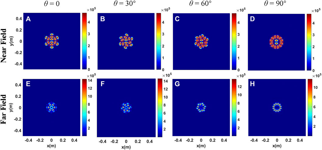
FIGURE 2. Intensity distributions of the LP11 mode beam array for different rotation angles of beamlets. (A–D) Intensity distributions at the initial plane. (E–H) Intensity distributions at the receiver plane in free space.
It can be clearly seen that different focal spots can be obtained by changing the initial arrangement of the LP11 mode beam array as mentioned in the Linear propagation of HOMs beam array section. Therefore, the impact of thermal blooming on the LP11 mode beam array can be quite different for different arrangements. In this section, based on the results in the Linear propagation of HOMs beam array section, the effects of thermal blooming on the special arrangements of the LP11 mode beam array are investigated in detail.
The intensity distributions of the LP11 mode beam array for centrosymmetric arrangement under the conditions of thermal blooming are shown in Figures 3, 4. From Figures 4I–L, it can be observed that the influence of thermal blooming on the LP11 mode beam array can be quite different for different rotation angles. In addition, the focal beam shapes are not symmetrical except for the arrangement of Figure 3A. The difference between Figure 3 and Figure 4 is that the initial central beamlets in Figure 4 are rotated by 90 degrees. It can be seen that the focal beam shapes under thermal blooming are quite different, although the focal beam shapes in free space are the same. The phenomena illustrates that the arrangement of the central beamlet has little influence on the focal beam shapes in free space but has a significant effect on the focal beam shapes under thermal blooming.
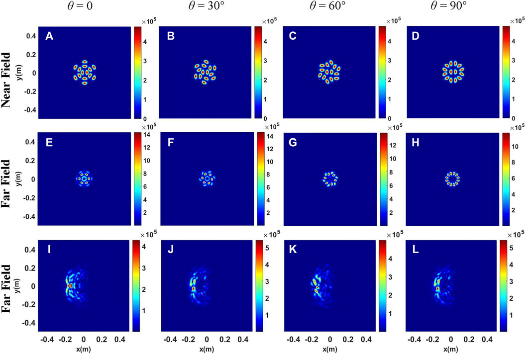
FIGURE 3. Intensity distributions of the LP11 mode beam array for different rotation angles of beamlets. (A–D) Intensity distributions at the initial plane; (E–H) Intensity distributions at the receiver plane in free space; (I–L) Intensity distributions at the receiver plane under thermal blooming.
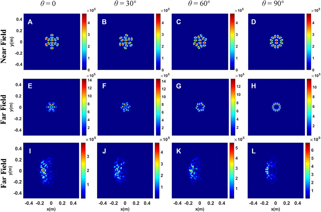
FIGURE 4. Intensity distributions of the LP11 mode beam array with different rotation angles of beamlets. (A–D) Intensity distributions at the initial plane; (E–H) Intensity distributions at the receiver plane in free space; (I–L) Intensity distributions at the receiver plane under thermal blooming.
It is assumed that the directions of the central beamlet in Figures 3A–D are parallel to that of the wind and that in Figures 4A–D are vertical to that of the wind. Generally, the power of the bucket-based beam width is used to describe beam spreading and energy focusability, which is expressed as [55]
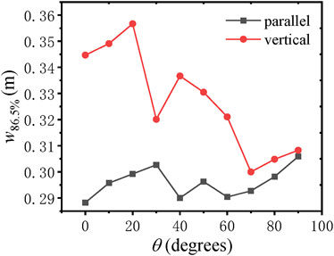
FIGURE 5. Variation of beam width w86.5% with rotating angle θ for different arrangements of the central beamlet.
Here, we choose four arrangement types of initial beamlets (see Figures 6A–D) to investigate the influence of transverse wind speed on the energy focusability. As can be seen from Figure 6E, the beam width decreases and becomes closer as the wind speed increases. The physical reason is that the absorbed energy in the propagation path is carried away more quickly as the wind speed increases. That is to say, increasing the transverse wind speed can help increase the energy focusability. In addition, the beam width of Figure 6A is the largest for different values of wind speed. Thus, the arrangement of Figure 6A should be avoided in order to improve the energy focusability.
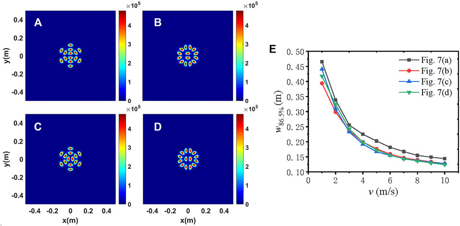
FIGURE 6. (A–D) Intensity distributions of the LP11 mode beam array with different arrangement of beamlets; (E) variation of beam width w86.5% with wind speed v.
In practical applications, it is difficult to obtain the pure LP01 mode even at relatively high conversion efficiency. Therefore, the case of the mixture of LP01 and LP11 modes is worth studying. Considering that the model superposition states comprise different admixtures of the LP01 and LP11 modes, the initial field can be expressed as
where
The intensity distributions of the mixed-mode beam array are shown in Figures 7–9. It can be seen from Figures 7–9 that in free space, as the content of the LP01 mode increases, the energy is gradually concentrated from the side lobes to the center lobe. That is to say, the energy distribution between the central lobe and side lobes can be controlled by changing the content of the LP01 mode. The difference in Figures 7–9 is that the initial arrangement of the outer-ring beamlets is different. As can be seen from Figure 7, the focal beam shape of the pure LP11 mode beam array comprises six radial spots, and the energy is concentrated in the central lobe for the pure LP01 mode beam array.
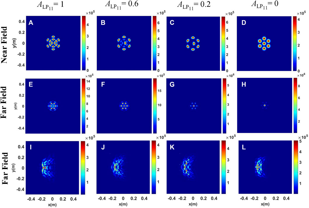
FIGURE 7. Intensity distributions of the mixed-mode beam array for different content of the LP01 mode. (A–D) Intensity distributions at the initial plane; (E–H) Intensity distributions at the receiver plane in free space; (I–L) Intensity distributions at the receiver plane under the conditions of thermal blooming.
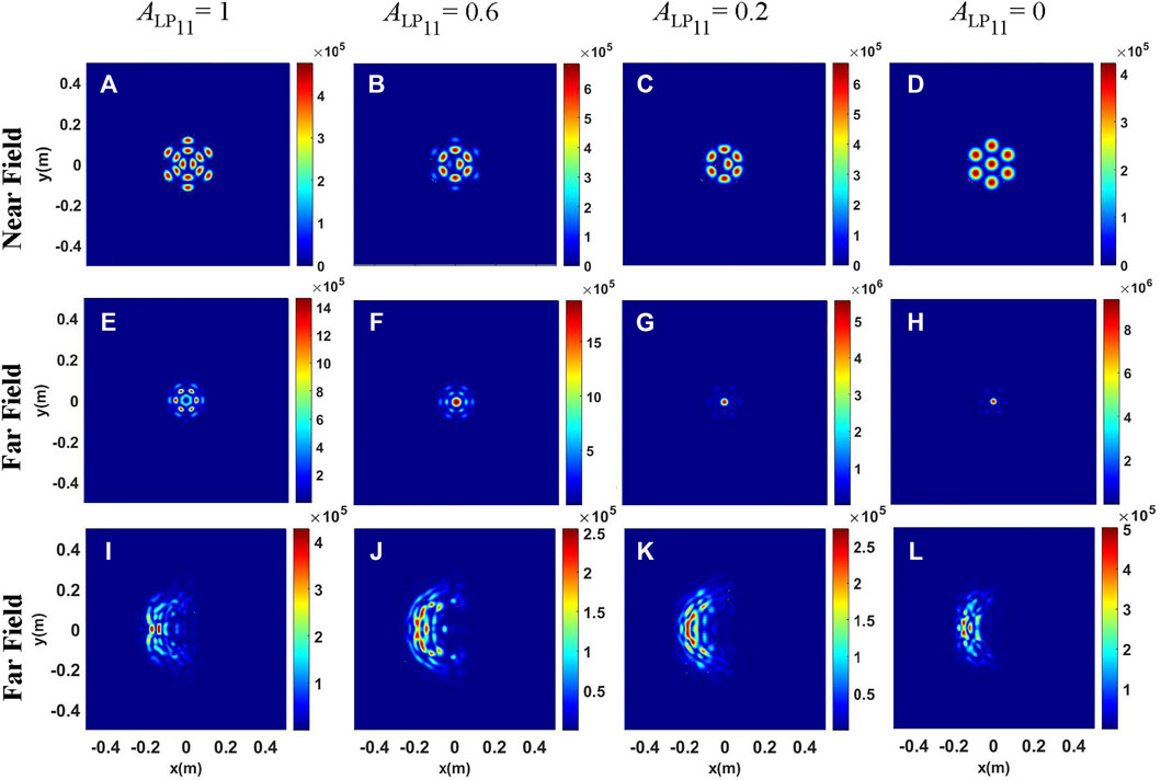
FIGURE 8. Intensity distributions of the mixed-mode beam array for different content of the LP01 mode. (A–D) Intensity distributions at the initial plane; (E–H) Intensity distributions at the receiver plane in free space; (I–L) Intensity distributions at the receiver plane under the conditions of thermal blooming.
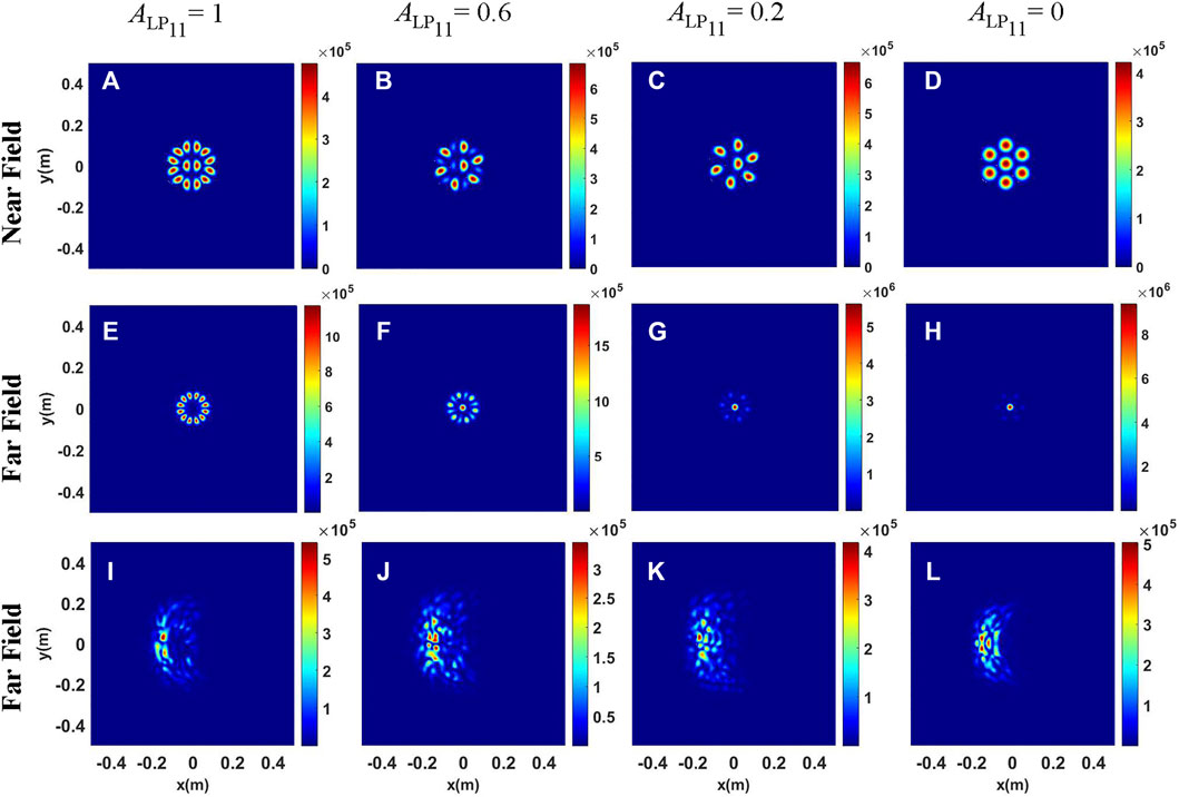
FIGURE 9. Intensity distributions of the mixed-mode beam array for different content of the LP01 mode. (A–D) Intensity distributions at the initial plane; (E–H) Intensity distributions at the receiver plane in free space; (I–L) Intensity distributions at the receiver plane under the conditions of thermal blooming.
As we rotate the outer-ring beamlets 180 degrees on the basis of Figure 7, the intensity distributions of the mixed mode beam array under different conditions are shown in Figure 8. It can be clearly seen that when the mixed-mode beam array propagates in free space, the energy of the central lobe in Figure 8 is more concentrated than that in Figure 7. The physical reason is that the beam distribution at the initial plane is more compact in Figure 8. However, the intensity distributions under thermal blooming in Figure 8 are more dispersive than those in Figure 7. Thus, the arrangements of beamlets at the initial plane in Figure 7 are more resistant to the degrading effect of thermal blooming.
As we rotate the outer-ring beamlets 90 degrees on the basis of Figure 8, the intensity distributions of the mixed-mode beam array under different conditions are shown in Figure 9. As mentioned previously, the focal intensity distribution comprises 12 radial spots when the initial intensity distribution is shown in Figure 9A. However, the number of side lobes decreases as the content of the LP01 mode increases, that is, the side lobes are six when the content of the LP01 mode is 0.6. In order to compare the energy focusability under the three conditions more intuitively, the beam width
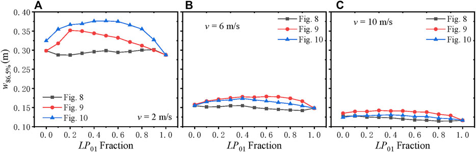
FIGURE 10. Variation of beam width w86.5% with LP01 fraction for different values of wind speeds.
In this study, the propagation properties of high-power HOM beam arrays propagating in the atmosphere are studied in detail. Based on the multiphase screen method and finite-difference method, a 4D computer code of the HOM beam array propagating through the atmosphere under the conditions of thermal blooming is designed. In particular, the LP11 mode is considered in this study. The propagation characteristics of the pure LP11 mode beam array in free space and in the atmosphere are investigated. It has been found that the focal intensity distributions in free space are consistent with the arrangement of the second circle of the initial beam array. The desired beam shape of focusing spots can be obtained by rotating the surrounding beamlets. In addition, the arrangement of the central beamlet has little influence on the focal beam shapes in free space but has a significant effect on the focal beam shapes under the conditions of thermal blooming. Thus, the energy focusability can be improved by rotating the central beamlet. When the transverse wind speed increases, the thermal blooming effect decreases and the energy focusability increases. Moreover, the influence of the content of the LP01 mode is investigated in this study, and three kinds of arrangement of the initial beam array are considered. The results show that as the content of the LP01 mode increases, the energy is gradually concentrated from the side lobes to the center lobe. The energy ratio of the side lobes to the central lobe is related to the initial arrangement. Meanwhile, the energy distribution between the central lobe and side lobes can be controlled by changing the content of the LP01 mode. The condition for obtaining high energy focusability has been discussed in detail. These results obtained in this study are useful for directed-energy applications in the atmosphere.
The original contributions presented in the study are included in the article/Supplementary Material, further inquiries can be directed to the corresponding author.
All authors listed have made a substantial, direct, and intellectual contribution to the study and approved it for publication.
National Natural Science Foundation of China (61705265), and Natural Science Foundation of Hunan province, China (2019JJ10005).
The authors declare that the research was conducted in the absence of any commercial or financial relationships that could be construed as a potential conflict of interest.
All claims expressed in this article are solely those of the authors and do not necessarily represent those of their affiliated organizations, or those of the publisher, the editors, and the reviewers. Any product that may be evaluated in this article, or claim that may be made by its manufacturer, is not guaranteed or endorsed by the publisher.
1. Dong L, Kong F, Gu G, Hawkins TW, Jones M, Parsons J, et al. Large-Mode-Area All-Solid Photonic Bandgap Fibers for the Mitigation of Optical Nonlinearities. IEEE J Select Top Quan Electron. (2016) 22(2):316–22. doi:10.1109/jstqe.2015.2451012
2. Wang L, He D, Yu C, Feng S, Hu L, Chen D. Very Large-Mode-Area, Symmetry-Reduced, Neodymium-Doped Silicate Glass All-Solid Large-Pitch Fiber. IEEE J Select Top Quan Electron. (2016) 22(2):108–12. doi:10.1109/jstqe.2015.2427746
3. Jeong Y, Sahu JK, Payne DN, Nilsson J. Ytterbium-doped Large-Core Fiber Laser with 1.36 kW Continuous-Wave Output Power. Opt Express (2004) 12(25):6088–92. doi:10.1364/opex.12.006088
4. Venkatakrishnan K, Tan B. Generation of Radially Polarized Beam for Laser Micromachining. jlmn (2012) 7(3):274–8. doi:10.2961/jlmn.2012.03.0008
5. Richardson DJ, Fini JM, Nelson LE. Space-division Multiplexing in Optical Fibres. Nat Photon (2013) 7(5):354–62. doi:10.1038/nphoton.2013.94
6. Meier M, Romano V, Feurer T. Material Processing with Pulsed Radially and Azimuthally Polarized Laser Radiation. Appl Phys A (2007) 86(3):329–34. doi:10.1007/s00339-006-3784-9
7. Liu Z, Wang L, Liang P, Zhang Y, Yang J, Yuan L. Mode Division Multiplexing Technology for Single-Fiber Optical Trapping Axial-Position Adjustment. Opt Lett (2013) 38(14):2617–20. doi:10.1364/ol.38.002617
8. Wang J. Advances in Communications Using Optical Vortices. Photon Res (2016) 4(5):B14–B28. doi:10.1364/prj.4.000b14
9. Ramachandran S, Kristensen P, Yan MF. Generation and Propagation of Radially Polarized Beams in Optical Fibers. Opt Lett (2009) 34(16):2525–7. doi:10.1364/OL.34.002525
10. Mao D, Li M, He Z, Cui X, Lu H, Zhang W, et al. Optical Vortex Fiber Laser Based on Modulation of Transverse Modes in Two Mode Fiber. APL Photon (2019) 4(6):060801. doi:10.1063/1.5094599
11. Lin D, Daniel JMO, Gecevičius M, Beresna M, Kazansky PG, Clarkson WA. Cladding-pumped Ytterbium-Doped Fiber Laser with Radially Polarized Output. Opt Lett (2014) 39(18):5359–61. doi:10.1364/OL.39.005359
12. Mao D, Zheng Y, Zeng C, Lu H, Wang C, Zhang H, et al. Generation of Polarization and Phase Singular Beams in Fibers and Fiber Lasers. Adv Photon (2021) 3(1):014002. doi:10.1117/1.Ap.3.1.014002
13. Lin D, Carpenter J, Feng Y, Jain S, Jung Y, Feng Y, et al. Reconfigurable Structured Light Generation in a Multicore Fibre Amplifier. Nat Commun (2020) 11(1):3986. doi:10.1038/s41467-020-17809-x
14. Liu T, Chen S, Qi X, Hou J. High-power Transverse-Mode-Switchable All-Fiber Picosecond MOPA. Opt Express (2016) 24(24):27821–7. doi:10.1364/oe.24.027821
15. Wang S, Zhang M, Wang H, Hu G. Single- and Dual-Wavelength Fiber Laser with Multi-Transverse Modes. Opt Express (2021) 29(13):20299–306. doi:10.1364/oe.430258
16. Li H, Zhang Y, Dong Z, Lv J, Gu C, Yao P, et al. A High‐Efficiency All‐Fiber Laser Operated in High‐Order Mode Using Ring‐Core Yb‐Doped Fiber. Annalen Der Physik (2019) 531(10):1900079. doi:10.1002/andp.201900079
17. Lv J, Li H, Zhang Y, Tao R, Dong Z, Gu C, et al. Few-mode Random Fiber Laser with a Switchable Oscillating Spatial Mode. Opt Express (2020) 28(26):38973. doi:10.1364/oe.412234
18. Su R, Yang B, Xi X, Zhou P, Wang X, Ma Y, et al. 500 W Level MOPA Laser with Switchable Output Modes Based on Active Control. Opt Express (2017) 25(19):23275–81. doi:10.1364/oe.25.023275
19. Sun B, Wang A, Xu L, Gu C, Lin Z, Ming H, et al. Low-threshold Single-Wavelength All-Fiber Laser Generating Cylindrical Vector Beams Using a Few-Mode Fiber Bragg Grating. Opt Lett (2012) 37(4):464–6. doi:10.1364/OL.37.000464
20. Huang Y, Shi F, Wang T, Liu X, Zeng X, Pang F, et al. High-order Mode Yb-Doped Fiber Lasers Based on Mode-Selective Couplers. Opt Express (2018) 26(15):19171–81. doi:10.1364/oe.26.019171
21. Huang P, Cai Y, Wang J, Wan H, Zhang Z, Zhang L. Multiwavelength Mode-Locked Cylindrical Vector Beam Fiber Laser Based on Mode Selective Coupler. Laser Phys Lett (2017) 14(10):105103. doi:10.1088/1612-202X/aa82cd
22. You Y, Bai G, Zou X, Li X, Su M, Wang H, et al. A 1.4-kW Mode-Controllable Fiber Laser System. J Lightwave Technol (2021) 39(8):2536–41. doi:10.1109/jlt.2021.3049603
23. Zhou P, Liu Z, Wang X, Ma Y, Ma H, Xu X, et al. Coherent Beam Combining of Fiber Amplifiers Using Stochastic Parallel Gradient Descent Algorithm and its Application. IEEE J Select Top Quan Electron. (2009) 15(2):248–56. doi:10.1109/jstqe.2008.2010231
24. Fan TY. Laser Beam Combining for High-Power, High-Radiance Sources. IEEE J Select Top Quan Electron. (2005) 11(3):567–77. doi:10.1109/jstqe.2005.850241
26. Goodno GD, Asman CP, Anderegg J, Brosnan S, Cheung EC, Hammons D, et al. Brightness-scaling Potential of Actively Phase-Locked Solid-State Laser Arrays. IEEE J Select Top Quan Electron. (2007) 13(3):460–72. doi:10.1109/jstqe.2007.896618
27. Hou T, Zhang Y, Chang Q, Ma P, Su R, Wu J, et al. High-power Vortex Beam Generation Enabled by a Phased Beam Array Fed at the Nonfocal-Plane. Opt Express (2019) 27(4):4046–59. doi:10.1364/oe.27.004046
28. Yu CX, Augst SJ, Redmond SM, Goldizen KC, Murphy DV, Sanchez A, et al. Coherent Combining of a 4 kW, Eight-Element Fiber Amplifier Array. Opt Lett (2011) 36(14):2686–8. doi:10.1364/ol.36.002686
29. Ma P, Chang H, Ma Y, Su R, Qi Y, Wu J, et al. 7.1 kW Coherent Beam Combining System Based on a Seven-Channel Fiber Amplifier Array. Opt Laser Technology (2021) 140:107016. doi:10.1016/j.optlastec.2021.107016
30. Müller M, Aleshire C, Klenke A, Haddad E, Légaré F, Tünnermann A, et al. 104 kW Coherently Combined Ultrafast Fiber Laser. Opt Lett (2020) 45(11):3083–6. doi:10.1364/ol.392843
31. Shekel E, Vidne Y, Urbach B. 16kW Single Mode CW Laser with Dynamic Beam for Material Processing. In: Proc. SPIE. L Dong, editor. San Diego, CA: SPIE (2020). doi:10.1117/12.2545900
32. Fsaifes I, Daniault L, Bellanger S, Veinhard M, Bourderionnet J, Larat C, et al. Coherent Beam Combining of 61 Femtosecond Fiber Amplifiers. Opt Express (2020) 28(14):20152–61. doi:10.1364/oe.394031
33. Chang H, Chang Q, Xi J, Hou T, Su R, Ma P, et al. First Experimental Demonstration of Coherent Beam Combining of More Than 100 Beams. Photon Res (2020) 8(12):1943–8. doi:10.1364/PRJ.409788
34. Zhan Q. Cylindrical Vector Beams: from Mathematical Concepts to Applications. Adv Opt Photon (2009) 1(1):1–57. doi:10.1364/aop.1.000001
35. Hou T, An Y, Chang Q, Ma P, Li J, Huang L, et al. Deep-learning-assisted, Two-Stage Phase Control Method for High-Power Mode-Programmable Orbital Angular Momentum Beam Generation. Photon Res (2020) 8(5):715–22. doi:10.1364/prj.388551
36. Kurti RS, Halterman K, Shori RK, Wardlaw MJ. Discrete Cylindrical Vector Beam Generation from an Array of Optical Fibers. Opt Express (2009) 17(16):13982–8. doi:10.1364/oe.17.013982
37. Yu T, Xia H, Xie W, Xiao G, Li H. The Generation and Verification of Bessel-Gaussian Beam Based on Coherent Beam Combining. Results Phys (2020) 16:102872. doi:10.1016/j.rinp.2019.102872
38. Chu X, Liu Z, Zhou P. Generation of a High-Power Airy Beam by Coherent Combining Technology. Laser Phys Lett (2013) 10(12):125102. doi:10.1088/1612-2011/10/12/125102
39. Spencer MF. Wave-optics Investigation of Turbulence thermal Blooming Interaction: I. Using Steady-State Simulations. Opt Eng (2020) 59(8):1. doi:10.1117/1.Oe.59.8.081804
40. Gebhardt FG. High Power Laser Propagation. Appl Opt (1976) 15(6):1479–93. doi:10.1364/ao.15.001479
41. Schoen NC, Novoseller DE. Multiple Aperture Laser Systems for thermal Blooming Environments. Appl Opt (1983) 22(21):3366–70. doi:10.1364/AO.22.003366
42. Gebhardt FG. Twenty-five Years of thermal Blooming: an Overview. In: Proc. SPIE (1990). doi:10.1117/12.18326
43. Fleck JA, Morris JR, Feit MD. Time-dependent Propagation of High Energy Laser Beams through the Atmosphere. Appl Phys (1976) 10(2):129–60. doi:10.1007/BF00896333
44. Ji X, Eyyuboğlu HT, Ji G, Jia X. Propagation of an Airy Beam through the Atmosphere. Opt Express (2013) 21(2):2154–64. doi:10.1364/oe.21.002154
45. Vorob'ev VV, Murav'ev NI, Sorokin YM, Shemetov VV. Thermal Self-Interaction of Annular Laser Beams in a Moving Medium. Sov J Quan Electron. (1977) 7(11):1333–6. doi:10.1070/qe1977v007n11abeh004119
46. Ding Z, Li X, Cao J, Ji X. Influence of thermal Blooming on the Beam Quality of an Array of Hermite-Gaussian Beams Propagating in the Atmosphere. Appl Opt (2020) 59(34):10944–52. doi:10.1364/ao.405980
47. Zhao L, Wang J, Guo M, Xu X, Qian X, Zhu W, et al. Steady-state thermal Blooming Effect of Vortex Beam Propagation through the Atmosphere. Opt Laser Technology (2021) 139:106982. doi:10.1016/j.optlastec.2021.106982
48. Zhang Y, Hou T, Chang H, Su R, Ma P, Zhou P. Thermal Blooming Effect and the Scaling Laws of Partial Spatially Coherent Beam Array Propagating through the Atmosphere. Results Phys (2021) 26:104444. doi:10.1016/j.rinp.2021.104444
49. Spencer MF, Hyde MW. Phased Beam Projection from Tiled Apertures in the Presence of Turbulence and thermal Blooming. In Proc. SPIE (2013). doi:10.1117/12.2022666
50. Li X, Cao J, Ding Z, Ji X. Influence of Fill Factors on the thermal Blooming of Array Laser Beams in the Air. Optik (2019) 182:314–23. doi:10.1016/j.ijleo.2018.12.161
51. Banakh VA, Falits AV. Numerical Simulation of Propagation of Laser Beams Formed by Multielement Apertures in a Turbulent Atmosphere under thermal Blooming. Atmos Ocean Opt (2013) 26(6):455–65. doi:10.1134/S102485601306002X
52. Yoda H, Polynkin P, Mansuripur M. Beam Quality Factor of Higher Order Modes in a Step-index Fiber. J Lightwave Technol (2006) 24(3):1350–5. doi:10.1109/jlt.2005.863337
53. Snyder AW, Love JD. Optical Waveguide Theory. London, New York: Boston: Springer MA Press (1983).
54. Zhang Y, Ji X, Li X, Li Q, Yu H. Self-focusing Effect of Annular Beams Propagating in the Atmosphere. Opt Express (2017) 25(18):21329–41. doi:10.1364/oe.25.021329
Keywords: thermal blooming, atmospheric propagation, higher-order modes, coherent beam combining, wave optics simulation
Citation: Zhang Y, Hou T, Deng Y, Ma P, Su R and Zhou P (2022) Effect of Thermal Blooming on the Higher-Order Mode Fiber Laser Array Propagation Through the Atmosphere. Front. Phys. 10:880436. doi: 10.3389/fphy.2022.880436
Received: 21 February 2022; Accepted: 11 March 2022;
Published: 06 April 2022.
Edited by:
Xing Fu, Tsinghua University, ChinaReviewed by:
Dong Mao, Northwestern Polytechnical University, ChinaCopyright © 2022 Zhang, Hou, Deng, Ma, Su and Zhou. This is an open-access article distributed under the terms of the Creative Commons Attribution License (CC BY). The use, distribution or reproduction in other forums is permitted, provided the original author(s) and the copyright owner(s) are credited and that the original publication in this journal is cited, in accordance with accepted academic practice. No use, distribution or reproduction is permitted which does not comply with these terms.
*Correspondence: Pu Zhou, emhvdXB1MjAzQDE2My5jb20=
Disclaimer: All claims expressed in this article are solely those of the authors and do not necessarily represent those of their affiliated organizations, or those of the publisher, the editors and the reviewers. Any product that may be evaluated in this article or claim that may be made by its manufacturer is not guaranteed or endorsed by the publisher.
Research integrity at Frontiers
Learn more about the work of our research integrity team to safeguard the quality of each article we publish.