- Mount Holyoke College, South Hadley, MA, United States
In active matter systems, energy consumed at the small scale by individual agents gives rise to emergent flows at large scales. For 2D active nematic microtubule (ANMT) systems, these flows are largely characterized by the dynamics of mobile defects in the nematic director field. As these defects wind about each other, their trajectories trace out braids. We introduce a minimal model of ANMT systems based on the topological properties of these braids. In particular, we consider the topological entropy of braids, which quantifies how chaotic the associated flow must be. Since microtubule bundles, an extensile system, stretch out exponentially in time, the resultant defect movement must correspond to braids with positive topological entropy. Indeed, we conjecture that the emergent defect dynamics are often optimal in that they give braids which maximize the, suitably normalized, topological entropy. We will look at the dynamics of four +1/2 defects on a sphere as a case study, using both simulations and a reinterpretation of experimental data from the literature.
1 Introduction
Active matter systems [1–3], whether biological (e.g. bacterial suspensions, bird flocks) or engineered (e.g. Janus particles), convert energy consumed by individual agents into global flows with interesting emergent behaviour. When these agents have asymmetries in their shapes (e.g. rod-like or disk-like), the active system can exhibit a time-dependent nematic phase [4]. A nematic phase is characterized by local orientational alignment of the agents (represented by a director field, which encodes how the orientation angle of agents varies spatially). The canonical example of such an active nematic is a system of microtubule bundles confined to 2D5. Active nematic microtubule (ANMT) systems can have turbulent [6] (i.e. chaotic) or regular [7, 8] (i.e. periodic) behavior. Indeed, we will show that the behavior of ANMT systems is particularly well modeled by certain tools from dynamical systems (foliations, braids, and the Nielsen-Thurston classification theorem).
Models of ANMT dynamics range in complexity from PDEs [9] for the evolution of the director and velocity fields, to ODEs [10] for the motion of topological defects in the director field. We propose a minimal model for certain regimes of ANMT dynamics based on topological braids. Here, defect trajectories wind about one-another to form a geometric braid. The topological information associated with this braid discretely encodes the state of the system and the dynamics. Instead of equations of motion, there exist restrictions on the types of braids that can form. First, due to the extensile dynamics of the microtubule bundles, material curves stretch out exponentially in time. This implies that braids formed from the motion of topological defects are pseudo-Anosov and have positive topological entropy (see Section 4 for an introduction to these dynamical systems ideas). This weak dynamics principle can act as a useful test when developing new ANMT models. Second, in many simple ANMT system geometries, it appears that these braids not only have positive topological entropy, but indeed maximize a suitably normalized version of topological entropy. This strong dynamics principle uniquely determines the braid and therefore the defect motion topology.
We investigate the strong and weak dynamics principles through a couple of example ANMT system geometries. First we consider the braids formed when the ANMT system is confined to an annular channel. Next we look at the case of four defects on the surface of a sphere. Here we analyze the braids formed from an ODE model [10] of defect motion, as well as reconsider empirical data [8] in light of this topological view-point.
The use of braids to analyze the dynamics of fluid systems is well established [11–15]. This topological perspective has been used to help find coherent structures in flows [16, 17], to characterize point vortex motion [18, 19], to investigate mixing in lid-driven cavity flow [20] and channel flow [21], and to design industrial mixing protocols [22]. Recently, braids were used to help understand the ANMT turbulent state [6]. We take inspiration from this article and aim to clarify the relationship between ANMT systems and the braids formed by their moving topological defects.
As a side note, braids have also gained prevalence in topological quantum computing [23], where anyon quasiparticles (e.g. potentially Majorana fermions [24–26]) produce braids in much the same manner as the defects we investigate here. Though neither active nor nematics, it would certainly be interesting to see if topological quantum computing could benefit from the dynamical systems perspective we advance here.
This paper is structured as follows. In Section 2 we introduce ANMT systems and outline a minimal model of their dynamics using topological braids. The mathematical description of braids is specified in Section 3, and the connection between braids and dynamics, via the Nielsen-Thurston classification theorem, is put forward in Section 4. The uncanny similarities between the foliations associated with a braid and the nematic field of microtubule bundles gives rise to the weak dynamics principle of Section 5. In Section 6, we reconsider the topological entropy of braids, and how best to normalized this quantity. Next we introduce our first specific example, that of an ANMT system confined to a periodic channel, in Section 7. Our second such example, an ANMT system on a sphere, is introduced in Section 8. This necessitates a closer look at how we define and describe braids on a sphere, which we detail in Section 9. Next, in Section 10, we analyze the braids produced by a computational model of defect motions on the sphere. The data from an experimental realization of this system is re-contextualized in light of our braiding model in Section 11. In all of these examples there is ample evidence that the braids produced by the ANMT dynamics maximize the topological entropy per operation. This strong dynamics principle is discussed in Section 12. We tie everything together and provide some final thoughts in Section 13. Finally, we have two appendices: Supplementary Appendix S14A, which gives details of finding the topological entropy of spherical braids, and Supplementary Appendix S14B, which explains how to obtain braids from defect trajectory data.
2 System of Active Nematic Microtubules
The basic active nematic microtubule (ANMT) system has become a canonical example of active nematics since it was first introduced [5]. It is comprised of biologically derived microtubules (from the cytoskeleton of cells) which are confined to a 2D oil-water interface. Molecular motors (kinesin motor proteins) both condense microtubules into bundles and drive the extensile motion of these bundles. The energy is provided by ATP, the concentration of which (activity level) determines the rate of bundle extension.
When densely packed, the microtubule (MT) bundles form a nematic phase (see Figure 1), where the local nematic orientation is given by the tangent to the MT bundles. This director field is well-defined everywhere except for at a discrete number of topological defect points. These defects come in two varieties (see the marked circles and triangles of Figure 1 or Figure 4 for a close-up view): +1/2 defects, which locally look like a comet, and −1/2, which locally look like a triangle. Line integrals of the director about a closed loop containing a defect give the topological charges. The total topological charge of an ANMT system is invariant in time, and defects are produced and annihilated in opposite charge pairs.
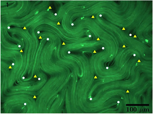
FIGURE 1. Active nematic microtubule system in the “bulk” turbulent state. Microtubule bundles are shown in green, with −1/2 and +1/2 topological defects identified by the triangular and circular symbols respectively. This image is taken from a study of topological chaos in active nematics [6], and is courtesy of Amanda Tan and the Hirst lab at UC Merced.
The local extensile dynamics give rise to a global flow of material points and an interesting time evolution of the nematic field. The topological defects are mobile (particularly the +1/2 defects), and their relative motion about one-another form braids. We can consider the braids formed in this manner to be an emergent feature of the system, and the main theme of this paper concerns which braids are formed.
This can be framed as developing a model of the ANMT system. We can consider a hierarchy of approaches to modeling this system, going from maximalist to minimalist. On the more complex side are agent-based approaches [27], which model the bundles as rods and try to capture the local physics of their interactions. Somewhat simpler are continuum field-based approaches, which describe the state of the system using the director field (or nematic order tensor field) and velocity field, and the dynamics using nematic hydrodynamic equations (PDEs, e.g. Beris-Edwards [9]). Defect dynamics models, which use ODEs to evolve forward the locations and orientations of topological defects, constitute a further reduction in model complexity. This simplification acknowledges that the effective degrees of freedom in an ANMT system are discrete, quite small, and are associated with the defects.
At each reduction step we might loose the ability to capture salient features of the physical system. For example, defect dynamics models inherently neglect creation and annihilation events. Every attempt at modeling a physical system is a trade-off between capturing the full range of physical phenomena and creating a minimal model with as few degrees of freedom as possible. Some systems, ones that physicists love, do well on both counts and are amenable to simple minimal models that are highly expressive. ANMT systems appear to be of this type.
All dynamical models need a description of the system state, a notion of time, and a dynamics principle for advancing the state forward in time. For our minimal model of ANMT dynamics, the system state is discrete with a finite number of configurations. More specifically, a discrete state corresponds to the assignment of labeled defects to the vertices of a particular graph (introduced in Section 3). Time is also discrete; we use algebraic braid generators to record the braiding motion. These generators encode not just the fact of a change from one state to another, but also how that change took place. The dynamics principle is more subtle, and here we think of it as a principle which helps us determine which algebraic braids are actually realized by the ANMT system out of the huge number of logically possible braids.
ANMT systems exhibit a wide variety of behavior, from the bulk “turbulent” state with constant creation and annihilation events to simpler periodic behavior for certain constrained geometries. This minimal model is most powerful when applied to the regime in which periodic behavior occurs. We will consider the effectiveness of our model by analyzing two different ANMT domain geometries: a singly periodic channel (topologically an annular domain) in Section 7, and the sphere in Section 8. Along the way, we will develop two different dynamics principles for the minimal model.
3 Braiding
As we have mentioned, densely packed microtubule bundles confined to a 2D domain are modeled, without much loss of information, by the locations and orientations of defects in the director field. Likewise, the trajectories of these topological defects efficiently encode the overall dynamics of this system. Here, we extend this dimension-reduction idea to a logical extreme by representing the defect trajectories as braids and extracting the associated discrete topological information.
In the traditional braid construction, our trajectories constitute strands in (2 + 1) D space-time, and wind about one-another to form a geometric braid. To obtain an algebraic braid, we choose a plane parallel to the time axis, project the strands onto this plane, and record the time-ordered set of strand crossings with crossing orientation identified. Here, we take a different approach [28]; one that is better suited to describing braids on more general surfaces (e.g. the sphere).
We start with a graph that is embeddable on our surface, where vertices represent defects and edges represent pairs of defects that can swap positions. Each edge is labeled such that the braid generator, σi, represents a counter clockwise swap (and
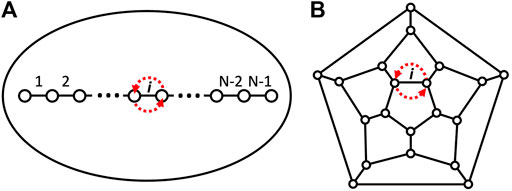
FIGURE 2. Two examples of graphs. (A)—a linear graph on the disk. Point movement consistent with the Artin braid generator σi is shown in red. (B)—the dodecahedral graph on the sphere. Though shown as a planar graph, this can be embedded on the sphere (considering the rest of the plane as a pentagonal face through one point compactification). The braid generator σi is again shown in red.
For example, we can recover the traditional braid construction by choosing a linear graph (points on a line with edges connecting them to their adjacent neighbors, see the left side of Figure 2) on a disk. The projection of our defect locations onto this line defines an ordering of the defects, which, along with the natural ordering of the graph vertices on the line, defines a 1-1 mapping of defects to graph vertices. When the defects move, and the ordering changes, we record the change with the appropriate braid generator. In this example, the braid generators, σi, are the traditional Artin generators of the Artin algebraic representation of braid groups [29–31].
There are two main difficulties in realizing this procedure on arbitrary surfaces: choosing a fixed reference graph, and realizing a procedure for mapping defect positions to vertices on the graph. In general, there might not be a natural choice of graph or mapping. However, this will not be the case for the scenarios we consider in this study. We will detail this braiding construction for defects on an annular domain in Section 7 and for 4 +1/2 defects on a sphere in Section 9.
4 Braiding and Dynamics
Given that many different geometric trajectories can correspond to the same topological braid, what general information is encoded in a braid word, and what does it tell us about the dynamics of the system in which the braid is embedded? The starting place for connecting braids to dynamics is the Nielsen-Thurston classification theorem [32–35] of mapping classes. Out of necessity, we will only convey the basic picture of this beautiful bit of mathematics.
Here, maps are homeomorphisms of the relevant surface to itself, such that the positions of a set of distinguished points remain set-wise unchanged (though possibly permuted). In our case, the Lagrangian map of all material points in an ANMT system that has periodic defect motion is just such a map. Each map is associated with the braid formed from the motion of the distinguished points, and the set of maps associated with a single braid is a mapping class. The Nielsen-Thurston classification theorem says that for each mapping class, there exists a representative map with well defined properties, and that a representative map is one of three types: finite order, pseudo Anosov (pA), or reducible. Finite order braids are simple, and some power of the representative map is the identity. Reducible braids have representative maps that can be cut up into a combination of finite order and pA maps. We will be exclusively interested in pA maps; the connection between pA maps and ANMT systems is discussed in the next section.
Pseudo Anosov maps have very rich behavior despite being simple to characterize. For the representative map, Φ, there exists two measured foliations [34] -
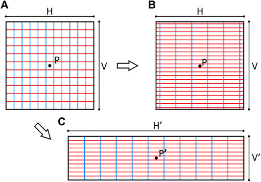
FIGURE 3. The (A) shows two foliations in the neighborhood of a point P,
For the pA map representative, Φ, there exists a positive number, λ, the dilation, such that
The foliations,
Additionally, if the measured foliations are uniform (the transverse measures don’t vary from point to point), then
This braid dilation factor, λ, can be recast as the topological entropy [36–38], h = log(λ). This most salient of braid attributes can be interpreted as the exponential stretching rate of material curves in the surrounding medium upon repeated application of the representative map. Importantly, this ensures that every map in a pA mapping class will have material curves that stretch out with at least this rate, including the map corresponding to the flow of material in our system.
Finally, our foliations are singular foliations, meaning that at discrete points the local foliation structure does not look like the stack of lines in Figure 3, but can have more than one leaf emanating from the singular point. These are called k-prong singularities, for the k half-line leaves attached to the point. The simplest singularities are 1-prong and 3-prong, as seen in Figure 4 (2-prong points are identical to generic points in the foliation, and are therefore not singularities). Figure 4 also shows how
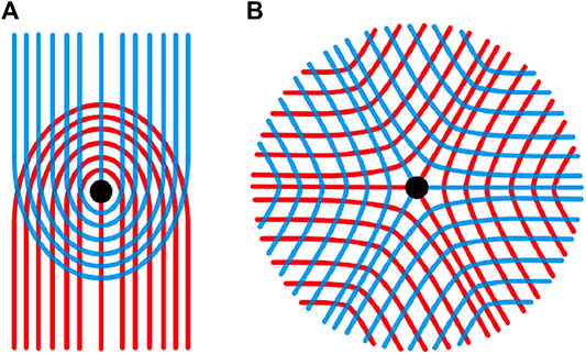
FIGURE 4. Two transverse foliations,
5 Weak Dynamics Principle
In Section 4 we connected braids with dynamics by associating every pA braid with a representative map, Φ, that has stable and unstable singular transverse measured foliations,
There is a natural correspondence between the unstable foliation,
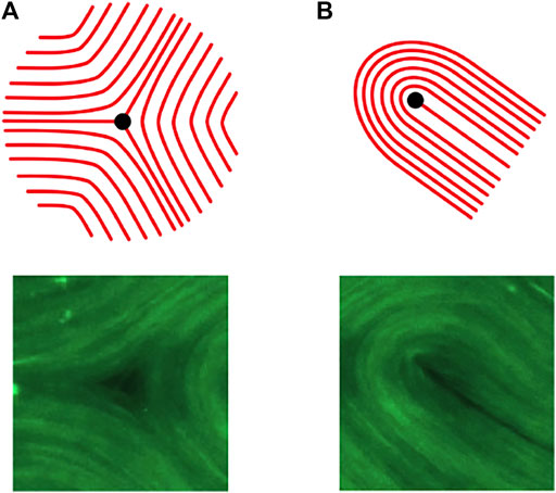
FIGURE 5. (A): The foliation around a 3-prong singularity (Top) and the microtubule bundle configuration about a −1/2 topological defect (Bottom). (B): The foliation around a 1-prong singularity (Top) and the microtubule bundle configuration about a +1/2 topological defect (Bottom). The microtubule images are details from Figure 1.
If we assume a relatively dense packing of microtubules, then there are few if any voids away from defects, and the ANMT bundle is well modeled by foliations with uniform measure (see this paper [39] for an interesting analysis of fractal generation in an ANMT system with density fluctuations). This in-turn suggests that any curve along a leaf will increase in length by a common factor of λ after the mapping. This is exactly what the ANMT system does as a result of extensile dynamics. There is ample evidence [6] that on scales longer than that of the microtubule length, material curves tangent to the bundles extend their length exponentially in time. This extension rate is controlled by the ATP concentration and, due to diffusion and efficient mixing, is very uniform across the domain. This uniform expansion factor (over the time it takes to form the braid) corresponds to the braid dilation.
The density assumption also ensures that the ANMT system is pretty close to area preserving. As the stretching along the unstable direction thins the bundles, more bundles move in transversely to maintain a roughly constant microtubule density. This area conservation means that the compression of material points perpendicular to the bundle orientation contract by a factor of 1/λ. Thus we can visualize the stable foliation as being oriented along these contracting directions.
It is important to note that the remarkably close correspondence between the behavior of the microtubule bundles and that of the unstable foliation indicate that the material flow map of the ANMT system is remarkably close to the minimal representative in the appropriate mapping class. In other words, given the braid formed from the defect trajectories, the flow map of the surrounding material is the simplest possible compatible map. Any additional strands created from the motion of passively advected material points would lead to braids with the same topological entropy. Indeed it has been shown [6] that only the +1/2 defects contribute to the topological entropy; the addition of strands corresponding to the −1/2 defects do not change the complexity of the braid in this respect.
In the usual application of braid theory to fluid dynamics, the braid is often globally specified (e.g. as a stirring protocol for a rod-stirring device) and the result is a forced lower bound on the stretching of material lines. The application of braids to ANMT systems inverts the causality: the stretching rate is a priori specified at the small scale (e.g. controlling ATP concentration), and the braiding pattern of defects is what emerges. From the point of view of braids as a minimal model for the ANMT system, braids encapsulate both the state of the system (where defects are) and the dynamics (how the defects move). However what determines which braids, of the infinite number of logically possible braids, are actually dynamically realized? The simplest dynamics principle for discriminating amongst braids, which we will call the weak dynamics principle, merely notes that the exponential stretching of microtubule bundles implies a braid with dilation λ > 1 (i.e. a pA braid).
Weak Dynamics Principle: The braids that emerge from the motion of topological defects in the director field of an ANMT system must have positive, non-zero topological entropy.
This statement is predicated on a few assumptions that we should explicitly state:
1) The microtubule bundles are densely packed. If they are not densely packed (i.e. there are voids), then the dynamics are not necessarily area preserving and the stable foliation might not be well defined. For very rarefied ANMT systems, the unstable foliation might also be ill-defined.
2) Material lines along microtubule bundles stretch exponential in time with a constant rate that is spatially uniform. Microtubule bundles might have exponential stretching rates that are spatially and temporally nonuniform if mechanical stresses are comparable to the active stresses in some locations. This nonuniformity, while not a deal-breaker, would result in a material flow map that is not minimal in its mapping class. Of course, no stretching (say from too small of an ATP concentration) leads to no movement and no braiding.
3) There are no creation or annihilation events. Creation of pairs of +1/2 and −1/2 defects, as well as their annihilation, complicate the interpretation of braids (though an analysis of topological entropy can still be done [6]). It is this assumption that necessarily breaks down when the weak dynamics principle is applied to the case of two +1/2 defects circling about each-other in a disk geometry. Two stranded braids cannot be pseudo Anosov (need three strands), and therefore have zero topological entropy, so this motion is not possible. In experiments [40], this situation is resolved by pair production then annihilation events periodically interrupting the above mentioned circular motion. Creation and annihilation events can be suppressed by choosing particular domain geometries, and choosing low enough ATP concentrations.
4) The defect motion is periodic. This is more of a minor difficulty. Non-periodic trajectories can still be analyzed with braids [14], though it might take long trajectories for the topological entropy to converge to a well defined value. Periodic motion is desirable, as it produces simple braids that can be easily identified in experiments. Periodic defect motion seems to occur at relatively low activity levels for certain boundary geometries. In the case of a periodic channel geometry (Section 7), the region of parameter space in which periodic behavior occurs has been computationally explored [7, 41]. In general, we will see that periodic defect motion is more essential when considering the strong dynamics principle.
Finally, the weak dynamics principle is useful as a benchmark for evaluating models of ANMT systems. A model that violates this principle is likely not capturing enough of the relevant physics. As an example, this paper [8] developed a numerical model of the movement of four +1/2 defects on a sphere. This model worked well in explaining the dependence of the period of the movement on activity level. However, the defect motion it produced (two pairs of rotating defects, permanently separated by the sphere’s equatorial curve) constituted a braid with zero topological entropy. The real motion of these four defects is more interesting, as we will see in Section 11.
6 Normalized Topological Entropy
Before we look at two particularly nice examples of braiding in an ANMT system, we must refine our notion of topological entropy. Topological entropy is a rate (exponential stretching rate), and the central concern here is how to best normalize it (i.e. a rate in what?). The topological entropy of braids introduced in Section 4 is the rate per application of the braid. This is extensive, in that h(βn) = n h(β) for any braid β. We can convert this to an intensive quantity by normalizing by other extensive braid attributes.
One choice is to normalize by the time it takes to produce the trajectories that give rise to the braid. This topological entropy production per unit time is the most natural measure for analyzing mixing in experimental data. However, there are multiple factors that help determine this value: the speed of defects, the distance between defects, and the intrinsic braiding pattern woven by the points. As we increase ATP concentration, defects move faster and their areal density might change. To isolate the effects of the underlying braiding pattern, we can identify a characteristic time (e.g. from a characteristic speed and distance) and measure the topological entropy production rate per characteristic time. This idea was used [6] to analyze the changes to topological entropy in the bulk “turbulent” ANMT state due to increasing ATP concentration. While the topological entropy per unit time increased with concentration, the topological entropy per unit characteristic time did not change, indicating a common braiding pattern underlying the turbulent ANMT state. We will see analogous, though simpler, behavior in the example of Section 10.
We would like a normalization that is intrinsic to the algebraic braid (i.e. doesn’t require reference to the physical system), and is intensive. One method would be to normalize by the number of generators in the braid word to get the topological entropy per generator (TEPG). The TEPG is intensive in “time”, hTEPG(βn) = hTEPG(β), but not in space. If we denote n adjacent copies of the braid β by ⊕nβ, then hTEPG(⊕nβ) = hTEPG(β)/n. The issue here is that braid generators that happen at the same time are being counted separately. A set of braid generators that can be performed simultaneously is called a braid operation. For a given braid generated on a particular surface graph, we can find the minimum number of braid operations that it is comprised of. This number is the topologically mandated number of time-steps needed to execute the braid. Normalizing the topological entropy by the number of braid operations gives the topological entropy per operation (TEPO) [22],
7 ANMT in a Channel
One of the simplest ways to control an ANMT system is to constrain its movement with the geometry and topology of the surface on which the ANMT system resides. We will see that some of the simplest surfaces can produce simple periodic defect motion. Our first example consists of a rectangular channel with periodic boundary conditions (a topological annulus). This configuration has been studied computationally [7] and experimentally [42]. The computational work found that certain parameter ranges of channel aspect ratio and activity level allowed for periodic motion of the +1/2 defects. This occurred for activity numbers (the ratio of channel width to active length scale) roughly between 17 and 277. The −1/2 defects migrated to the fixed boundaries and were pinned there, while the +1/2 defects aggregated on the channel mid-line. Half of these defects move left, and half right, all while alternating going over and then under the other group. This movement brings to mind the maypole dance of mayday celebrations in Germany. Indeed, the authors of the computational study [7] named this movement after the traditional Scottish Ceilidh dance.
Whatever dance analogy we use, this braid is well known in the braiding literature [22], and is best described using braid generators. First, assume that there are an even number, N, of +1/2 defects. We specify an annular graph which has these defects as vertices, see Figure 6. Thus there are N generators (and their inverses), indexed by the edges in the graph. Note that edge N connects both sides through the periodic boundary. There are many potential braid operations, but we specify just two:
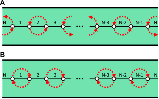
FIGURE 6. Annular braid operations. (A): the braid generators (red arrows) comprising the operation
It has a topological entropy per operation of
8 ANMT on a Sphere
Perhaps the simplest possible geometric domain on which the ANMT dynamics can play out is a sphere. Due to the Gauss-Bonnet theorem, the total topological charge for a surface is equal to its Euler characteristic, χ. For a flat surface or torus, χ = 0, and so the positive and negative defects must balance out. This also explains why defects are produced and annihiliated in pairs of opposite topological charge (total charge is conserved). For the sphere, χ = 2, which is most simply achieved with 4 +1/2 defects. Indeed, this lowest energy configuration persists for non-zero values of the activity, and constitutes the dynamic state in which we will find interesting braiding. The dynamics of 4 +1/2 defects on a sphere have many desirable attributes: there are no negative defects and therefore no annihilation events, the geometry is simple enough to have an explicit method for mapping defect positions to graph vertices, and there are both experimental [8] and numerical [10] studies of this system.
In the pioneering experimental study [8], the defect positions were tracked over time (look for their videos too) and this data was recorded as the pair-wise angular differences between each defect pair (between the two associated radial lines). The time dependence of these angular differences are periodic, as the defects go from a tetrahedral configuration to co-planar and back to tetrahedral. They noted that the period of this motion depended on the activity (and sphere radius), and came up with a simple model of the defect motion to account for this feature. While the model captured the periodicity of the oscillations and their dependence on activity, it did not produce motion consistent with the experimental findings. Indeed, the defect motion due to the model produces a braid that is finite order, and therefore not compatible with the exponential stretching of MT bundles (weak dynamics principle). This motion consisted of rotations of two pairs of defects such that an equatorial curve separating the two pairs is left invariant. In this way, the weak dynamics principle could have been used to detect that this model was not accurately capturing the experimental behavior (though the authors did not consider defect braiding).
Before we analyze the computational (Section 10) and experimental (Section 11) motion of 4 +1/2 defects on a sphere, we must introduce how to describe braids on a sphere.
9 Braids on a Sphere
The first step in describing braids of four points on the sphere is to construct the generating graph. Fortunately, the appropriate graph in this case is unambiguous - the tetrahedral graph. When the four points are in general position (i.e. not in a co-planar configuration), the complete graph, with a geometric embedding formed from the defect locations (vertices) and great arcs (edges) connecting pairs of defects, is a tetrahedral graph (see Figure 7A).
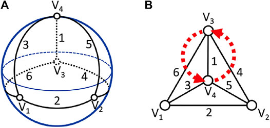
FIGURE 7. Tetrahedral graph of four points on the sphere. (A)—the graph is shown embedded on the sphere, with edges and vertices labeled. (B)—a geometrically simplified version of this graph. Here the fourth tetrahedral face has been expanded to the whole plane (one point compactification gives back the sphere). The pairwise motion associated with braid generator σ1 is shown in red.
This graph encodes two aspects of the system: the association of labeled defects with labeled vertices, which constitutes a discrete encoding of the state of the system, and the labeled edges, which represent the possible braid generators. Consider the defects to have labels 1–4, and the vertices are labeled V = (V1, V2, V3, V4). Now, the state of the system is given by an ordering of the set (1, 2, 3, 4), e.g. V = (1, 4, 2, 3). Of course, there is some ambiguity to this assignment. Permutations of the vertex indexing consistent with the rotational symmetries of the sphere are all equally valid encodings. For instance, V = (1, 2, 3, 4) is consistent with V = (3, 1, 2, 4) after a rotation about an axis connecting the origin and vertex V4, see Figure 7 for the geometry. Indeed, vertex indexing sets are equivalent, due to the rotational symmetries of the sphere, if they are related by an even permutation. This defines two equivalence classes for vertex indexing sets, C1 and C2. C1 consists of all even permutations of (1, 2, 3, 4), while C2 consists of all odd permutations. We will treat the initial choice of vertex indexing set within one of the equivalence classes as a convention (say (1, 2, 3, 4) for C1 and (2, 1, 3, 4) for C2), which, along with the dynamics, removes any ambiguity in the discrete state of the system. You can determine which of C1 or C2 the initial defect positions are consistent with. Right handed tetrahedra have the fourth defect situated above the plane formed from the first three defects (normal to the plane given by right handed ordering of these three points), while left handed tetrahedra have the fourth defect below this plane. Right handed tetrahedra have vertex indexing sets in C1, while left handed tetrahedra correspond to C2. Note that this whole procedure for determining the discrete state of the system is analogous to finding the linear order of defect positions for Artin braids.
Now that we can define a discrete system state, we move on to the second use for our graph - defining braid generators. For simplicity, we will consider the equivalent tetrahedral graph shown on the right of Figure 7. We have six edges, and therefore six braid generators, σi (and inverses,
The rotational symmetries of the sphere were important in making sense of the discrete system state. They are likewise central to finding the minimal set of generators necessary to describe motion. Pairs of generators are equivalent to each other [σ2j ∼ σ2j−1 for j ∈ (1, 2, 3)] if we allow for a rotation after one of the generators. Since there is no dynamical difference between σ1 and σ2, we must choose one and stick with it as a convention. We choose σ1, σ3, σ5. It should be noted that the discrete system state will be different after a σ1, as compared to that after a σ2. However, the choice between the two again constitutes an arbitrary, though necessary convention. Finally, a less obvious relation exists between adjacent edges:
Only one braid generator can be executed at the same time, so the set of braid generators is also the set of braid operations. We would like to find the braid with the largest topological entropy per operation. As a first step, we need a method for finding the TEPO of a given braid word. We outline the method developed in this paper [28], and give the details in Supplementary Appendix S14A. As a reminder, the topological entropy measures the exponential stretching rate of material curves under the action of the braid. We create a coordinate system (intersection coordinates) for discretely encoding closed curves (homotopy classes of these curves). The action of a braid generator on this coordinate system is specified, as are all other generators through symmetry. The sum of the coordinates is a good proxy for the length of the curve, and the asymptotic exponential increase in this value after repeating the braid action constitutes the topological entropy (again, for details see Supplementary Appendix S14A).
We checked braid words up to length 10, and the unique (up to cyclic shifts) braid to maximize TEPO is
This braid has a TEPO of
10 Spherical Example—Computational
A recent paper [10] introduced a computational model for the trajectories of 4 +1/2 defects on the surface of a sphere. The model consists of a set of implicit ordinary differential equations for the evolution of 8 angular variables (spherical coordinate angles for each defect) and one extra variable (which sets the defect orientations). The main free parameter corresponds to the activity level, and increasing it results in faster defect movement. We have implemented this model, using the same initial conditions and computational choices as in the original paper [10], to get the pair-wise angle differences seen in Figure 8. Due to the symmetries of the problem, there are only three unique angle differences, which oscillate periodically.
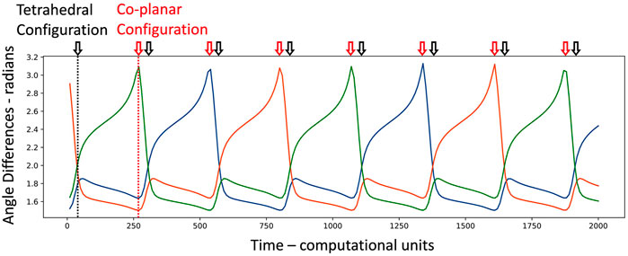
FIGURE 8. Dynamics of 4 +1/2 defects on a sphere. The three independent pair-wise angle differences are shown (green, blue, and orange traces) over time. The motion is periodic, and we can identify the switching of topological configuration from tetrahedral to co-planar, and back to tetrahedral. For comparison with Figures 9, 10, this motion corresponds to an activity level of 0.265 (third data point).
When the defects are close to a tetrahedral configuration, all angles are roughly the same (1.91 radians or 109.5°); when they are co-planar, the smaller angles are π/2 = 1.57 radians and the larger angle is π. The angles in Figure 8 reveal the periodic change in topological configuration—tetrahedral to co-planar and back to tetrahedral. Each time we pass through a co-planar configuration it corresponds to a new braid generator. We can figure out which braid generator if we know the state of the system before the co-planar configuration and know which pairs of defects are along the diagonals of the co-planar configuration, see Supplementary Appendix S14B for the details. The braid corresponding to the trace in Figure 8 is σ1σ1σ5σ5σ3σ3σ1, which, when repeated in the obvious way, is the same as the golden braid of Eq. 3.
Next, we vary the activity level over an appropriate range and see what braiding behavior results. As seen in Figure 9, the topological entropy per unit time (note, not TEPO) monotonically rises with activity level. For activity levels below
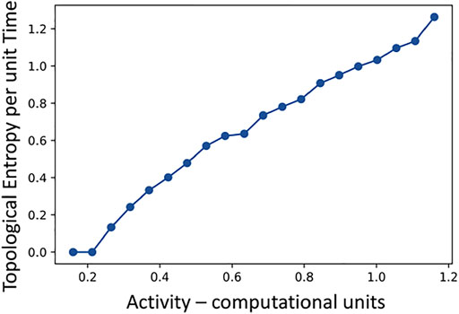
FIGURE 9. The braiding topological entropy per unit time extracted from the movement of 4 +1/2 defects on the sphere for a range of activity levels.
The TEPO over this same activity range behaves quite different, as seen in Figure 10. Here, as soon as the defects start to move, the TEPO value jumps up to its maximum value of
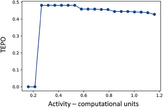
FIGURE 10. The braiding topological entropy per operation (TEPO) extracted from the movement of 4 +1/2 defects on the sphere for a range of activity levels.
Taken together, Figures 9, 10 tell the following story. As soon as the activity level is large enough for the active stresses to overcome the mechanical stresses, the defects start moving in a pattern that produces the braid with maximum possible TEPO, the golden braid. As the activity level increases, the braiding pattern is still the golden braid, but the period of oscillations is shorter. Since the same braiding pattern is executed in a shorter time, the topological entropy per unit time rises. As the activity level rises further, we eventually loose the perfectly periodic defect motion, and the trajectories start to become chaotic. The topological entropy per unit time continues to rise as the defect movements speed up, but the TEPO decreases and is no longer maximal. A typical segment of a braid word from this regime (activity—0.792) is: σ1σ5σ5σ5σ3σ3σ1σ5σ5σ3σ3σ1σ1σ5σ5σ3σ1σ1σ1σ5σ5σ3. Note how this has a similar pattern to the golden braid, just with the occasional deletion or addition of a braid generator. In this way, the max TEPO braid not only dictates the defect movement at low activity levels, but also plays a key organizing role for the movement at higher activity levels.
The behavior of topological entropy per unit time and TEPO in this example is analogous to the results in the bulk turbulence topological entropy study [6]. In both cases, a closer look at how best to normalize topological entropy reveals the existence of a common braiding pattern over a large range of activity levels.
Finally, a future study should look at the onset of chaos in this system. The period doubling route to chaotic defect trajectories should be reflected in analogous, though discrete, behavior in the braids that are generated. Unfortunately, the current computational model [10] has some shortcomings that preclude this right now. The largest issue is that the defects occasionally work their way into a configuration that asymptotically approaches a fixed state with no movement. This non-physical behavior, and others where this defect slow down is transitory, effect the determination of the topological entropy per unit time. Here, we have roughly accounted for this by finding the average time to go between tetrahedral configurations after removing the time intervals that are more than twice as long as the mode of whole set of time intervals. This average period is then used to get the topological entropy per unit time from the more robust TEPO calculation.
11 Spherical Example—Experimental
Is the max TEPO braid for 4 +1/2 defects on a sphere experimentally realized? We return to the original paper [8], which introduced this ANMT system geometry. While we do not have access to their original data, we can back out the braid word corresponding to the movement captured in one of their figures. We have reproduced a cartoon version of their Kymograph in Figure 11. It shows the six pairwise angle differences between the four defects over time, where the angles have been thresholded to clarify the salient information content. At times where two angles are close to 180° and the other four are closer to 90°, the defect configuration is close to co-planar. In between these co-planar times we have tetrahedral configurations. Thus, at each transition from tetrahedral to other tetrahedral configuration, we can determine which pairs of points are diagonal to one-another on the quadrilateral formed while the points are co-planar. This information, along with knowledge of the handedness of the initial tetrahedron, is sufficient to generate the corresponding braid word, see Supplementary Appendix S14B for details.

FIGURE 11. This is a cartoon version of the Kymograph figure (encoding movement as time traces) from the spherical ANMT experimental study [8]. The movement of 4 defects are given by the 6 pairwise angle differences over time. Here we have thresholded the data (closer to 180° or 90°) to highlight the tetrahedron to co-planar to tetrahedron topological changes.
The braid word recovered by this method is
where the braid has been broken up into four chunks to make comparisons easier. The TEPO value is
12 Strong Dynamics Principle
In both of the previous two examples (ANMT system confined to a periodic channel or to the surface of a sphere), the dynamics give rise to emergent braids that not only satisfy the weak dynamics principle, but also seem to maximize the TEPO. This suggests the possibility of a stronger dynamics principle dictating the evolution of our minimal ANMT model.
Strong Dynamics Principle: The braids that emerge from the motion of topological defects in the director field of an ANMT system maximize the topological entropy per operation (TEPO).
Again, we have the same assumptions as with the weak dynamics principle: 1) The microtubule bundles are densely packed, 2) Material lines along microtubule bundles stretch exponential in time with a constant rate that is spatially uniform, 3) There are no creation or annihilation events, and 4) The defect motion is periodic. For the strong dynamics principle, the periodic motion assumption is particularly important (unlike for the weak dynamics principle). As we have seen, deviations from periodic motion (say at higher activity levels for the numerical implementation of four +1/2 defects on a sphere) accompany braids that have TEPO values smaller than the maximum possible.
At this point, we have two examples of defect behavior that satisfy the strong dynamics principle. It is natural to wonder how broadly this principle can be applied, as it all but completely determines the topological dynamics. As we have seen in Section 10, an increase in the activity level will eventually lead to braids with TEPO less than the max TEPO, though this defect motion is chaotic and not periodic. From this, we can see that the max TEPO braid is most likely to be realized for low activity levels (that are high enough for motion to occur).
As a component of our minimal model of simple ANMT behavior, the strong dynamics principle completely determines the topological motion of defects. The resulting unique predicted braid does not change with activity level or other system parameters, and is only seen in the region of parameter space where the motion is periodic. Within this window of periodic motion, the geometric motion of the defects changes with parameter changes (e.g. speeds up with increasing activity, see Figure 9), but the underlying braid remains the same (e.g. see Figure 10). The size and prevalence of this parameter space window does depend on system parameters, and for complex enough system geometries might not exist at all. However, outside this window, the max TEPO braid still influences the defect motion, as realized braids are symbolically close to the max TEPO braid. Additionally, the weak dynamics principle still applies when the defect motion is not strictly periodic.
We have also analyzed arguably the two simplest geometries possible, but this principle could likely be applied to new geometric constraints: a lattice of boundary pillars, the surface of a torus, or the surface of an ellipsoid. For the case of a lattice of pillars or the surface of a torus, the max TEPO braids, and therefore the predicted defect motion via the strong dynamics principle, have already been calculated [28]. Another paper [43] has considered the ellipsoidal geometry case. We believe that the braiding dynamics could be determined by the strong dynamics principle. Here, the max TEPO braid would need to be calculated with braid operations having different weights (corresponding to the differing times it takes to execute the motions).
Finally, there should be a physically explicable reason why max TEPO braids are favored over other braids. Unfortunately, we do not have a complete understanding of this phenomena at this time. If we compare many different braiding patterns, all of which are describing defect motion for an ANMT system at a given activity level (and therefore common stretching rate), then the max TEPO braid will be the one that can be executed with the smallest possible defect speeds. Defects typically move at the same speed as the underlying material, but, not being material points themselves, can move faster (especially when the MT bundles fracture). Thus, a physical reason for slower defect speeds being favored could help better justify the strong dynamics principle.
The realization of max TEPO braids over all the other a-priori possible braids is a global constraint on the dynamics. It would be useful to recast the strong dynamics principle as a local rule for determining the next generator in a braid word, given the current state of the system.
13 Conclusion
It is rather remarkable that a messy experimental system, composed of large numbers of biologically derived microtubules and molecular motors, and fueled by ATP, can be accurately modeled by simple braids with unique properties. From a broader view, we can view all 2D fluids in light of their kinematic mixing properties: How does the stretching and folding of material curves, characteristic of mixing, arise from the coordinated dance of the relative motions of material points? On the complex side there is 2D turbulence, in which a full accounting of mixing requires that we include more and more trajectories to access motion at all scales in the inertial range. The ANMT systems that we have analyzed here lie on the opposite side of this complexity spectrum. While they still produce exponential stretching of material lines, and therefore exhibit Lagrangian chaos of material points, all of the information content is encoded in the topological motion of just a small number of points (the +1/2 defects). In this sense, the ANMT system is as simple as possible while still producing non-trivial mixing behavior. This feature alone should make ANMT systems a canonical example in the fluid dynamics and mixing literature.
In this paper we have argued that much of the behavior of ANMT systems can be generated by a particularly simple minimal model. Here, the state of the system is discretely encoded in the matching of labeled defects with vertices in a graph. The dynamics are recorded in a sequence of braid generators. Instead of equations of motion, we have dynamics principles, which filter out the dynamically permissible braids. The weak dynamics principle says that only braids with non-zero topological entropy are possible, while the strong dynamics principle goes farther and posits that the movement of topological defects weaves braids that maximize topological entropy per operation. We have compiled evidence for these two dynamics principles by considering two simple ANMT system geometries: a periodic channel, and a sphere. Particularly for 4 +1/2 defects on a sphere, the computational and experimental evidence points to the central role of max TEPO braids in ordering the dynamical behavior.
This topological point of view naturally raises as many questions as it answers. In future work, we will be looking for other simple ANMT system geometries to test the strong dynamics principle. We have max TEPO predictions for braids on a torus, which can be realized as braids on a square lattice. ANMT experiments on a square lattice are currently underway. Another direction for future work is to adapt this approach to include creation and annihilation events. This is a challenge for topological braids, however, many of the related topological tools, like train tracks and foliations, can likely provide the starting point. Finally, the dynamics principles are essentially global in their approach. It would be great to have a local approach that can determine which braid generator is next, based on the current state of the system. We believe that topological ideas still have much to say about ANMT systems.
Data Availability Statement
The raw data supporting the conclusion of this article will be made available by the authors, without undue reservation.
Author Contributions
SS did most of the writing and originated the ideas. RG wrote the appendices and helped to write code and analyze results.
Conflict of Interest
The authors declare that the research was conducted in the absence of any commercial or financial relationships that could be construed as a potential conflict of interest.
Publisher’s Note
All claims expressed in this article are solely those of the authors and do not necessarily represent those of their affiliated organizations, or those of the publisher, the editors and the reviewers. Any product that may be evaluated in this article, or claim that may be made by its manufacturer, is not guaranteed or endorsed by the publisher.
Acknowledgments
We are very grateful to Kevin Mitchell for years of discussions on dynamics and for introducing us to the ANMT system as a playground for these mathematical ideas. Many thanks go to Linda Hirst, who helps remind us that real versions of this system are invariably subtler than our models. Finally, a thanks to Jean-Luc Thiffeault, whose ideas on braids and dynamics inspired us to work in this area of applied math.
Supplementary Material
The Supplementary Material for this article can be found online at: https://www.frontiersin.org/articles/10.3389/fphy.2022.880198/full#supplementary-material
References
1. Gompper G, Winkler RG, Speck T, Solon A, Nardini C, Peruani F, et al. The 2020 Motile Active Matter Roadmap. J Phys Condens Matter (2020) 32:193001. doi:10.1088/1361-648x/ab6348
2. Marchetti MC, Joanny JF, Ramaswamy S, Liverpool TB, Prost J, Rao M, et al. Hydrodynamics of Soft Active Matter. Rev Mod Phys (2013) 85:1143–89. doi:10.1103/revmodphys.85.1143
3. Bechinger C, Di Leonardo R, Löwen H, Reichhardt C, Volpe G, Volpe G. Active Particles in Complex and Crowded Environments. Rev Mod Phys (2016) 88:045006. doi:10.1103/revmodphys.88.045006
4. Doostmohammadi A, Ignés-Mullol J, Yeomans JM, Sagués F. Active Nematics. Nat Commun (2018) 9:3246. doi:10.1038/s41467-018-05666-8
5. Sanchez T, Chen DTN, DeCamp SJ, Heymann M, Dogic Z. Spontaneous Motion in Hierarchically Assembled Active Matter. Nature (2012) 491:431–4. doi:10.1038/nature11591
6. Tan AJ, Roberts E, Smith SA, Olvera UA, Arteaga J, Fortini S, et al. Topological Chaos in Active Nematics. Nat Phys (2019) 15:1033–9. doi:10.1038/s41567-019-0600-y
7. Shendruk TN, Doostmohammadi A, Thijssen K, Yeomans JM. Dancing Disclinations in Confined Active Nematics. Soft Matter (2017) 13:3853–62. doi:10.1039/c6sm02310j
8. Keber FC, Loiseau E, Sanchez T, DeCamp SJ, Giomi L, Bowick MJ, et al. Topology and Dynamics of Active Nematic Vesicles. Science (2014) 345:1135–9. doi:10.1126/science.1254784
9. Beris A, Edwards B. Thermodynamics of Flowing Systems: With Internal Microstructure. Oxford, UK: Oxford University Press (1994).
10. Zhang YH, Deserno M, Tu ZC. Dynamics of Active Nematic Defects on the Surface of a Sphere. Phys Rev E (2020) 102:012607. doi:10.1103/PhysRevE.102.012607
11. Boyland PL, Aref H, Stremler MA. Topological Fluid Mechanics of Stirring. J Fluid Mech (2000) 403:277–304. doi:10.1017/s0022112099007107
12. Thiffeault J-L, Finn MD, Gouillart E, Hall T. Topology of Chaotic Mixing Patterns. Chaos (2008) 18:033123. doi:10.1063/1.2973815
13. Thiffeault J-L, Finn MD. Topology, Braids and Mixing in Fluids. Phil Trans R Soc A (2006) 364:3251–66. doi:10.1098/rsta.2006.1899
14. Thiffeault J-L. Braids of Entangled Particle Trajectories. Chaos (2010) 20:017516. doi:10.1063/1.3262494
15. Gouillart E, Thiffeault JL, Finn MD. Topological Mixing with Ghost Rods. Phys Rev E Stat Nonlin Soft Matter Phys (2006) 73:036311. doi:10.1103/PhysRevE.73.036311
16. Allshouse MR, Thiffeault J-L. Detecting Coherent Structures Using Braids. Physica D: Nonlinear Phenomena (2012) 241:95–105. doi:10.1016/j.physd.2011.10.002
17. Filippi M, Budišić M, Allshouse MR, Atis S, Thiffeault J-L, Peacock T. Using Braids to Quantify Interface Growth and Coherence in a Rotor-Oscillator Flow. Phys Rev Fluids (2020) 5:054504. doi:10.1103/physrevfluids.5.054504
18. Boyland P, Stremler M, Aref H. Topological Fluid Mechanics of point Vortex Motions. Physica D: Nonlinear Phenomena (2003) 175:69–95. doi:10.1016/s0167-2789(02)00692-9
19. Smith SA. Point Vortices: Finding Periodic Orbits and Their Topological Classification (2015). arXiv:1510.06756 [nlin.CD].
20. Stremler MA, Chen J. Generating Topological Chaos in Lid-Driven Cavity Flow. Phys Fluids (2007) 19:103602. doi:10.1063/1.2772881
21. Chen J, Stremler MA. Topological Chaos and Mixing in a Three-Dimensional Channel Flow. Phys Fluids (2009) 21:021701. doi:10.1063/1.3076247
22. Finn MD, Thiffeault J-L. Topological Optimization of Rod-Stirring Devices. SIAM Rev (2011) 53:723–43. doi:10.1137/100791828
23. Nayak C, Simon SH, Stern A, Freedman M, Das Sarma S. Non-abelian Anyons and Topological Quantum Computation. Rev Mod Phys (2008) 80:1083–159. doi:10.1103/revmodphys.80.1083
24. Alicea J. New Directions in the Pursuit of Majorana Fermions in Solid State Systems. Rep Prog Phys (2012) 75:076501. doi:10.1088/0034-4885/75/7/076501
25. Wu H-D, Zhou T. Vortex Pinning by the point Potential in Topological Superconductors: A Scheme for Braiding Majorana Bound States. Phys Rev B (2017) 96:184508. doi:10.1103/physrevb.96.184508
26. Ma X, Reichhardt CJO, Reichhardt C. Braiding Majorana Fermions and Creating Quantum Logic gates with Vortices on a Periodic Pinning Structure. Phys Rev B (2020) 101:024514. doi:10.1103/physrevb.101.024514
27. Shaebani MR, Wysocki A, Winkler RG, Gompper G, Rieger H. Computational Models for Active Matter. Nat Rev Phys (2020) 2:181–99. doi:10.1038/s42254-020-0152-1
28. Smith SA, Dunn S. Topological Entropy of Surface Braids and Maximally Efficient Mixing. SIAM J Appl Dynamical Syst (2022) 21.
30. Birman JS. Erratum: “Braids, Links, and Mapping Class Groups” (Ann. Of Math. Studies, No. 82, Princeton Univ. Press, Princeton, N. J., 1974). Toyko: University of Tokyo Press (1975). p. 1. based on lecture notes by James Cannon.
31. Kassel C, Dodane O, Turaev V. Braid Groups, Graduate Texts in Mathematics. New York: Springer (2008).
32. Nielsen J. Surface Transformation Classes of Algebraically Finite Type. Danske Vid Selsk Mat.-Fys Medd (1944) 21:89.
33. Thurston WP. On the Geometry and Dynamics of Diffeomorphisms of Surfaces. Bull Amer Math Soc (1988) 19:417–31. doi:10.1090/s0273-0979-1988-15685-6
34. Fathi A, Laudenbach F, Poénaru V. Thurston’s Work on Surfaces, Mathematical Notes, Vol. 48. Princeton, NJ: Princeton University Press (2012). p. xvi+254. translated from the 1979 French original by Djun M. Kim and Dan Margalit.
35. Casson AJ, Bleiler SA. Automorphisms of Surfaces after Nielsen and Thurston, London Mathematical Society Student Texts, Vol. 9. Cambridge: Cambridge University Press (1988). p. iv+105.
36. Adler RL, Konheim AG, McAndrew MH. Topological Entropy. Trans Amer Math Soc (1965) 114:309–19. doi:10.1090/s0002-9947-1965-0175106-9
37. Bowen R. Entropy for Group Endomorphisms and Homogeneous Spaces. Trans Amer Math Soc (1971) 153:401–14. doi:10.1090/s0002-9947-1971-0274707-x
38. Dinaburg EI. A Correlation between Topological Entropy and Metric Entropy. Dokl Akad Nauk SSSR (1970) 190:19–22.
39. Mitchell KA, Tan AJ, Arteaga J, Hirst LS. Fractal Generation in a Two-Dimensional Active-Nematic Fluid. Chaos (2021) 31:073125. doi:10.1063/5.0050795
40. Opathalage A, Norton MM, Juniper MPN, Langeslay B, Aghvami SA, Fraden S, et al. Self-organized Dynamics and the Transition to Turbulence of Confined Active Nematics. Proc Natl Acad Sci U.S.A (2019) 116:4788–97. doi:10.1073/pnas.1816733116
41. Coelho RCV, Araújo NAM, Telo da Gama MM. Active Nematic-Isotropic Interfaces in Channels. Soft Matter (2019) 15:6819–29. doi:10.1039/c9sm00859d
42. Hardoüin J, Hughes R, Doostmohammadi A, Laurent J, Lopez-Leon T, Yeomans JM, et al. Reconfigurable Flows and Defect Landscape of Confined Active Nematics. Commun Phys (2019) 2:121.
Keywords: active matter, active nematics, braids, dynamical system, topological chaos, topology, topological entropy, mixing
Citation: Smith SA and Gong R (2022) Braiding Dynamics in Active Nematics. Front. Phys. 10:880198. doi: 10.3389/fphy.2022.880198
Received: 21 February 2022; Accepted: 19 May 2022;
Published: 08 June 2022.
Edited by:
Kevin Mitchell, University of California, Merced, United StatesReviewed by:
Charles Reichhardt, Los Alamos National Laboratory (DOE), United StatesRodrigo Coelho, University of Lisbon, Portugal
Copyright © 2022 Smith and Gong. This is an open-access article distributed under the terms of the Creative Commons Attribution License (CC BY). The use, distribution or reproduction in other forums is permitted, provided the original author(s) and the copyright owner(s) are credited and that the original publication in this journal is cited, in accordance with accepted academic practice. No use, distribution or reproduction is permitted which does not comply with these terms.
*Correspondence: Spencer Ambrose Smith, c21pdGhzQG10aG9seW9rZS5lZHU=
 Spencer Ambrose Smith
 Ruozhen Gong