
94% of researchers rate our articles as excellent or good
Learn more about the work of our research integrity team to safeguard the quality of each article we publish.
Find out more
ORIGINAL RESEARCH article
Front. Phys., 05 October 2022
Sec. Chemical Physics and Physical Chemistry
Volume 10 - 2022 | https://doi.org/10.3389/fphy.2022.866577
We describe the thermodynamic state of a single-phase fluid confined to a porous medium with Hill’s thermodynamics of small systems, also known as nanothermodynamics. This way of defining small system thermodynamics, with a separate set of control variables, may be useful for the study of transport in non-deformable porous media, where presently no consensus exists on pressure computations. For a confined fluid, we observe that there are two pressures, the integral and the differential pressures. We use molecular simulations to investigate and confirm the nanothermodynamic relations for a representative elementary volume (REV). For a model system of a single-phase fluid in a face-centered cubic lattice of solid spheres of varying porosity, we calculate the fluid density, fluid-solid surface tension, replica energy, integral pressure, entropy, and internal energy.
Transport in porous media takes place in a vast range of systems, natural as well as man-made. It is thus important to have a deep understanding of the relevant driving forces and their coupling, for instance to describe production of clean water [1–3], CO2 sequestration [4–6], transport of oxygen, hydrogen, and water in fuel cell catalytic layers [7, 8], and transport in lithium-ion battery electrodes and separators [9–11].
The long-range aim of this work is to obtain a general thermodynamic theory of transport of immiscible fluids in porous media on the macroscale [12–14]. In this work, we pursue a thermodynamic route to define the pressures of fluids in porous media, as opposed to a mechanical definition. The aim is to provide a thermodynamic basis for Darcy’s law. This theory must first describe the thermodynamic state of the fluids in the porous media. To do this we use a bottom-up approach, a procedure that includes all details of the system on the nanoscale in the construction of a representative elementary volume (REV) [15–17]. The procedure gives a coarse-grained description of the REV on the macroscale, or what is called the Darcy level [12–16]. A central issue is to find the pressure of the REV. Figure 1 illustrates the problem for the cases studied in this work. A fluid (blue) occupies the pores in a porous material (grey). The pores are so narrow that interactions between fluid and wall become significant, or in other words, that the fluid-wall surface energy becomes significant. But how can we define and determine the properties of the REV, for instance, the pressure? Can we find a representative elementary volume, for which this is possible? In this work, we aim to find answers to these questions.
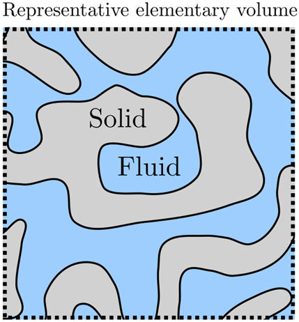
FIGURE 1. A single-phase and -component fluid in a porous medium. The fluid-solid interfaces can have complex shapes and the volumes can be on the nanoscale.
In bulk fluids, the hydrostatic pressure is well defined, measurable, and well documented as the driving force of the fluid flow. In porous media, where fluids are confined by the pores, however, there is no consensus of neither the thermodynamic nor the mechanical definitions of the pressures. It requires special treatment due to the heterogeneity of the system. In this work, we use nanothermodynamics to define thermodynamic pressures of fluids in porous media. The microscopic mechanical pressure tensor is inherently ambiguous [18, 19]. In this context, we make an emphasis on the milestone work of Israelachvili [20] who documented short- and long-range forces on fluid particles exerted by the surroundings, and on the thermodynamic analysis that was pioneered by Derjaguin [21].
We have previously proposed thermodynamic definitions for the pressure of heterogeneous media, applying Hill’s idea of thermodynamics for small systems [13, 14, 22–24]. Hill’s definitions have so far only been tested under simple conditions [22, 23, 25, 26]. They have not been studied for a variety of shapes and pore sizes.
In Hill’s thermodynamics of small systems or nanothermodynamics (See Bedeaux, Kjelstrup and Schnell [17]), the REV of the porous medium is considered as an open system, controlled by the temperature, chemical potential, or pressure in the environment. The thermodynamic analysis is thus applied to a grand canonical ensemble of systems and a new variable is introduced, the replica energy, i.e., the energy needed to create one more small system in the ensemble. An adjusted Gibbs-Duhem equation (the Hill-Gibbs-Duhem’s equation) appears. This opens up a new route to determine the REV pressure.
Using this as a starting point in Section 2, we shall find expressions for the so-called integral and differential pressures of the REV, from the system’s replica energy. We present a new route to the pressure via the chemical potential of the reservoir in equilibrium with the REV. Molecular dynamics simulations, described in Section 3, will be used to illustrate and verify the theoretical steps.
The systematic procedure of Hill consists of the three steps [17], which we repeat to give an overview of the procedure. Concepts will be defined in the text that follows.
1. To start, define the items which make the system small in Hill’s sense, by defining the relevant REV. Find the corresponding Hill-Gibbs equation. Next, define the environmental variables that control the system.
2. From an analysis of the ensemble of small systems, find the system’s replica energy in terms of its subdivision potential.
3. Derive the corresponding Hill-Gibbs-Duhem equation. This equation can be used to find the REV thermodynamic variables and their interrelations.
We shall consider the REV of a porous medium, filled with a single-phase, single-component fluid, see Figure 1. The REV volume is V = Vf + Vs, where Vf is the volume of the fluid and Vs is the volume of the solid. The porosity is the fraction of the fluid volume to the total volume, ϕ = Vf/V. These are time-independent properties in the system. The REV is a small system in Hill’s sense [17, 27] because the fluid is confined; it does not have bulk-scale properties. The system is open for the supply of fluid particles and energy. The number of solid particles is fixed, however.
The ensemble of
This equation has been called the Hill-Gibbs equation [17, 23]. The temperature, fluid pressure, and solid pressures, chemical potentials, and surface tension are defined from the variables involved as
The subdivision potential ɛ is the property that deals with system smallness in particular. It is an additional energy which is covering all the energy contributions not described by the other variables and is therefore dependent on the chosen set of control variables [23, 25]. It is introduced with its conjugate variable, the number of REVs,
When the subdivision potential differs from zero the system is small. This property will, as we shall see below, adjust the common variables like the pressure, and turn them into effective new variables. In the case of the pressure, the adjustment leads to the integral pressure, central for porous media.
To find the properties of one system, we need to describe the thermodynamic state of a single-phase, single-component fluid in the REV. The fluid is free to move (the system is open), while the solid is not. The system exchanges fluid particles with the surroundings, but not solid particles. The variables that are controlled by contact with the environment are the temperature and the fluid chemical potential. Apart from these, as stated above, the fluid volume, solid volume, surface area, and the number of solid particles are control variables too. The type of ensemble constituted by this set of variables is particularly suited for the transport of fluids through a porous medium.
In order to change the set of variables in the general expression Eq. 1, into the above preferred set of control variables, we express the additive variables in the original set of total variables by their controlled value times the number of replicas. This provides also the single system properties that we are after. The controlled fluid and solid volumes, and surface area per REV are
where the last term is the replica energy of one small system
The replica energy [27, 28] expresses in a simpler way, the energy required to add one more small system to the ensemble of systems under the conditions controlled. The combination of terms can define the integral pressure minus the integral solid chemical potential times number of solid particles,
however, we need an additional equation to determine both
We are now in a position to integrate the total differential of the total internal energy, see Eq. 4, at constant T, Vf, Vs, μf, Ns, and A. This gives,
By introducing the REV average properties, we obtain the internal energy of one REV,
The total differential of the internal energy of one REV is
By differentiating the internal energy of the REV and using its total differential, we obtain the total differential of the replica energy
The equation is the outcome of step 2 in Hill’s procedure presented in the introduction to this section. The equation can be seen as an extension of Gibbs-Duhem’s equation, so we have called it Hill-Gibbs-Duhem’s equation [17]. Applications can now be specified.
The partial derivatives of the replica energy follow
With this set of equations we can calculate all the necessary REV properties of a porous medium. We shall concentrate on the integral fluid pressure and the route to this quantity via the chemical potential.
We apply here the conditions of constant temperature, fluid volume, solid volume, number of solid particles, and surface area. The Hill-Gibbs-Duhem’s equation reduces to
or, after dividing by V, the volume of the REV,
Where the density of the fluid in the REV is ρf = Nf/V and the density of the solid is ρs = Ns/V. These densities are of the total REV volume V, and not the fluid volume Vf or solid volume Vs. The difference of the replica energy density can be calculated from
The replica energy density is zero as the fluid chemical potential approaches minus infinity. The replica energy density depends on two unknown variables,
The integral pressure of the REV can be obtained from Eq. 13
The fluid in the porous medium is in equilibrium with its environment, here the bulk phase fluid that surrounds the system (denoted b). The environment has the same temperature. The integral pressure was observed to be constant across the phase boundary inside a pore [25]. We shall therefore make the assumption that also in this case;
where pb is the bulk pressure of a fluid in equilibrium with the porous medium. For an ideal gas in a cubic confinement it has been shown that the integral pressure is equal to the bulk pressure [29]. If this applies for this system, we also have
where ρb is the fluid number density in the bulk phase. The integral pressure is zero as the fluid chemical potential approaches minus infinity. As a consequence, the integral pressure depends only on the fluid chemical potential and temperature. The integral chemical potential of the solid in the REV is then
The solid chemical potential is zero at minus infinite fluid chemical potential. The entropy density of the REV is
where we used Eq. 8 and introduced the replica energy density, x.
There are three pressures; the integral, fluid and solid pressures. The integral pressure is a combination of the pressures of the fluid and the solid pressure as well as the surface tension,
We assume the integral pressure to be equal everywhere in equilibrium and also equal to the bulk pressure of a bulk fluid in equilibrium with the porous medium. If we also assume the distances between solid surfaces to be large and their curvature to be small, we can approximate the fluid pressure to be equal to the bulk pressure [23]. In that case, the solid pressure is equal to
Systems of fluid and solid particles were investigated with molecular dynamics simulations using LAMMPS [30, 31]. The three different systems have been simulated: A bulk fluid, a single solid particle surrounded by fluid particles, and a face-centered cubic (fcc) lattice of solid particles filled with fluid particles in the pore space. The two latter systems are illustrated in Figure 2. The systems were simulated in the grand canonical ensemble and had periodic boundary conditions in all directions. The bulk fluid was simulated to calculate the bulk pressure as a function of the fluid chemical potential. The single solid particle surrounded by fluid particles will be considered as if the lattice constant of the fcc lattice is large. This system was simulated to calculate the fluid-solid surface tension when the solid particles are far apart. The thermodynamic properties of the fluid in the fcc lattice were calculated as a function of the fluid chemical potential.
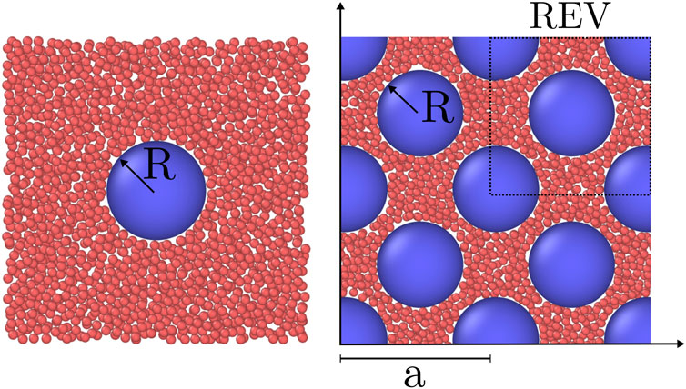
FIGURE 2. Visualization of a two of the simulated systems. Fluid particles (red) and solid particles (blue) are visualised with OVITO [32]. Only the particles in a slab centered on the solid particles of thickness 2.5σ is shown. The fluid chemical potential is μf = ξ and the radius of the solid particle is R = 5σ, where ξ is the minimum of the interaction potential and σ is the soft-core diameter of the fluid particles. Left: Single solid particle. Right: An fcc lattice with lattice constant a = 17.5σ and porosity ϕ = 0.61.
The temperature was controlled to be T = 1ϵ/kB by using a Nosé-Hoover thermostat [33, 34] adapted by Shinoda et al. [35]. The fluid chemical potential was controlled by using grand canonical Monte Carlo insertions and deletions of fluid particles [36]. A particle is inserted at random position in the simulation box with a probability
A random particle is removed from the simulation box with a probability
Where
In the bulk system, the fluid chemical potential was varied in the range μf ∈ [ − 7, 1]ξ, in which the fluid density varied from a dilute gas to a dense liquid. The system was initialized with an empty cubic simulation box of volume V = (40σ)3, and the grand canonical Monte Carlo technique was used to insert particles. The Lennard-Jones parameters ξ and σ are the minimum of the interaction potential and the soft-core diameter of the fluid particles, respectively. The simulation was run until the average number of fluid particles was no longer increasing. The bulk fluid number density ρb = Nf/V and pressure p = (Pxx + Pyy + Pzz)/3 were calculated as a function of the fluid chemical potential for 107 steps. The calculation of the mechanical pressure tensor Pαβ is described below in Section 3.4.
The system of the single solid particle was simulated by first placing the solid particle in the center of the cubic simulation box of volume V = (30σ)3. The radius of the solid particle was R = 5σ, where σ is the diameter of the fluid particle. The fluid chemical potential was varied in the range μ ∈ [ − 7, 1]ζ, where ζ is the minimum of the pair-wise interaction. The system was initialized by placing the fluid particles in an fcc lattice with a fluid number density approximately equal to the bulk fluid number density around the solid particle at a given fluid chemical potential. This was done to reduce the computational time. The simulation was run until the average number of fluid particles no longer increased, after which it was run for an additional 107 steps to calculate the surface tension as a function of the fluid chemical potential. The calculation of the surface is described below in Section 3.4.
The fcc lattice of solid particles was fixed in space with lattice constant in the range a ∈ [15, 30]σ, the radius of the solid particles was R = 5σ. The simulation box lengths were L = 2a, total volume V = 8a3, number of solid particles Ns = 32, and solid volume Vs = 128πR3/3. We have previously found that the smallest REV of such a system is a quarter unit cell [22]. The fluid particles were inserted in the pore space in between the solid particles. The porosity of the system was
where the radius of the solid particles was R = 5σ given that the lattice constant is
The system was initialized by placing the solid particles in an fcc lattice with lattice constant a and fluid particles also in an fcc lattice with a number density approximately equal to ρb(μf) around the solid particles. The simulation was run until the number of fluid particles was constant, after which the simulation was run for an additional 107 timesteps to calculate thermodynamic properties.
The particles interacted with the Lennard-Jones/spline (LJ/s) potential [37], which is equal to the Lennard-Jones potential up to the inflection point rs shifted by a hard-core diameter d. At rs a third degree polynomial is fitted for the potential to be zero at the cut-off rc and the force and potential to be continuous at the inflection point rs and cut-off rc. See the works by Hafskjold et al. [37] and Kristiansen [38] for details on the properties of the LJ/s potential. The LJ/s potential is,
where ζ is the minimum of the interaction potential. This symbol is used to avoid confusion with the subdivision potential ɛ. The soft-core diameter is σ, d is the hard-core diameter, r = |rj − ri| is the distance between particle i and j. The distance r = σ + d is the smallest distance where the potential is zero. The Lennard-Jones/spline interaction potential was equal for all particle pairs, but was shifted with hard-core diameter d. There were three particle pair interactions, fluid-fluid, fluid-solid, and solid-solid, and only the hard-core diameter varied between them. The solid-solid interaction we set to zero. The hard-core diameter was dff = 0, dfs = 4.5σ, and dss = 9σ for the fluid-fluid, fluid-solid, and solid-solid interactions, respectively. The solid particle radius was defined as R ≡ (dss + σ)/2 = 5σ. Other definitions of the radii are possible, for example based on Gibbs dividing surface or the surface of tension. The parameters a, b, rs and rc were determined such that the potential and the force were continuous at r = rs and r = rc. The masses of fluid particles were m, and the solid particles were considered to have infinite mass as they were fixed in space.
The internal energy density was calculated as the sum of the kinetic and potential energy densities,
where V is the total volume, N is the total number of particles, and vi is the velocity of particle i. The solid particles did not contribute to the kinetic energy, as their velocities were controlled to be zero. The internal energy density was used to calculate the entropy density, see Eq. 19.
The mechanical pressure tensor was calculated in spherical and Cartesian coordinates, see Ikeshoji et al. for details [39]. It was calculated in spherical coordinates for the single solid particle surrounded by fluid, and in Cartesian coordinates for the bulk fluid and the fcc lattice of solid particles with inserted fluid particles. For the bulk fluid and fcc lattice, the pressure was calculated for the whole simulation box, with sides L ∈ [30, 60]σ and interaction cut-off rc ≈ 1.74σ. While for the single solid particle it was calculated in spherical shell subvolumes with the origin at the center of the solid particle. This was done to calculate the surface tension.
To avoid confusion between the thermodynamic and mechanical pressures, we will use lower case p for all thermodynamic pressures and upper case P for mechanical pressures. We make this distinction because there is no consensus on how, if possible, to connect the two for heterogeneous media [23, 40–42].
The mechanical pressure tensor can be written as the sum of the ideal gas contribution and a virial contribution,
where δαβ is the Kronecker delta and the subscripts give the components of the tensor. The virial contribution is due to particle pair interaction, and is calculated as a sum over all particle pairs. For a subvolume Vk the virial contribution is
Where N is the total number of particles and fij,α is the α-component of force acting on particle i due to particle j. The line integral is along the part of the curve Cij that is contained in the subvolume Vk. The virial contribution is inherently ambiguous as any continuous curve that starts at the center particle i and ends at the center particle j is permitted [18, 19, 43]. In this work, we have used the Irving-Kirkwood curve, which is the straight line from the center of particle i to the center of particle j.
The Cartesian mechanical pressure tensor was calculated for the whole simulation box. The line integral in the virial contribution reduces it to
where rij is the line for the center of particle i to the center of particle j.
The pressure is calculated as the mean of the diagonal components of the Cartesian mechanical pressure tensor. The bulk pressure is
This was also calculated for the fluid in the fcc lattice of solid spheres. However, we have not equated it to a thermodynamic property.
The fluid-solid surface tension was calculated for the single-sphere simulation case from the spherical mechanical pressure tensor,
Where R = 5σ is the solid particle radius, and r0 = 14σ is a position in the fluid far away from the fluid-solid surface. The normal component is PN = Prr and the tangential component is PT = (Pϕϕ + Pθθ)/2. This is the fluid-solid surface tension of the porous medium given that the surfaces are sufficiently far apart. This will be used to calculate the solid pressure, see Eq. 21.
For the single solid sphere, we show the local fluid number density and mechanical pressure tensor components of the surrounding fluids in Figure 3. The fluid chemical potential is fixed at the minimum of the pair-wise interaction potential, ζ, giving μf = 1ζ. At this fluid chemical potential, the bulk density is ρb = 0.8σ−3. The fluid particles pack in layers close to the surface of the solid particle of radius R = 5σ, as reflected in the density variations in Figure 3. The tangential component of the mechanical pressure tensor, shown in orange to the right in the figure, has the same variation. The normal and tangential components were used to calculate the surface tension, shown in Figure 4 (see below). In this calculation, we do not equate the solid pressure to the mechanical pressure in any way. Inside the solid particle, the tangential component is zero. This is because the cut-off of the fluid-fluid interaction is relatively short, meaning that no fluid-fluid interaction contributes to the pressure inside the solid sphere. It is only the fluid-solid interactions that contribute to the pressure inside, and these contribute only to the normal component. The normal component is proportional to r−2 as a consequence, see Figure 3. This follows from mechanical equilibrium in spherical coordinates,
We used mechanical equilibrium and found that the mechanical pressure calculation in spherical coordinates is consistent with this.

FIGURE 3. Local fluid number density (left) and normal and tangential pressure tensor components (right) in spherical shells as a function of the distance from the center of the spherical particle in the single-sphere simulation case. The fluid chemical potential is fixed to μf = 1ζ and the particle radius is R = 5σ.
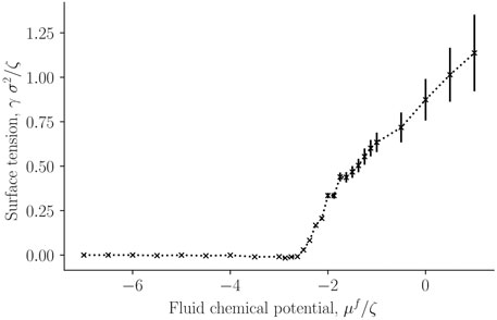
FIGURE 4. Surface tension for the single-sphere case γ as a function of fluid chemical potential μf.
The surface tension was calculated for a single solid sphere surrounded by fluid particles, as a function of the fluid chemical potential. This is presented in Figure 4. It was calculated from the components of the mechanical pressure tensor, see Eq. 31. Fluid particles have reduced contact with each other and with the solid in the lower chemical potential-regime (μf ∈ [ − 7, − 3]ζ), which is characterized by low densities. The surface tension is accordingly very small. The surface tension between fluid and solid increases sharply at a chemical potential of around μf = −2.3ζ. The increase indicates increasing interactions between particles (fluid-fluid and fluid-solid). For a chemical potential below ≈ 2.3ζ, the fluid is more vapor-like, while above this value, it is more liquid-like.
In figure 5 the corresponding solid pressure is shown as a function of fluid chemical potential for a single-sphere surrounded by fluid particles. It is calculated from the surface tension and bulk pressure, see Eq. 21. The bulk pressure monotonically increases with the fluid chemical potential.
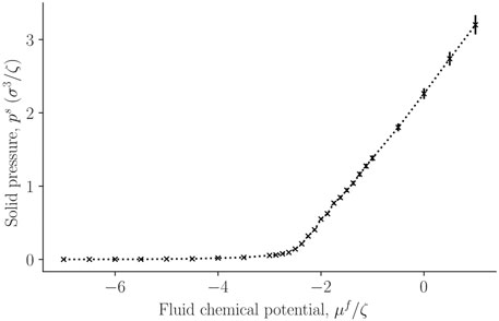
FIGURE 5. The solid pressure, ps, in a single sphere, calculated from Eq. 21 as a function of the fluid chemical potential μf of the surrounding fluid.
So far, the variations are all expected from mechanical equilibrium and standard thermodynamics as given by the Young-Laplace equation. It is reasonable that the pressure of the solid increases monotonously, following the variation in the surface tension.
Figure 6 presents the fluid number density ρf = Nf/V, where V is the total REV volume, as a function of the controlled fluid chemical potential μf for various porosities ϕ of the fcc lattice. Results shown as black crosses represent bulk fluid or the limit where the porosity approaches unity. The fluid number density starts at approximately zero density for small fluid chemical potentials (a dilute gas-like phase) and converges to a density of a dense liquid-like phase. The fluid number density decreases with decreasing porosity, which is mainly because of decreased fluid volume compared to total volume. The fluid particles form layers on the solid surface, as was seen in Figure 3.
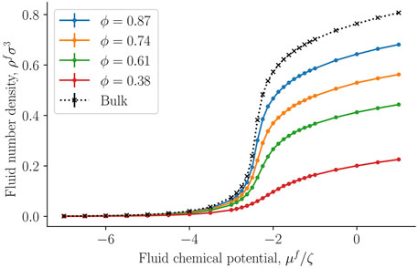
FIGURE 6. Fluid number density ρf = Nf/V as a function of fluid chemical potential μf at varying porosity ϕ = Vf/V.
The replica energy density is a characteristic property of the small system. It is shown for the first time for a regular fcc-lattice in Figure 7. The property was obtained as the integral over the fluid density, of the fluid chemical potential, see Eq. 14. The replica energy density approaches the bulk fluid value (black crosses) in the thermodynamic limit of increasing porosity, as expected. We see a similar development in the replica energy density, as seen in the curve for the pressure of the solid around the single sphere. The replica energy is negative and increases with decreasing porosity. When compared with other thermodynamic properties like the internal energy (see below), the value is sizable.
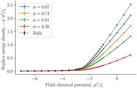
FIGURE 7. The negative replica energy density − x = −X/V as a function of the fluid chemical potential μf at varying porosities ϕ = Vf/V.
The integral solid chemical potential was next calculated from the fluid number density of the REV and the bulk, see Eq. 18. It is presented in Figure 8 as a function of the fluid chemical potential. The integral solid chemical potential is much larger than the fluid chemical potential because each solid particle has a radius ten times larger than a fluid particle. This implies that each solid particle interacts with more particles than each fluid particle. The energy required to add one more solid particle is very large compared to adding one more fluid particle. Interestingly, the integral solid chemical potential is independent of the porosity, it is a function of fluid number density and fluid chemical potential. We interpret this to mean that the solid particle are sufficiently far away from each other, such that the integral solid chemical potential is unaffected by the porosity.
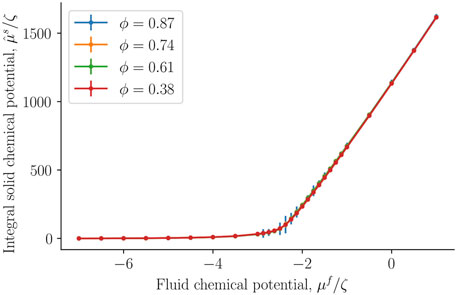
FIGURE 8. Integral solid chemical potential as a function of the fluid chemical potential μf at varying porosities ϕ = Vf/V.
Figure 9 compares the average of the diagonal components of the mechanical pressure for the bulk fluid (black crosses) and the fcc lattice of spheres filled with fluid particles. The mechanical pressure was calculated in Cartesian coordinates for the whole simulation box, as described by Eq. 29. The bulk value was now equated to the thermodynamic bulk pressure, which was assumed to be equal to the integral pressure. Note that we did not equate the trace of the mechanical pressure tensor in the heterogeneous porous medium to any thermodynamic property. Figure 9 serves purely for a comparison. However, even though the geometry inside the porous medium is more complex than what can be captured by the Cartesian mechanical pressure tensor, the values fall almost on the same line. This could suggest that the mean of the diagonal components of the Cartesian mechanical pressure tensor gives the integral pressure. An exception is seen for the data obtained with the smallest porosity, ϕ = 0.38, when fluid chemical potentials vary between approximately μ = −2ζ and μ = −ζ. The given porosity is near the closest packing possible for spheres. While this is interesting, it may only hold for the present case, with a relatively simple structure.
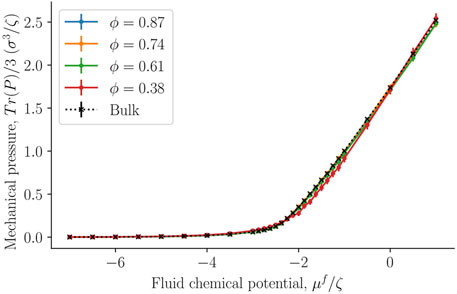
FIGURE 9. Trace of the mechanical pressure divided by three as a function of the fluid chemical potential μf for varying porosities ϕ = Vf/V.
The internal energy and entropy densities as a function of the fluid chemical potential are presented in Figures 10,11, respectively. The internal energy and entropy are divided by the REV volume V to give the respective densities. The variation in the internal energy and entropy densities as a function of the fluid chemical potential, is similar to that shown by fluids above the critical point, when they are described by cubic equations of state, for example, the van der Waals equations of state. It is therefore reasonable that the maxima of the internal energy and entropy densities are a consequence of a structural transition that takes place at the chemical potential in question. This will explain why all maxima are located at the same chemical potential (-2.3 ζ). This location is close to the value of the chemical potential, where the fluid-solid surface tension starts to increase and also where the replica energy density begins to deviate stronger from its bulk value (see Figures 4, 7). The maxima locations remain at the same chemical potential, as the porosity decreases and are given by the location in the bulk fluid. It may therefore be possible to estimate this position using the equation of state for the bulk fluid. Thus, one can determine for which fluid states it is particularly important to take the system size into account.
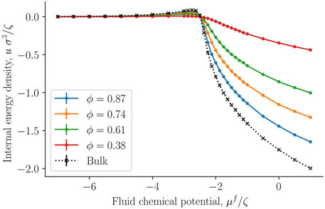
FIGURE 10. Internal energy density u = U/V as a function of the fluid chemical potential μf for varying porosities ϕ = Vf/V.
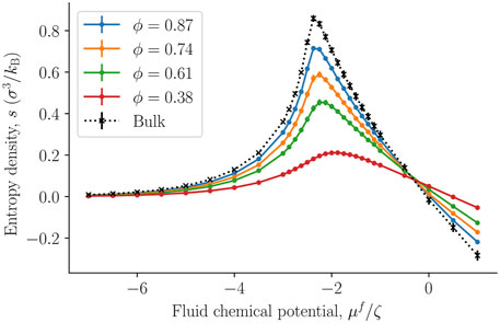
FIGURE 11. The entropy density s = S/V as a function of the fluid chemical potential μf for varying porosities ϕ = Vf/V. The integral pressure is assumed to be equal to the bulk pressure.
The absolute value of the internal energy density decreased with the porosity, reflecting the fact that the fluid number density decreased with the porosity. The entropy density became larger as we approached the bulk value. This observation is typical for phase transitions in small systems, it becomes less clear cut first order, and has less of a discontinuity in the phase variables [28].
A system is small in the sense of Hill when we need to take into account the subdivision potential to accurately describe the system [17]. We have shown in earlier work, that the value of the subdivision potential depends on the chosen set of control variables [23, 25]. This means, that if the system and all the energy contributions are fully accounted for in the description, the subdivision potential becomes zero. The subdivision potential further depends on the choice of the REV. If the REV, for example, is chosen such that it is macroscopic by definition, then the subdivision potential cannot account for small system effects. This, however, does not mean that there are no local small system contributions present in a macroscopic REV. This is indicated in a general manner in Eq. 1. For a macroscopic REV, it is thus necessary to either determine the dependency of the hat-variables in Eq. 1 on local small system effects, or to choose and determine the respective variables such that they automatically include all the contributions. We have chosen the latter approach for this work.
The smallness of a system can also be measured by the replica energy (for the present system, see Eq. 5). The replica energy depends also on the set of control variables, and has accordingly an equivalent bulk variable [17]. It changes proportional to the subdivision potential as the value of the subdivision potential is in general included in the deviation of the replica energy from the corresponding value of a bulk fluid, see Eq. 5. While a change in replica energy is expected with additional contributions of the solid, the application of the replica energy as a variable allows us to quantify the smallness of the system. However, for evaluation of the state of smallness, the single contributions given in Eq. 5 must be computed independent of one another. This we were not able to do in the present work. The replica energy density may still be used to assess whether small system effects can be neglected or not. This can be done by evaluating the total replica energy difference together with the entropy density. Consider for the purpose of such an evaluation the left-hand side of the peak in entropy density. Due to the small replica energy differences between the fluid bulk value and the corresponding values of the nanoporous medium for small chemical potentials, it may be speculated that small system effects are negligible for vapor-like densities. On the right hand side of the peak, the difference is sizeable which is why the small system effects cannot be assumed to be negligible a priori.
We are now in a position to discuss, if not answer completely, the questions posed upfront; what is the pressure of a representative elementary volume (REV)?
In the present case, the structure of the porous system was regular fcc, and all different microstates are represented by a small REV, a unit cell for all practical purposes. A system with irregular structure has probably a larger REV. All thermodynamic properties defined, refer to the actual REV.
Equations 15, 16, 20 most central in the description. These relations were derived using Hill’s systematic procedure for porous media with nanoscale pores. The effective pressure
In order to proceed, we have next taken the bold assumption stated in Eq. 16, that the integral pressure
The mean of the diagonal components of the Cartesian mechanical pressure tensor, presented in Figure 9, gives a good approximation of the integral pressure for the largest porosities. This can give an alternative route to obtain the integral pressure when the porosity is large. However, for small porosities it deviates from the bulk pressure and the integral pressure.
The thermodynamic method of Hill for nanoscale systems was used to describe the thermodynamic state of a single-phase fluid confined to a porous medium. The size and shape of the porous media were restricted, such that the description can be said to be general for any porous media.
The system was open for fluid to be exchanged with the environment, while the solid was not allowed to be exchanged with the environment. In addition, the temperature was controlled by the environment, and the fluid and solid volumes, surface area, and number of solid particles were controlled.
Nanothermodynamics introduces two new conjugate variables, the subdivision potential and the number of replicas. The subdivision potential was incorporated into the definition of the integral pressure and integral solid chemical potential. A fundamental assumption used in this work is that the integral pressure is constant everywhere in equilibrium. We have shown in previous works that this holds for simple porous media such as the slit pore [23, 25].
We have used this framework to demonstrate how to compute the fluid number density, replica energy density, integral solid chemical potential, internal energy density, and entropy density of a fluid confined to a face-centered cubic lattice of solid particles. The radius of the solid particles was ten times larger than the fluid particles, and the porosity varied from ϕ = 0.38 to ϕ = 0.87. These porosities range from almost closest packing to rather open structures. We have used this system as a relatively simple model of porous media, computing all its thermodynamic properties, in particular its integral pressure, liquid-solid surface tension, and solid pressure of a single solid particle surrounded by fluid particles.
This way of defining the small system thermodynamic properties, for a given set of control variables, may be useful for the study of transport in non-deformable porous media.
The original contributions presented in the study are included in the article/Supplementary Material, further inquiries can be directed to the corresponding author, 10.5281/zenodo.6472323.
OG contributed to formal analysis, investigation, methodology, software, and visualization. DB and SK contributed to supervision. All authors contributed to conceptualization, writing original drafts, reviewing, and editing. All authors have read and agreed to the published version of the manuscript.
This work was funded by the Research Council of Norway through its Centres of the Excellence funding scheme, project number 262644, PoreLab.
The simulations were performed on resources provided by UNINETT Sigma2the National Infrastructure for High-Performance Computing and Data Storage in Norway. We thank the Research Council of Norway.
The authors declare that the research was conducted in the absence of any commercial or financial relationships that could be construed as a potential conflict of interest.
All claims expressed in this article are solely those of the authors and do not necessarily represent those of their affiliated organizations, or those of the publisher, the editors and the reviewers. Any product that may be evaluated in this article, or claim that may be made by its manufacturer, is not guaranteed or endorsed by the publisher.
The Supplementary Material for this article can be found online at: https://www.frontiersin.org/articles/10.3389/fphy.2022.866577/full#supplementary-material
1. Rauter MT, Schnell SK, Kjelstrup S. Cassie–baxter and wenzel states and the effect of interfaces on transport properties across membranes. J Phys Chem B (2021) 125:12730–40. doi:10.1021/acs.jpcb.1c07931
2. Rauter MT, Schnell SK, Hafskjold B, Kjelstrup S. Thermo-osmotic pressure and resistance to mass transport in a vapor-gap membrane. Phys Chem Chem Phys (2021) 23:12988–3000. doi:10.1039/D0CP06556K
3. Qasim M, Badrelzaman M, Darwish NN, Darwish NA, Hilal N. Reverse osmosis desalination: A state-of-the-art review. Desalination (2019) 459:59–104. doi:10.1016/j.desal.2019.02.008
4. Li H, Jakobsen JP, Wilhelmsen Ø, Yan J. PVTxy properties of CO2 mixtures relevant for CO2 capture, transport and storage: Review of available experimental data and theoretical models. Appl Energ (2011) 88:3567–79. doi:10.1016/j.apenergy.2011.03.052
5. Ramdin M, de Loos TW, Vlugt TJ. State-of-the-art of CO2 capture with ionic liquids. Ind Eng Chem Res (2012) 51:8149–77. doi:10.1021/ie3003705
6. Boot-Handford ME, Abanades JC, Anthony EJ, Blunt MJ, Brandani S, Mac Dowell N, et al. Carbon capture and storage update. Energy Environ Sci (2014) 7:130–89. doi:10.1039/c3ee42350f
7. Sauermoser M, Kizilova N, Pollet BG, Kjelstrup S. Flow field patterns for proton exchange membrane fuel cells. Front Energ Res (2020) 8:13. doi:10.3389/fenrg.2020.00013
8. Wang J. Theory and practice of flow field designs for fuel cell scaling-up: A critical review. Appl Energ (2015) 157:640–63. doi:10.1016/j.apenergy.2015.01.032
9. Spitthoff L, Gunnarshaug AF, Bedeaux D, Burheim O, Kjelstrup S. Peltier effects in lithium-ion battery modeling. J Chem Phys (2021) 154:114705. doi:10.1063/5.0038168
10. Gunnarshaug AF, Kjelstrup S, Bedeaux D, Richter F, Burheim OS. The reversible heat effects at lithium iron phosphate-and graphite electrodes. Electrochim Acta (2020) 337:135567. doi:10.1016/j.electacta.2019.135567
11. Zhao Y, Stein P, Bai Y, Al-Siraj M, Yang Y, Xu BX. A review on modeling of electro-chemo-mechanics in lithium-ion batteries. J Power Sourc (2019) 413:259–83. doi:10.1016/j.jpowsour.2018.12.011
12. Hassanizadeh SM, Gray WG. Mechanics and thermodynamics of multiphase flow in porous media including interphase boundaries. Adv Water Resour (1990) 13:169–86. doi:10.1016/0309-1708(90)90040-b
13. Kjelstrup S, Bedeaux D, Hansen A, Hafskjold B, Galteland O. Non-isothermal transport of multi-phase fluids in porous media. the entropy production. Front Phys (2018) 6:126. doi:10.3389/fphy.2018.00126
14. Kjelstrup S, Bedeaux D, Hansen A, Hafskjold B, Galteland O. Non-isothermal transport of multi-phase fluids in porous media. Constitutive equations. Front Phys (2019) 6:150. doi:10.3389/fphy.2018.00150
16. Blunt MJ. Multiphase flow in permeable media: A pore-scale perspective. Cambridge: Cambridge University Press (2017).
17. Bedeaux D, Kjelstrup S, Schnell SK. Nanothermodynamics: General theory. Trondheim, Norway: Norwegian University of Science and Technology (2020).
18. Irving J, Kirkwood JG. The statistical mechanical theory of transport processes. IV. The equations of hydrodynamics. J Chem Phys (1950) 18:817–29. doi:10.1063/1.1747782
19. Schofield P, Henderson JR. Statistical mechanics of inhomogeneous fluids. Proc R Soc Lon Ser.-A (1982) 379:231–46.
21. Derjaguin B. Untersuchungen über die Reibung und Adhäsion, IV. Kolloid-Zeitschrift (1934) 69:155–64. doi:10.1007/bf01433225
22. Galteland O, Bedeaux D, Hafskjold B, Kjelstrup S. Pressures inside a nano-porous medium. The case of a single phase fluid. Front Phys (2019) 7:60. doi:10.3389/fphy.2019.00060
23. Galteland O, Bedeaux D, Kjelstrup S. Nanothermodynamic description and molecular simulation of a single-phase fluid in a slit pore. Nanomaterials (2021) 11:165. doi:10.3390/nano11010165
24. Galteland O, Bering E, Kristiansen K, Bedeaux D, Kjelstrup S. Legendre-Fenchel transforms capture layering transitions in porous media. Nanoscale Advances (2022).
25. Rauter MT, Galteland O, Erdős M, Moultos OA, Vlugt TJ, Schnell SK, et al. Two-phase equilibrium conditions in nanopores. Nanomaterials (2020) 10:608. doi:10.3390/nano10040608
26. Erdős M, Galteland O, Bedeaux D, Kjelstrup S, Moultos OA, Vlugt TJ. Gibbs ensemble Monte Carlo simulation of fluids in confinement: Relation between the differential and integral pressures. Nanomaterials (2020) 10:293. doi:10.3390/nano10020293
29. Bråten V, Bedeaux D, Wilhelmsen Ø, Schnell SK. Small size effects in open and closed systems: What can we learn from ideal gases about systems with interacting particles? J Chem Phys (2021) 155:244504. doi:10.1063/5.0076684
30. Plimpton S. Fast parallel algorithms for short-range molecular dynamics. J Comput Phys (1995) 117:1–19. doi:10.1006/jcph.1995.1039
31. Thompson AP, Aktulga HM, Berger R, Bolintineanu DS, Brown WM, Crozier PS, et al. LAMMPS-A flexible simulation tool for particle-based materials modeling at the atomic, meso, and continuum scales. Comput Phys Commun (2021) 271:108171. doi:10.1016/j.cpc.2021.108171
32. Stukowski A. Visualization and analysis of atomistic simulation data with OVITO–the Open Visualization Tool. Model Simul Mat Sci Eng (2009) 18:015012. doi:10.1088/0965-0393/18/1/015012
33. Nosé S. A unified formulation of the constant temperature molecular dynamics methods. J Chem Phys (1984) 81:511–9. doi:10.1063/1.447334
34. Hoover WG. Canonical dynamics: Equilibrium phase-space distributions. Phys Rev A (Coll Park) (1985) 31:1695–7. doi:10.1103/physreva.31.1695
35. Shinoda W, Shiga M, Mikami M. Rapid estimation of elastic constants by molecular dynamics simulation under constant stress. Phys Rev B (2004) 69:134103. doi:10.1103/physrevb.69.134103
36. Frenkel D, Smit B. Understanding molecular simulation: From algorithms to applications, vol. 1. Elsevier (2001).
37. Hafskjold B, Travis KP, Hass AB, Hammer M, Aasen A, Wilhelmsen Ø. Thermodynamic properties of the 3D Lennard-Jones/spline model. Mol Phys (2019) 117:3754–69. doi:10.1080/00268976.2019.1664780
38. Kristiansen KR. Transport properties of the simple Lennard-Jones/spline fluid I: Binary scattering and high-accuracy low-density transport coefficients. Front Phys (2020) 8:271. doi:10.3389/fphy.2020.00271
39. Ikeshoji T, Hafskjold B, Furuholt H. Molecular-level calculation scheme for pressure in inhomogeneous systems of flat and spherical layers. Mol Simul (2003) 29:101–9. doi:10.1080/102866202100002518a
40. Long Y, Palmer JC, Coasne B, Śliwinska-Bartkowiak M, Gubbins KE. Pressure enhancement in carbon nanopores: A major confinement effect. Phys Chem Chem Phys (2011) 13:17163–70. doi:10.1039/c1cp21407a
41. van Dijk D. Comment on “pressure enhancement in carbon nanopores: A major confinement effect” by Y. Long, J. C. Palmer, B. Coasne, M. Śliwinska-bartkowiak and K. E. Gubbins, phys. Chem. Chem. Phys., 2011, 13, 17163. Phys Chem Chem Phys (2020) 22:9824–5. doi:10.1039/c9cp02890k
42. Long Y, Palmer JC, Coasne B, Shi K, Śliwińska-Bartkowiak M, Gubbins KE. Reply to the ‘comment on “pressure enhancement in carbon nanopores: A major confinement effect”’ by D. van Dijk, phys. Chem. Chem. Phys., 2020, 22, 10.1039/C9CP02890K. Phys Chem Chem Phys (2020) 22:9826–30. doi:10.1039/c9cp04289j
Keywords: nanothermodynamics, Hill’s thermodynamics of small systems, porous media, molecular simulations, integral pressure, representative elementary volume, heterogeneous media
Citation: Galteland O, Rauter MT, Varughese KK, Bedeaux D and Kjelstrup S (2022) Defining the pressures of a fluid in a nanoporous, heterogeneous medium. Front. Phys. 10:866577. doi: 10.3389/fphy.2022.866577
Received: 31 January 2022; Accepted: 05 September 2022;
Published: 05 October 2022.
Edited by:
Andrés Mejía, University of Concepcion, ChileReviewed by:
Guillaume Galliero, Université de Pau et des Pays de l'Adour, FranceCopyright © 2022 Galteland, Rauter, Varughese, Bedeaux and Kjelstrup. This is an open-access article distributed under the terms of the Creative Commons Attribution License (CC BY). The use, distribution or reproduction in other forums is permitted, provided the original author(s) and the copyright owner(s) are credited and that the original publication in this journal is cited, in accordance with accepted academic practice. No use, distribution or reproduction is permitted which does not comply with these terms.
*Correspondence: Olav Galteland, b2xhdi5nYWx0ZWxhbmRAc2ludGVmLm5v
Disclaimer: All claims expressed in this article are solely those of the authors and do not necessarily represent those of their affiliated organizations, or those of the publisher, the editors and the reviewers. Any product that may be evaluated in this article or claim that may be made by its manufacturer is not guaranteed or endorsed by the publisher.
Research integrity at Frontiers

Learn more about the work of our research integrity team to safeguard the quality of each article we publish.