- 1Hengdian Electronics Co., Ltd., Nanjing, China
- 2School of Electrical and Automation Engineering, Nanjing Normal University, Nanjing, China
This letter presents a new triple-band four-way filtering power divider (FPD) with greatly improved frequency selectivity and in-band isolation. By elaborately developing a multi-port multi-mode topology between four identical multi-mode resonators and feedlines, a triple-band four-way FPD is attained. In order to validate the feasibility of the proposal, one prototype is designed, fabricated, and measured. Both the simulated and measured results of the designed FPD are provided with a good agreement. Results indicate that this triple-band four-way FPD exhibits not only sharp selective filtering performance, but also satisfactory port-to-port isolations.
Introduction
In recent years, with the rapid development of modern wireless communication systems, integrated function RF components have become key devices for multi-communication standards. In the conventional wireless communication system, two indispensable components, power divider [1, 2] and filter [3, 4], are usually cascaded together. However, cascaded devices always lead to large circuit sizes and degraded operating performance. In order to solve this problem, filtering power dividers (FPDs) have received increasing attention, which are multi-function integrated devices that provide both frequency band selection as a filter and power splitting/combining as a power divider. Many FPDs have been proposed, such as microstrip-to-slot transition integrated FPDs [5], substrate integrated waveguide (SIW) resonator cavity based FPDs [6], metamaterial or composite right/left handed transmission lines based FPDs [7], FPD formed by integrating bandpass filter and low-pass filter integrated into a Wilkinson power divider [8], and microstrip multi-mode resonator based FPD [9–11]. However, only a few FPDs with multi-way or multi-band power division have been reported [12–14]. By utilizing the TM20 mode of the square patch and the TE110 mode of the SIW cavity resonator, a wideband four-way FPD was proposed in [12]. In [13], a four-way FPD was achieved by introducing coupled lines instead of the quarter-wavelength in conventional Wilkinson power divider. To reduce circuit size and improve operation performance, a four-way FPD was realized based on two looped coupled-lines in [14]. For application of multi-passband, a four-way FPD with reconfigurable characteristics is proposed in [15]. By controlling the varactor, the switchable single/dual/wideband filtering response can be adjusted. The aforementioned works have achieved interesting results, but researches about multi-way multi-band FPD are quite few. To meet the up-to-date development trends, it is meaningful and necessary to explore the design of multi-way multi-band FPD.
In this letter, a new four-way triple-band FPD with sharp frequency selectivity and high port-to-port isolations is presented. By reasonably distributing the first three resonant modes of four triple-mode resonators for each band, the proposed FPD can be operated at three different frequencies of 1.65, 2, and 2.27 GHz. Meanwhile, favorable isolation performances are attained by loading isolated resistors across output feeding lines and adjacent arms of the adopted resonators. For validation, a prototype is designed, fabricated, and tested. The measured results have a good agreement with the simulated results, which prove the concept of the design.
Configuration of the Proposed Four-Way Triple-Band FPD
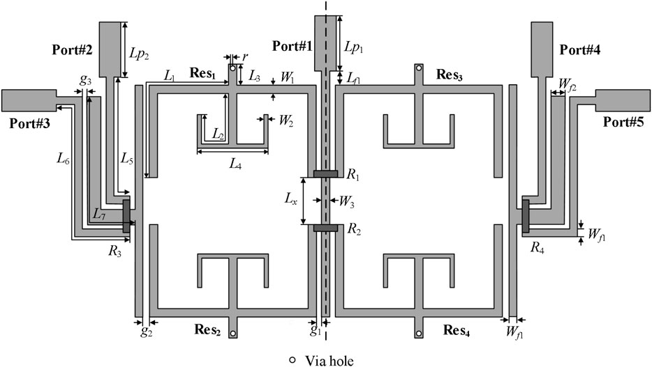
The configuration of the proposed four-way triple-band FPD is shown in Figure 1. As observed, it is mainly composed of four triple-mode resonators, two T-shaped coupled output lines, five microstrip input/output transmission lines, and four isolation resistors. In particular, the employed four triple-mode resonators are located symmetrically on both sides of the common open-ended input transmission line in this design, and two pairs of output transmission lines are placed at both sides of the two T-shaped coupled output lines, respectively. In addition, two of isolated resistors (R1, R2) are loaded between the inner adjacent arms of two pairs of resonators while the other two isolated resistors (R3, R4) connect the two open ends of the output line to achieve nice port-to-port isolation. It can distinctly see from the structure that the signal input from Port#1 is first transmitted along the open input line and then evenly coupled to the resonators on both sides of the input line to the T-shaped coupled lines, and finally coupled to output ports (Port#2, Port#3, Port#4, and Port#5) with equal power distribution. Based on the proposed symmetrical circuit structure, the couplings between the resonators and the output lines have the same amplitude and in-phase characteristics. In this way, the desired four-way triple-band filtering power division response can be achieved.
Design and Analysis of the Proposed Four-Way Triple-Band FPD
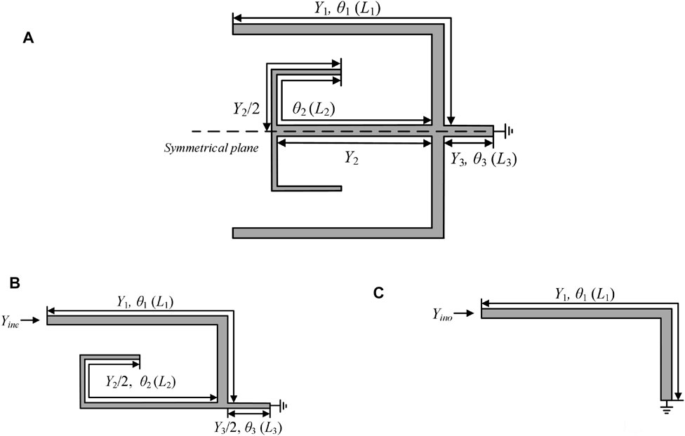
In this design, as shown in Figures 2A, a triple-mode net-type resonator is formed by connecting one net-type open-ended stub, one short-ended stub, and two open-ended stubs, which is inspired by [16, 17]. Because the employed resonator has a symmetrical structure with the reference to the symmetrical plane, the even-/odd-mode analysis method [18] can be applied in analyzing its resonance characteristics. With odd-/even-mode excitation, the symmetrical plane behaves as magnetic/electrical wall. The equivalent circuits for the resonator are shown in Figures 2B,C, respectively. According to transmission line theory, the input admittances of odd-/even-mode equivalent circuits are calculated as Eqs 1, 2:
where Yi (i = 1, 2, 3) denotes the characteristic admittance of each transmission line section.
Furthermore, the three resonance frequencies of even-/odd-mode can be roughly estimated as Eq. 5:
where f0 is the center frequency. By setting Yin,odd = Yin,even, an inherent transmission zero (TZ) frequency can be deduced by

FIGURE 2. Structure of triple-mode resonator and even-/odd-mode. (A) Entire resonator. (B) Even-mode equivalent circuit. (C) Odd-mode equivalent circuit.
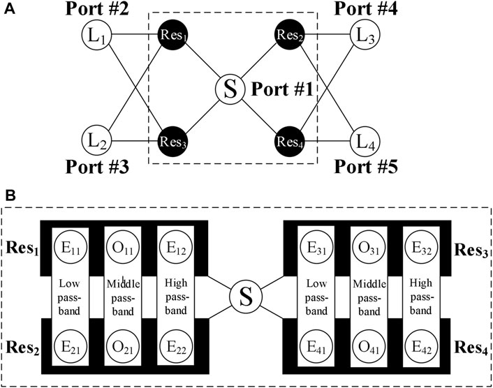
Figure 4 presents the coupling topology and mode distribution of the proposed four-way triple-band FPD. It can be seen from Figure 4A that an incident signal that is fed at Port #1 is divided into two same signals by symmetrically coupling to two pairs of identical triple-mode resonators. Then, by proper exciting the first three resonant modes of the triple-mode resonators and coupling them to the four output ports, four-way filtering power division is realized. In Figure 4A, S and L1/2/3/4 denote source and loads while Res1/2/3/4 represents the employed net-type triple-mode resonators. Among them, resonators Res1/2 and resonators Res3/4 as well as loads L1/2 and L3/4 are symmetrically arranged. Figure 4B is a schematic diagram of the contents of the dotted frame in Figure 4A, which describes detailed mode distribution for multi-band. It can be clearly seen that the corresponding mode contributes to each passband of the triple band. Specifically, each resonator of Res1/2/3/4 is composed of three resonance modes, which are even mode E11 (E21, E31, E41), odd mode O11 (O21, O31, O41), and even mode E12 (E22, E32, E42), respectively. Among them, the first even modes E11 (E31) and E21 (E41) of the resonator Res1 (Res3) and Res2 (Res4) constitute low passband response. In a similar way, the first odd modes O11 (O31) and O21 (O41) of the resonator Res1 (Res3) and Res2 (Res4) constitute middle passband response. Besides, the second even modes E12 (E32) and E22 (E42) of the resonator Res1 (Res3) and Res2 (Res4) constitute high passband response. Based on the above the coupling topology and mode distribution, a four-way triple-band filtering power divider can be initially implemented. Meanwhile, for achieving good port-to-port isolations, two isolated resistors are elaborately introduced between the inner adjacent arms of two pairs of resonators while the other two isolated resistors are properly placed between the adjacent output lines as shown in Figure 1.

FIGURE 4. The coupling topology and mode distribution. (A) The design coupling scheme of proposed FPD. (B) The modes consist of three passbands.
Implementation and Results
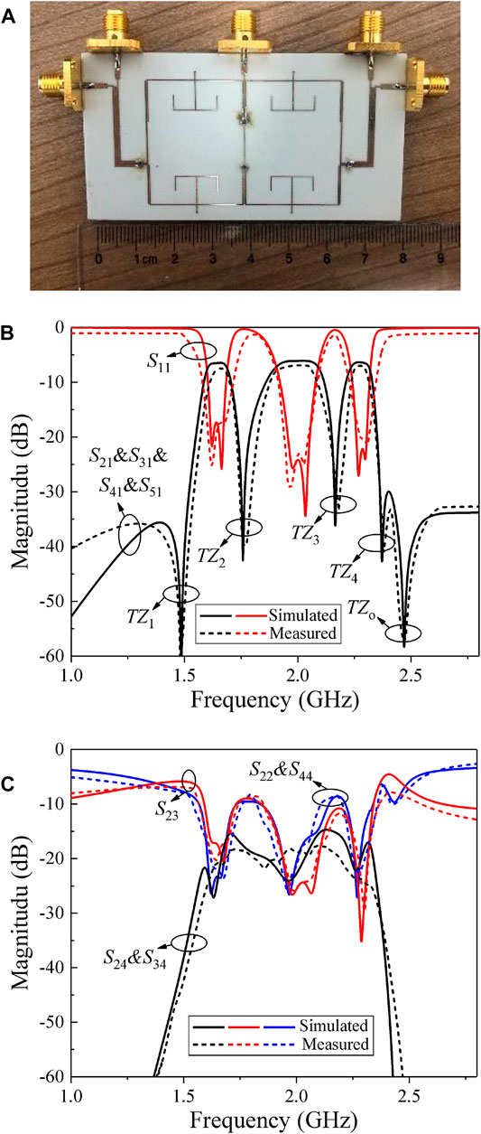
Based on the above analysis, one prototype four-way triple-band FPD was fabricated on a Rogers RO4003C substrate with a relative dielectric constant εr = 3.55, thickness h = 0.508 mm, and loss tangent tan δ = 0.0027. The photograph of the fabricated four-way triple-band FPD with size of 66.8 × 35.2 mm2 (0.83λg × 0.44λg) is shown in Figure 5A. The final optimal layout parameters (in mm) in Figure 1 are: L1 = 21.86, L2 = 15.62, L3 = 2.03, L4 = 10.82, L5 = 25.44, L6 = 27.86, L7 = 25.53, Lp = 6.28, Lf1 = 1.36, Lx = 10.81, W1 = 0.22, W2 = 0.18, W3 = 0.23, Wf1 = 0.32, Wf2 = 0.64, g1 = 0.14, g2 = 0.11, g3 = 0.1, r = 0.1, R1 = 2000 Ω, R2 = 1,000 Ω, R3 = 220 Ω, and R4 = 220 Ω. The frequency characteristic of the proposed four-way triple-band FPD was studied by the electromagnetic simulator HFSS and the network analyzer Agilent N5244A. The simulation and measured results are shown in Figures 5B,C. Due to the connection loss of the SMA connector, there is a certain discrepancy between the simulation results and the measurement ones. Results indicate that the proposed FPD works at the center frequency of 1.67, 2.10, and 2.26 GHz, with corresponding 3-dB fractional bandwidths of 7%, 12%, and 11%. In addition, as expected, five TZs are generated, at 1.48, 1.76, 2.16, 2.37, and 2.47 GHz, ensuring sharp roll-off skirt and out-of-band harmonic suppression. Meanwhile, the measured insertion losses (ILs) are 7.44, 6.92, 7.02 dB while input return losses (RLs) are better than 17.3, 23.1, and 20.2 for the three passbands, respectively. Besides, the output RLs are better than 17.1, 17.3, and 16.3 dB. Moreover, the three passbands exhibit higher than the 17.0, 16.3, and 17.8 dB isolation for each passband, respectively. Table 1 tabulates the performance comparison between the proposed four-way triple-band FPD and other reported works. It can be seen that our proposed FPD exhibits nice return loss, sharp frequency selectivity with multiple TZs, as well as high port-to-port isolations.

FIGURE 5. Measured and Simulated results of the four way triple-band FPD. (A) The photograph of the fabricated FPD. (B) Magnitudes of S11&S21&S31&S41&S51. (C) Magnitudes of S22&S44&S23&S24&S34.
Conclusion
In this letter, a novel triple-band four-way FPD with highly improved performance has been presented. After clearly analyzing its working mechanism, a four-way triple-band FPD is implemented with nice multi-band filtering performance and satisfactory port-to-port isolation. It is believed that the proposed design is very attractive for multi-way multi-band application in wireless multi-communication standard systems.
Data Availability Statement
The original contributions presented in the study are included in the article/Supplementary Material, further inquiries can be directed to the corresponding author.
Author Contributions
YL conducted extensive analysis and wrote parts of this paper. XZ gave assistance in the measurement and wrote parts of this paper. XS, XG, BX, XZ, and KP revised this paper.
Conflict of Interest
YL, XZ, XS, XG, BX, XZ, and KP were employed by Hengdian Electronics Co., Ltd.
Publisher’s Note
All claims expressed in this article are solely those of the authors and do not necessarily represent those of their affiliated organizations, or those of the publisher, the editors, and the reviewers. Any product that may be evaluated in this article, or claim that may be made by its manufacturer, is not guaranteed or endorsed by the publisher.
References
1. Lei Wu L, Zengguang Sun Z, Yilmaz H, Berroth M. A Dual-Frequency Wilkinson Power Divider. IEEE Trans Microwave Theor Techn. (2006) 54:278–84. doi:10.1109/tmtt.2005.860300
2. Guo L, Zhu H, Abbosh AM. Wideband Tunable In-phase Power Divider Using Three-Line Coupled Structure. IEEE Microw Wireless Compon Lett (2016) 26:404–6. doi:10.1109/lmwc.2016.2562058
3. Xu K-D, Xia S, Jiang Y, Guo Y-J, Liu Y, Wu R, et al. ‘Compact Millimeter-Wave On-Chip Dual-Band Bandpass Filter in 0.15-μm GaAs Technology’. IEEE J Electron Devices Soc (2022) 10:152–156. doi:10.1109/jeds.2022.3143999
4. Xu K-D, Lu S, Guo Y-J, Chen Q. Quasi-Reflectionless Filters Using Simple Coupled Line and T-Shaped Microstrip Structures. IEEE J Radio Freq Identif (2022) 6:54–63. doi:10.1109/jrfid.2021.3106664
5. Zhu H, Cheng Z, Guo YJ. Design of Wideband In-phase and Out-of-phase Power Dividers Using Microstrip-To-Slotline Transitions and Slotline Resonators. IEEE Trans Microwave Theor Techn. (2019) 67:1412–24. doi:10.1109/tmtt.2019.2897928
6. Zhang G, Liu Y, Wang E, Yang J. Multilayer Packaging SIW Three-Way Filtering Power Divider with Adjustable Power Division. IEEE Trans Circuits Syst (2020) 67(12):3003–7. doi:10.1109/tcsii.2020.2987327
7. Keshavarz. S, Abdipour A, Mohammadi A, Keshavarz R. ‘Design and Implementation of Low Loss and Compact Microstrip Triplexer Using CSRR Loaded Coupled Lines’. Aeu-int J Electron Commun (2019) 111:1–5. doi:10.1016/j.aeue.2019.152913
8. Chau W-M, Hsu K-W, Tu W-H. Filter-Based Wilkinson Power Divider. IEEE Microw Wireless Compon Lett (2014) 24:239–41. doi:10.1109/lmwc.2014.2299543
9. Zhang G, Wang X, Hong J-S, Yang J. A High-Performance Dual-Mode Filtering Power Divider with Simple Layout. IEEE Microw Wireless Compon Lett (2018) 28:120–2. doi:10.1109/lmwc.2018.2789821
10. Zhang G, Yang J, Zhao Y. Simple Wideband FPD with Sharp Passband Selectivity and Nice UWB Isolation. Electron Lett (2018) 54:217–9. doi:10.1049/el.2017.4213
11. Zhang G, Wang J, Zhu L, Wu W. Dual-Mode Filtering Power Divider with High Passband Selectivity and Wide Upper Stopband. IEEE Microw Wireless Compon Lett (2017) 27:642–4. doi:10.1109/lmwc.2017.2711556
12. Yang M, Wang J, Wang X, Wu W. Design of Wideband Four-Way Filtering Power Divider Based on SIW Loaded Square Patch Resonator. Electron Lett (2019) 55:389–91. doi:10.1049/el.2018.8058
13. Song K, Mo Y, Fan Y. Wideband Four-Way Filtering-Response Power Divider with Improved Output Isolation Based on Coupled Lines. IEEE Microw Wireless Compon Lett (2014) 24:674–6. doi:10.1109/lmwc.2014.2340992
14. Zhu H, Abbosh AM, Guo L. Wideband Four-Way Filtering Power Divider with Sharp Selectivity and Wide Stopband Using Looped Coupled-Line Structures. IEEE Microw Wireless Compon Lett (2016) 26:413–5. doi:10.1109/lmwc.2016.2562107
15. Zhu C, Xu J, Wu W. Microstrip Four-Way Reconfigurable Single/Dual/Wideband Filtering Power Divider with Tunable Frequency, Bandwidth, and PDR. IEEE Trans Ind Electron (2018) 65:8840–50. doi:10.1109/tie.2017.2787577
16. Zhang G, Qian Z, Yang J, Hong J-S. Wideband Four-Way Filtering Power Divider with Sharp Selectivity and High Isolation Using Coshared Multi-Mode Resonators. IEEE Microw Wireless Compon Lett (2019) 29:641–4. doi:10.1109/lmwc.2019.2936138
17. Zhang G, Qian Z, Yang J. Design of a Compact Microstrip Power-Divider Diplexer with Simple Layout. Electron Lett (2018) 54:1007–9. doi:10.1049/el.2018.0375
Keywords: filtering power divider (FPD), four-way, triple-band, multi-mode, isolation
Citation: Li Y, Zhou X, Sun X, Gu X, Xu B, Zhang X and Ping K (2022) A New Triple-Band Four-Way Filtering Power Divider With Highly Improved Performance. Front. Phys. 10:862516. doi: 10.3389/fphy.2022.862516
Received: 26 January 2022; Accepted: 16 February 2022;
Published: 17 May 2022.
Edited by:
Kai-Da Xu, Xi’an Jiaotong University, ChinaReviewed by:
Lei Guo, The University of Queensland, AustraliaXuedao Wang, Jinling Institute of Technology, China
Copyright © 2022 Li, Zhou, Sun, Gu, Xu, Zhang and Ping. This is an open-access article distributed under the terms of the Creative Commons Attribution License (CC BY). The use, distribution or reproduction in other forums is permitted, provided the original author(s) and the copyright owner(s) are credited and that the original publication in this journal is cited, in accordance with accepted academic practice. No use, distribution or reproduction is permitted which does not comply with these terms.
*Correspondence: Xiaohang Sun, WGlhb2hhbmdfU3VuX2hkbXdAMTI2LmNvbQ==
 Yibing Li
 Xin Zhou
 Xiaohang Sun
 Xiaojun Gu
 Bin Xu
 Xinde Zhang
 Kang Ping

