- 1State Key Laboratory of Precision Spectroscopy, School of Physics and Electronic Science, East China Normal University, Shanghai, China
- 2Collaborative Innovation Center of Extreme Optics, Shanxi University, Taiyuan, China
By using infrared to ultraviolet (IR-UV) femtosecond laser directing, periodic nanostructures were efficiently fabricated on an F-doped tin oxide (FTO) film with a thickness of 650 nm. The morphology of the nanostructures and duty cycle were studied in detail by changing the laser fluence and scanning speed, where three lasers with central wavelengths of 343, 515, and 1,030 nm were used in the experiments. Under the 515 nm laser irradiation with scanning speed of 0.01 mm/s and laser fluence of 23 mJ/cm2, the periods Λ is 172 nm, the ablated nanogroove with width w2 is 52 nm, the birefringence Δn reached a maximum of 0.21, and the phase retardance was up to 135 nm. The morphology of the nanostructures and the birefringence effects of the FTO film prepared by a femtosecond laser at wavelengths of 1,030 and 343 nm were also studied, where the phase retardance of the nanostructured FTO film was much lesser than for the 515 nm laser because the thickness of the nanoripples layer, and, thus, the duty cycle of periodic nanoripples was smaller. Finally, a large-area FTO film with periodic nanostructures was fabricated efficiently by direct laser writing using a 515 nm fs laser beam focused via a cylindrical lens, and demonstrated the characteristics of a quarter-wave plate for 532 nm light.
Introduction
Femtosecond laser-induced periodic surface structures (LIPSS) have been studied extensively for many types of materials, such as metals, semiconductors, dielectric solids, and thin films [1–14]. Owing to its versatility and flexibility, femtosecond LIPSS has become an efficient processing technique for fabricating functional devices, for structural color, absorption and luminescence enhancement, and large-area gratings [15–19].
Many studies have demonstrated that LIPSS fabricated by a femtosecond laser exhibits optical birefringence, which can be used as functional polarization components that find application in optical data storage, wave plates, and optical attenuators [20–23]. Experimental results have shown that materials with a high refractive index have good birefringence effects, such as amorphous silicon and silicon carbide [24, 25]. Recently, Cerkauskaite et al. fabricated periodic nanostructures on ITO films using a femtosecond laser. The nanostructured ITO film was found to have a strong birefringence effect Δn = 0.2, which is two orders of magnitude higher than that of fused quartz [26]. This method was further used to fabricate spatially varying polarization-sensitive optical elements, polarization, and multidimensional optical data storage elements [26].
F-doped tin oxide (FTO) is a tin oxide doped with fluorine. Similar to ITO, FTO films have the advantages of good transmittance for visible light, high UV absorption coefficient, and low resistivity [27–32]. Therefore, FTO thin films are widely used as transparent electrodes in solar cells and perovskite solar cells [33–35]. At present, the birefringence effect of FTO films with LIPSS layers has rarely been reported.
In this study, we report the birefringence of FTO films with periodic nanostructures induced by femtosecond lasers with central wavelengths of 343, 515, and 1,030 nm. The morphology of the nanostructures and the phase retardance of the FTO film were studied in detail by changing the laser fluence and scanning speed. Finally, a large-area FTO film with periodic nanostructures was fabricated efficiently by 515 nm laser direct writing and demonstrated the characteristics of a quarter-wave plate with 532 nm light.
Experimental
As is shown in Figure 1, a laser (Light Conversion, PHAROS) generated femtosecond laser pulse with central wavelengths of 343, 515, and 1,030 nm, pulse width of 250 fs, and repetition frequency of 5 kHz was used as the laser source. Firstly, the laser passed through two high mirrors, and then through shutter, half-wave plate and Glan prism. The laser irradiation time was controlled by a mechanical shutter, and the its fluence was adjusted using a half-wave plate and Glan prism. The laser was then divided into two beams in the beam splitter, in which the reflected light was used for processing. The laser beam was focused by a cylindrical lens with a focal length of 50 mm and was vertically incident onto the sample. The focal spot was 28 μm wide (diameter at 1/e2) and 4.0 mm long. At the same time, white light and a CCD were used to monitor laser processing in real time.
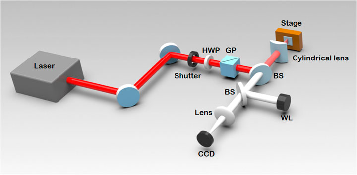
FIGURE 1. Schematic of the experimental set-up. HWP is a half-wave plate, GP is a Glan prism, BS is the beam splitter, and WL is the white light source.
An FTO film with a thickness of 650 nm was coated on a K9 glass substrate using the chemical vapor deposition method. The sample was mounted on an x-y-z electrical translation stage. After laser irradiation, the sample was cleaned in an ultrasonic bath in three steps, using isopropanol, acetone, and deionized water, respectively. Imaging of the surface morphology was performed using an optical microscope and a scanning electron microscope (SEM, S-4800 Cold-field SEM, and Hitachi).
The nanostructured FTO film was placed on an electric rotating table to measure the birefringence retardance, as shown in Figure 2. The 532 nm laser beam passes through the first Glan prism to generate linearly polarized light. Then, linearly polarized light is focused on the sample through a lens. The transmitted light is collected by a lens and incident on a detector through the second Glan prism, which works as an analyzer. The transmittance T can be expressed as T = P1/P2, where P1 is the laser power passing through the initial FTO film, and P2 is the laser power passing through the nanostructured FTO film. The transmittance T is a function of the rotation angle, which can be expressed as follows [36]:
where δ is the phase retardance of the FTO film, and θ is the angle between the fast axis of the FTO film and the first polarizer.
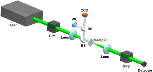
FIGURE 2. Schematic diagram of the measurement of the retardance. GP1 is the polarizer and GP2 is the analyzer, BS is the beam splitter, and WL is the white light source.
Experimental Results and Discussion
Birefringence of LIPSS Induced by 515 nm Femtosecond Laser
The formation of LIPSS by laser direct writing is a multi-pulse cumulative process, which greatly depends on the laser fluence and scanning speed [37, 38]. In the following, the formation of LIPSS induced by the 515 nm fs laser and the phase retardance were studied by changing the laser fluence and scanning speed.
Figures 3A–F show the SEM images of the LIPSS formed on the FTO film fabricated by a 515 nm fs laser at a scanning speed of 0.01 mm/s. When the laser fluence was less than 19 mJ/cm2, the laser was too weak to ablate the sample. When the laser fluence was increased to 20 mJ/cm2, very short and broken ripples formed on a part of the sample surface, and indicating that the ablation threshold of FTO film had been reached. After laser irradiation at 21 mJ/cm2, LIPSS appeared on the entire surface, excluding a few spots. Regular LIPSS formed on the entire film as the laser fluence increased to 23 mJ/cm2. The LIPSS is perpendicular to the direction of laser polarization, with periods much less than half of the laser wavelength, which is categorized as high-spatial-frequency LIPSS (HSFL) [12]. When the laser fluence was further increased to 27 mJ/cm2, some molten debris remained on the surface, indicating that HSFL begin to melt. These molten debris covered nearly one-third of the entire sample surface irradiated by a laser with a fluence of 31 mJ/cm2, as shown in Figure 3F.
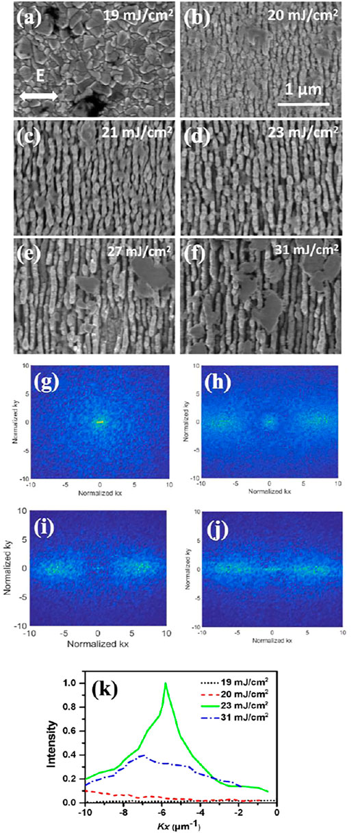
FIGURE 3. (A–F) SEM images of the nanostructured FTO film. (G–J) are 2D-FT images of LIPSS in (A,B,D, and F), respectively. (K) FT spectra at ky = 0 μm−1 in (G–J). Scanning speed is 0.01 mm/s.
Figures 3G–J show the 2D Fourier transformed (FT) images of Figures 3A,B,D,and F, respectively. To clearly demonstrate the regularity of the HSFL, the Fourier spectra for ky = 0 μm−1 are shown in Figure 3K. When the laser fluence is 23 mJ/cm2, the peak of the FT spectrum is at 5.8 μm−1, and the LIPSS period is approximately 172 nm. The FT spectra are much wider, and the peaks are lower for the HSFL irradiated by the other laser fluences, which means that the LIPSS are irregular.
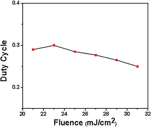
As shown in Figures 3A–F, we measured the size of the grooves and calculated the average values. The ripple periods were obtained according to the FT spectrum, and the duty cycle of the HSFL was calculated as the ratio of the groove width to the ripple period. Figure 4 shows the variation in the duty cycle of the HSFL with the laser fluence. It increases to 0.3 at a laser fluence of 23 mJ/cm2, and decreases to 0.25 as laser fluence increases to 31 mJ/cm2.
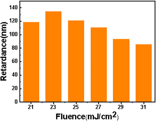
Figure 5 shows the retardance of the FTO film with HSFL varying with the laser fluence. When the laser fluence is 21 mJ/cm2, the retardance is 119 nm. When the laser fluence increases to 23 mJ/cm2, the phase retardance reaches a maximum of 135 nm. It is three times larger than that of the ITO film owing to the difference in the focusing lens and film thickness [26]. However, the phase retardance decreases with a higher laser fluence. When the laser fluence is 31 mJ/cm2, the retardance is only 83 nm.
The SEM images of the nanostructured FTO thin film with increasing scanning speed are shown in Figure 6. The HSFL is very clear, and the duty cycle is as large as 0.3 at a scanning speed of 0.01 mm/s (the corresponding laser shots per area of 14,000, which is equivalent to spatial pulse overlapping of 99.99%), as shown in Figure 6A. As the scanning speed increases, the HSFL becomes shorter and narrower, and the grooves became narrower, as shown in Figures 6B,C. This is because the cumulative laser pulses and deposited laser fluence decrease at each position. The ripples are only partly covered on the film when the scanning speed is larger than 0.08 mm/s. Only some very narrow and shallow short ripples appear on the surface of the FTO film at a speed of 0.2 mm/s (the corresponding laser shots per area of 700, which is equivalent to spatial pulse overlapping of 99.8%).
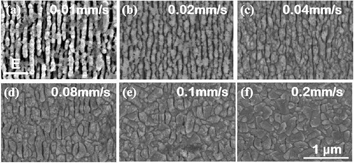
FIGURE 6. SEM images of FTO thin films irradiated by a 515 nm fs laser at different scanning speeds. The laser fluence is 23 mJ/cm2.
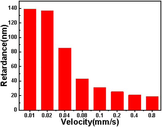
Figure 7 shows the relationship between the phase retardance and the laser scanning speed. It can be observed that the irradiated FTO thin film exhibits lower retardance at higher scanning speeds. In summary, the experimental results showed that the birefringence effect of the FTO film reached a maximum value of 135 nm when the laser fluence was 23 mJ/cm2 and the scanning speed was 0.01 mm/s.
Birefringence Effect of LIPSS Layer
The principle of the birefringence effect of the FTO film with LIPSS is essentially the same as that of a uniaxial anisotropic material. The phase retardance of transmitted light (φ) can be directly determined from the thickness of the LIPSS layer (d) and the birefringence effect (Δn) [19, 36]:
where ∆n = ne-no represents the difference between the refractive indices for ordinary and extraordinary light of the FTO film. In order to calculate ∆n for the FTO film, the LIPSS layer can be considered to consist of a periodic alternating arrangement of the unablated FTO nanoplane with width w1 and the ablated nanogroove with width w2 [19]. Therefore, the refractive indices for ordinary light and extraordinary light satisfy the following relationship [39]:
where f = w2/(w1 + w2) is the duty cycle, and n1 and n2 are the refractive indices of unmodified and modified FTO, respectively [24, 36]. The refractive index n1 of FTO is 2.24 for 515 nm light [40]. The modified material was air and n2 = 1.0. The ordinary refractive index no is approximately equal to the refractive index n1 = 2.24 of FTO without nanostructures, so the expression ne can be obtained according to Eq. 3
The difference of refractive index Δn can be written as
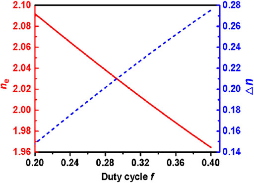
According to Eq. 5, the birefringence effect of the nanostructured FTO film depends mainly on n1, n2, and duty cycle f. Figure 8 shows the relationship between ne, Δn, and the duty ratio f. It can be seen that when duty cycle increases from 0.2 to 0.4, ne decreases from 2.09 to 1.96, and Δn increases from 0.15 to 0.27 correspondingly. This demonstrates that the birefringence effect increases with the duty cycle, namely, with the difference in refractive index Δn, which can well explain the similar changing trends of the duty cycle and retardance of the FTO film in Figures 4, 5.
The period of HSFL formed on the surface of the FTO film was 172 nm, and the duty cycle w2/Λ was 0.3 when the laser fluence was 23 mJ/cm2 and the scanning speed was 0.01 mm/s. The difference in the refractive index Δn of the FTO film with HSFL can be calculated to be 0.21, according to periods Λ and w2. The retardance of the FTO film with HSFL was 135 nm (quantitatively measured by a 532 nm laser), and the thickness of the LIPSS layer was calculated to be approximately 640 nm using Eq. 2.
To further study the birefringence effect, the thickness of the LIPSS layer in the FTO film was studied. FTO films with regular LIPSS were immersed in a 1% HF solution at 24°C and etched for different times (10, 20, 25, and 30 s). After etching, the samples were washed with deionized water and dried. The surface morphology and depth of the FTO film were measured by SEM and a step profiler, respectively.
Figure 9 shows SEM images of the FTO film with different etching times. When the etching time is 10 s, the etching depth is 322 nm, as shown in Figure 9A. The ripples of HSFL became unclear as the etching time increased to 20 s, and the etching depth reached 600 nm, as shown in Figures 9B,E. When the etching time was increased to 25 s, the ripples almost completely disappeared, and the etching depth reached 700 nm, as shown in Figure 9C. These results indicate that the thickness of the HSFL layer formed on the FTO film was approximately 650 nm. This value is very close to the calculated result of 640 nm owing to the birefringence effect. When the etching time was increased to 30 s, the SEM image showed that the glass substrate was exposed, as shown in Figure 9D.
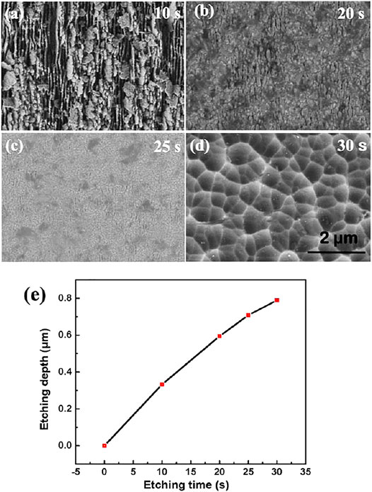
FIGURE 9. (A–D) SEM images of nanostructured FTO films with different etching times. (E) The depths changing with the etching time.
Birefringence of LIPSS Induced by 1,030 nm Femtosecond Laser
We have done the variation of retardance at 343, 515, and 1,030 nm with different fluence and scanning speed respectively. After analysis, we can find that the best retardance corresponds to a scan speed of 0.01 mm/s at three laser wavelengths. Therefore, we only discuss the results at 1030 and 343 nm wavelengths at a scanning speed of 0.01 mm/s.
Figure 10 shows the retardance of FTO thin films after irradiation with a 1,030 nm laser at different fluences. The retardance increases from 56 to 96 nm when the laser fluence increases from 77 mJ/cm2 to 89 mJ/cm2. When the laser fluence continues to increase, the retardance begins to decrease slowly. When the laser fluence is 92 mJ/cm2, the retardance of the nanostructured FTO film decreases to 88 nm. The experimental results at a laser fluence of 89 mJ/cm2 and scanning speed of 0.01 mm/s were studied in detail. The period and groove width of the HSFL were measured to be 300 and 108 nm, respectively. The duty cycle was 0.36, and the difference in the refractive index Δn was approximately 0.2, according to Eq. 5. The difference in the refractive index Δn is less than that in the case of 515 nm, leading to a smaller retardance. Moreover, the thickness of the HSFL layer was measured to be approximately 480 nm, which is another reason for the smaller retardance with the 1,030 nm laser.

FIGURE 10. The retardance as a function of laser fluence from a 1,030 nm laser. The scanning speed is 0.01 mm/s.
Birefringence of LIPSS Induced by 343 nm Femtosecond Laser
Comparing the birefringence effects of the FTO film after irradiation by the 515 and 1,030 nm fs lasers, it was observed that the widths of the grooves were similar; the duty cycle for the 515 nm laser was larger because the period of the HSFL was smaller. According to the relationship between the birefringence effect (Δn) and the duty cycle in Figure 9, the birefringence effect increases with the duty cycle. Therefore, by using a laser with a shorter wavelength, we predicted that the duty cycle and the birefringence effect would be larger because the HSFL formed on the FTO film would have a shorter period [24, 33]. A femtosecond laser with a wavelength of 343 nm was used to fabricate the HSFL on the FTO film.
Figure 11A shows the SEM image of the laser-induced nanostructures on the FTO film for a scanning speed of 0.01 mm/s. For the 343 nm laser with a fluence of 13 mJ/cm2, regular HSFL formed over the entire ablation area. The ripple period is approximately 126 nm, which is less than the value of 172 nm induced by the 515 nm laser. Figure 11B shows the retardance varying with the 343 nm laser fluence. When the laser fluence increases from 9 to 13 mJ/cm2, the retardance increases from 35 to 47 nm. The birefringence retardance decreases rapidly to 33 nm as the laser fluence increases to 22 mJ/cm2. Surprisingly, the retardation produced by the 343 nm laser is only 47 nm, which is much smaller than the optimal value of 135 nm induced by the 515 nm laser. The width of the groove was measured, and Δn was calculated to be 0.21, which is nearly equal to the value for the 515 nm laser. The thickness of the HSFL layer was measured to be approximately 230 nm, which is much smaller than the value of 650 nm for the 515 nm laser. The very thin HSFL layer is the main reason for the smaller retardation produced by the 343 nm laser.
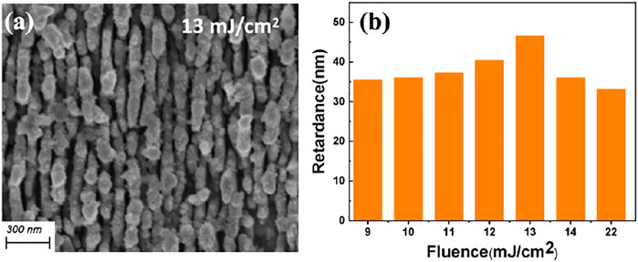
FIGURE 11. (A) SEM image of the nanostructured FTO film prepared by 343 nm laser with a fluence of 0.13 J/cm2. (B) The retardance as a function of laser fluence. The scanning speed is 0.01 mm/s.
For the FTO film, the extinction coefficients k are 0.11 and 0.055 for 343 and 515 nm light, respectively [40]. Accordingly, the penetration depth, d = λ/4πk, is only 248 nm for the 343 nm laser, which is much less than the result of 746 nm for the 515 nm laser. As a result, the thickness of the HSFL layer fabricated by the 343 nm laser is much smaller than that for the 515 nm laser, as well as the retardance.
The transmittance and absorptivity of FTO films at 343, 515, and 1,030 nm are very different [41], so the laser fluence required to process LIPSS is different at the same scanning speed. By comparing the experimental results using a femtosecond laser with UV to IR wavelengths, the retardance of the FTO film fabricated by the 515 nm laser is the largest, which is more suitable for fabricating birefringence optical elements.
Quarter-Wave Plate for 532 nm Light
An HSFL layer with an area of 10 × 10 mm was prepared on the FTO film using a 515 nm fs laser with a fluence of 23 mJ/cm2 and a scanning speed of 0.01 mm/s. The spacing between adjacent scans was 1 mm. After laser fabrication, the FTO film was mounted on a rotating mirror frame and placed between two mutually perpendicular polarizers to form a light attenuator, as shown in Figure 2. By rotating the FTO film with HSFL, the relationship between the transmittance and rotation angle was obtained, as shown in Figure 12A. The transmittance changes in the range of 0–50%, which is very consistent with the theoretical prediction for a birefringence element with a phase rate of 135 nm, indicating that the HSFL layer on the FTO film has good birefringence characteristics. Here, light transmission through the unprocessed FTO film was set to 1.
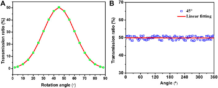
FIGURE 12. (A) Variation of transmission ratio with the rotation angle of HSFL, (B) with the rotation angle of the analyzer GP2. The hole squares are experimental results, and the solid red curve is the theoretical value of a quarter-wave plate.
The maximum retardance of the nanostructured FTO film was 135 nm, which was similar to a quarter wave plate for 532 nm light. Rotating the sample so that the ripples of the HSFL are oriented at a 45° angle to the polarizer GP1. As shown in Figure 12B, when analyzer GP2 was rotated from 0 to 360°, the detected light intensity hardly changed, indicating that the linearly polarized light became circularly polarized after passing through the nanostructured FTO film. These experimental results demonstrate that the FTO film with HSFL can function as a quarter-wave plate for 532 nm light.
Conclusion
This paper reports the fabrication of HSFL and birefringence effects in FTO films by using a femtosecond laser directed at wavelengths of 343, 515, and 1,030 nm. The morphology and duty cycle of the HSFL were studied in detail by changing the laser fluence and scanning speed. The difference in the refractive index Δn reached a maximum of 0.21, and the phase retardance was up to 135 nm when the FTO film was irradiated by a 515 nm laser with a fluence of 23 mJ/cm2 at a scanning speed of 0.01 mm/s. By etching the FTO film at different times, the experimental results showed that the thickness of the HSFL layer was approximately 650 nm, which is very close to the value according to birefringence theory. The morphology of the HSFL and the birefringence effects of the FTO film prepared using 1,030 and 343 nm lasers were also studied. The phase retardances were both much less than for the 515 nm laser. Owing to the much stronger absorption for the 343 and 1,030 nm lasers, the penetration depths in the FTO film were much smaller. Therefore, the thickness of the HSFL layer was much lesser, which reduced the phase retardance. A large-area FTO film with HSFL was fabricated efficiently by a 515 nm laser focused via a cylindrical lens, and demonstrated the characteristics of a quarter-wave plate with 532 nm light.
Data Availability Statement
The original contributions presented in the study are included in the article/Supplementary Material, further inquiries can be directed to the corresponding authors.
Author Contributions
FZ: Experiment inquiry, Investigation, Data Curation, Writing - Original Draft. LC: Conceptualization, Visualization, Formal analysis. YZ: Data Curation, Writing - Review & Editing. QJ: Writing - Review & Editing. DF: Writing - Review & Editing. SZ: Writing - Review & Editing. TJ: Conceptualization, Writing - Review & Editing. ZS: Writing - Review & Editing. HX: Writing - Review & Editing. FZ and LC contributed equally to this article, and they are co-first authors of this paper.
Funding
This work was supported by the National Natural Science Foundation of China (12074123, 11804227, and 91950112), and the Foundation of ‘Manufacturing beyond limits’ of Shanghai.
Conflict of Interest
The authors declare that the research was conducted in the absence of any commercial or financial relationships that could be construed as a potential conflict of interest.
Publisher’s Note
All claims expressed in this article are solely those of the authors and do not necessarily represent those of their affiliated organizations, or those of the publisher, the editors and the reviewers. Any product that may be evaluated in this article, or claim that may be made by its manufacturer, is not guaranteed or endorsed by the publisher.
References
1. Dufft D, Rosenfeld A, Das SK, Grunwald R, Bonse J. Femtosecond Laser-Induced Periodic Surface Structures Revisited: a Comparative Study on ZnO. J Appl Phys (2009) 105(3):034908. doi:10.1063/1.3074106
2. Sakabe S, Hashida M, Tokita S, Namba S, Okamuro K. Mechanism for Self-Formation of Periodic Grating Structures on a Metal Surface by a Femtosecond Laser Pulse. Phys Rev B (2009) 79(3):033409. doi:10.1103/physrevb.79.033409
3. Sedao X, Shugaev MV, Wu C, Douillard T, Esnouf C, Maurice C, et al. Growth Twinning and Generation of High-Frequency Surface Nanostructures in Ultrafast Laser-Induced Transient Melting and Resolidification. ACS Nano (2016) 10(7):6995–7007. doi:10.1021/acsnano.6b02970
4. Huang J, Jiang L, Li X, Zhou S, Gao S, Li P, et al. Controllable Photonic Structures on Silicon-On-Insulator Devices Fabricated Using Femtosecond Laser Lithography. ACS Appl Mater Inter (2021) 13(36):43622–31. doi:10.1021/acsami.1c11292
5. Fuentes-Edfuf Y, Sánchez-Gil JA, Florian C, Giannini V, Solis J, Siegel J. Surface Plasmon Polaritons on Rough Metal Surfaces: Role in the Formation of Laser-Induced Periodic Surface Structures. ACS Omega (2019) 4(4):6939–46. doi:10.1021/acsomega.9b00546
6. Jia TQ, Chen HX, Huang M, Zhao FL, Qiu JR, Li RX, et al. Formation of Nanogratings on the Surface of a ZnSe crystal Irradiated by Femtosecond Laser Pulses. Phys Rev B (2005) 72(12):125429. doi:10.1103/physrevb.72.125429
7. Garcia-Lechuga M, Puerto D, Fuentes-Edfuf Y, Solis J, Siegel J. Ultrafast Moving-Spot Microscopy: Birth and Growth of Laser-Induced Periodic Surface Structures. ACS Photon (2016) 3(10):1961–7. doi:10.1021/acsphotonics.6b00514
8. Zhang Y, Cheng K, Cao K, Jiang Q, Chen T, Zhang S, et al. Periodic Subwavelength Ripples on a Si Surface Induced by a Single Temporally Shaped Femtosecond Laser Pulse: Enhanced Periodic Energy Deposition and Reduced Residual thermal Effect. J Phys D: Appl Phys (2021) 54(38):385106. doi:10.1088/1361-6463/ac0f20
9. Wang L, Xu B-B, Cao X-W, Li Q-K, Tian W-J, Chen Q-D, et al. Competition between Subwavelength and Deep-Subwavelength Structures Ablated by Ultrashort Laser Pulses. Optica (2017) 4(6):637–42. doi:10.1364/optica.4.000637
10. Liu J, Jia X, Wu W, Cheng K, Feng D, Zhang S, et al. Ultrafast Imaging on the Formation of Periodic Ripples on a Si Surface with a Prefabricated Nanogroove Induced by a Single Femtosecond Laser Pulse. Opt Express (2018) 26(5):6302–15. doi:10.1364/oe.26.006302
11. Geng J, Fang X, Zhang L, Yao G, Xu L, Liu F, et al. Controllable Generation of Large-Scale Highly Regular Gratings on Si Films. gxjzz (2021) 2(3):273–81. doi:10.37188/lam.2021.022
12. Huang M, Zhao F, Cheng Y, Xu N, Xu Z. Origin of Laser-Induced Near-Subwavelength Ripples: Interference between Surface Plasmons and Incident Laser. ACS Nano (2009) 3(12):4062–70. doi:10.1021/nn900654v
13. Lou K, Qian J, Shen D, Wang H, Ding T, Wang G, et al. Recording, Erasing, and Rewriting of Ripples on Metal Surfaces by Ultrashort Laser Pulses. Opt Lett (2018) 43(8):1778–81. doi:10.1364/ol.43.001778
14. Jiao L, Kong D, Zhang X, Wang H, Dai Y, Song J. Ripple Period Adjustment on SiC Surface Based on Electron Dynamics Control and its Polarization Anisotropy. Appl Phys A (2021) 127(1):1–9. doi:10.1007/s00339-020-04181-2
15. Vorobyev AY, Guo C. Direct Femtosecond Laser Surface Nano/microstructuring and its Applications. Laser Photon Rev (2013) 7(3):385–407. doi:10.1002/lpor.201200017
16. Xiong P, Jia T, Jia X, Feng D, Zhang S, Ding L, et al. Ultraviolet Luminescence Enhancement of ZnO Two-Dimensional Periodic Nanostructures Fabricated by the Interference of Three Femtosecond Laser Beams. New J Phys (2011) 13(2):023044. doi:10.1088/1367-2630/13/2/023044
17. Zhang Y, Jiang Q, Cao K, Chen T, Cheng K, Zhang S, et al. Extremely Regular Periodic Surface Structures in a Large Area Efficiently Induced on Silicon by Temporally Shaped Femtosecond Laser. Photon Res (2021) 9(5):839–47. doi:10.1364/prj.418937
18. Cao K, Chen L, Wu H, Liu J, Cheng K, Li Y, et al. Large-area Commercial-Grating-Quality Subwavelength Periodic Ripples on Silicon Efficiently Fabricated by Gentle Ablation with Femtosecond Laser Interference via Two Cylindrical Lenses. Opt Laser Tech (2020) 131:106441. doi:10.1016/j.optlastec.2020.106441
19. Wu H, Jiao Y, Zhang C, ChenZhu S, YangWu LD, Li J, et al. Large Area Metal Micro-/nano-groove Arrays with Both Structural Color and Anisotropic Wetting Fabricated by One-step Focused Laser Interference Lithography. Nanoscale (2019) 11(11):4803–10. doi:10.1039/c8nr09747j
20. Taylor R, Hnatovsky C, Simova E. Applications of Femtosecond Laser Induced Self-Organized Planar Nanocracks inside Fused Silica Glass. Laser Photon Rev (2008) 2(1-2):26–46. doi:10.1002/lpor.200710031
21. Shimotsuma Y, Sakakura M, Kazansky PG, Beresna M, Qiu J, Miura K, et al. Ultrafast Manipulation of Self-Assembled Form Birefringence in Glass. Adv Mater (2010) 22(36):4039–43. doi:10.1002/adma.201000921
22. Drevinskas R, Kazansky PG. High-performance Geometric Phase Elements in Silica Glass. APL Photon (2017) 2(6):066104. doi:10.1063/1.4984066
23. Drevinskas R, Gecevičius M, Beresna M, Bellouard Y, Kazansky PG. Tailored Surface Birefringence by Femtosecond Laser Assisted Wet Etching. Opt Express (2015) 23(2):1428–37. doi:10.1364/oe.23.001428
24. Drevinskas R, Beresna M, Zhang J, Kazanskii AG, Kazansky PG. Ultrafast Laser-Induced Metasurfaces for Geometric Phase Manipulation. Adv Opt Mater (2017) 5(1):1600575. doi:10.1002/adom.201600575
25. Song J, Dai Y, Tao W, Gong M, Ma G, Zhao Q, et al. Surface Birefringence of Self-Assembly Periodic Nanostructures Induced on 6H-SiC Surface by Femtosecond Laser. Appl Surf Sci (2016) 363:664–9. doi:10.1016/j.apsusc.2015.12.096
26. Cerkauskaite A, Drevinskas R, Solodar A, Abdulhalim I, Kazansky PG. Form-birefringence in ITO Thin Films Engineered by Ultrafast Laser Nanostructuring. ACS Photon (2017) 4(11):2944–51. doi:10.1021/acsphotonics.7b01082
27. Remes Z, Vanecek M, Yates HM, Evans P, Sheel DW. Optical Properties of SnO2:F Films Deposited by Atmospheric Pressure CVD. Thin Solid Films (2009) 517(23):6287–9. doi:10.1016/j.tsf.2009.02.109
28. Yang JK, Liang B, Zhao MJ, Gao Y, Zhang FC, Zhao HL. Reference of Temperature and Time during Tempering Process for Non-stoichiometric FTO Films. Sci Rep (2015) 5(1):15001–6. doi:10.1038/srep15001
29. Manceriu LM, Maho A, Labrugere C, Tixhon E, Schrijnemakers A, Rougier A, et al. Influence of Quenching on the Opto-Electronic Properties of F:SnO2 Layers. ACS Omega (2020) 5(25):14999–5006. doi:10.1021/acsomega.0c00589
30. Wang X, Wang X, Di Q, Zhao H, Liang B, Yang J. Mutual Effects of Fluorine Dopant and Oxygen Vacancies on Structural and Luminescence Characteristics of F Doped SnO2 Nanoparticles. Materials (2017) 10(12):1398. doi:10.3390/ma10121398
31. Thomas R, Mathavan T, Jothirajan MA, Somaily HH, Zahran HY, Yahia IS. An Effect of Lanthanum Doping on Physical Characteristics of FTO Thin Films Coated by Nebulizer spray Pyrolysis Technique. Opt Mater (2020) 99:109518. doi:10.1016/j.optmat.2019.109518
32. Way A, Luke J, Evans AD, Li Z, Kim J-S, Durrant JR, et al. Fluorine Doped Tin Oxide as an Alternative of Indium Tin Oxide for Bottom Electrode of Semi-transparent Organic Photovoltaic Devices. AIP Adv (2019) 9(8):085220. doi:10.1063/1.5104333
33. Baek W-H, Choi M, Yoon T-S, Lee HH, Kim Y-S. Use of Fluorine-Doped Tin Oxide Instead of Indium Tin Oxide in Highly Efficient Air-Fabricated Inverted Polymer Solar Cells. Appl Phys Lett (2010) 96(13):133506. doi:10.1063/1.3374406
34. Tseng S-F, Hsiao W-T, Huang K-C, Chiang D. The Effect of Laser Patterning Parameters on Fluorine-Doped Tin Oxide Films Deposited on Glass Substrates. Appl Surf Sci (2011) 257(21):8813–9. doi:10.1016/j.apsusc.2011.04.055
35. Kwak D-J, Moon B-H, Lee D-K, Park C-S, Sung Y-M. Comparison of Transparent Conductive Indium Tin Oxide, Titanium-Doped Indium Oxide, and Fluorine-Doped Tin Oxide Films for Dye-Sensitized Solar Cell Application. J Electr Eng Tech (2011) 6(5):684–7. doi:10.5370/jeet.2011.6.5.684
36. Chen L, Cao K, Liu J, Jia T, Li Y, Zhang S, et al. Surface Birefringence of Regular Periodic Surface Structures Produced on Glass Coated with an Indium Tin Oxide Film Using a Low-Fluence Femtosecond Laser through a Cylindrical Lens. Opt Express (2020) 28(20):30094–106. doi:10.1364/oe.402037
37. Liu J, Jia T, Zhou K, Feng D, Zhang S, Zhang H, et al. Direct Writing of 150 Nm Gratings and Squares on ZnO crystal in Water by Using 800 Nm Femtosecond Laser. Opt Express (2014) 22(26):32361–70. doi:10.1364/oe.22.032361
38. Chen L, Cao K, Cao K, Li Y, Liu J, Zhang S, et al. Large-area Straight, Regular Periodic Surface Structures Produced on Fused Silica by the Interference of Two Femtosecond Laser Beams through Cylindrical Lens. Oea (2021) 4(12):200036. doi:10.29026/oea.2021.200036
40. Ameur SB, Barhoumi A, Bel hadjltaief H, Mimouni R, Duponchel B, Leroy G, et al. Physical Investigations on Undoped and Fluorine Doped SnO2 Nanofilms on Flexible Substrate along with Wettability and Photocatalytic Activity Tests. Mater Sci Semiconductor Process (2017) 61:17–26. doi:10.1016/j.mssp.2016.12.019
Keywords: birefringence effect, periodic nanostructures, phase retardance, femtoseocond laser, FTO film
Citation: Zhang F, Chen L, Zhang Y, Jiang Q, Feng D, Zhang S, Jia T, Sun Z and Xu H (2022) High-Performance Birefringence of Periodic Nanostructures in FTO Thin Film Fabricated by IR-UV Femtosecond Laser. Front. Phys. 10:861389. doi: 10.3389/fphy.2022.861389
Received: 24 January 2022; Accepted: 28 February 2022;
Published: 16 March 2022.
Edited by:
Ye Dai, Shanghai University, ChinaReviewed by:
Gopala Krishna Podagatlapalli, Gandhi Institute of Technology and Management (GITAM), IndiaAli Sami Alnaser, American University of Sharjah, United Arab Emirates
Copyright © 2022 Zhang, Chen, Zhang, Jiang, Feng, Zhang, Jia, Sun and Xu. This is an open-access article distributed under the terms of the Creative Commons Attribution License (CC BY). The use, distribution or reproduction in other forums is permitted, provided the original author(s) and the copyright owner(s) are credited and that the original publication in this journal is cited, in accordance with accepted academic practice. No use, distribution or reproduction is permitted which does not comply with these terms.
*Correspondence: Tianqing Jia, dHFqaWFAcGh5LmVjbnUuZWR1LmNu; Yuchan Zhang, eWN6aGFuZzE5OTVAMTYzLmNvbQ==
†These authors have contributed equally to this work and share first authorship
 Fengzhuo Zhang1†
 Long Chen
 Yuchan Zhang