 Bai Cao Pan
 Ben Jian Guo1
 Ping Yu
- 1Key Laboratory of RF Circuits and System Ministry of Education, School of Electronics and Information, Hangzhou Dianzi University, Hangzhou, China
- 2State Key Laboratory of Millimeter Waves, Southeast University, Nanjing, China
A leaky-wave antenna (LWA) realizes radiation of travelling wave along guiding structures. Periodic modulation is an effective approach to turn non-radiating modes into radiating modes. A high-efficient LWA based on spoof surface plasmon polaritons (SSPPs) loaded with parasitic patch array is proposed. Sinusoidal modulation is used for the radiation of SSPPs, while parasitic array mitigates the open stopband (OSB) effect. A prototype is fabricated and measured. The measured and simulated results agree well with each other. Such design shows wide angle coverage of 83
Introduction
Leaky-wave antennas (LWAs) was first introduced by Hansen in 1940, consisting of a slotted rectangular waveguide [1]. Since then, great improvements have been achieved in such field, taking advantages of low profile, wide frequency scanning coverage and ease of fabrication [2]. LWAs are popular in microwave designs because conical beam with good directivity related to frequency is achieved without complex feeding network. In recent years, they have been used in high-resolution radar systems, conformal antennas on aircraft, satellites, and guiding systems.
Spoof surface plasmon polaritons (SSPPs) are novel guiding modes excited on the surface of periodic metamaterial structures. Such modes mimic the dispersion property of surface plasmon polaritons (SPPs) that only exist in optical or near-infrared bands. SSPPs shows unique properties of low-pass, high field confinement, and shorter operating wavelength, which provides great reference to improve traditional microwave circuits and systems. In 2014, broadband excitement of SSPPs is reported, which makes great contributions to researches of SSPPs [3]. Since then, a series of passive and active functional devices based on SSPPs were reported [4–8].
However, the near electric field of SSPP modes locates around the metallic structure of the SSPP waveguides during propagation. It decays exponentially with the increasing distance away from the waveguide. Such distribution ensures low cross-talk between devices while increasing difficulties in designing radiation components. In order to turn the non-radiating mode into a radiating mode, periodical modulation and parasitic radiating patches are used. SSPP could work as excitation of certain patches to achieve effective radiation. Two rows of circular patch arrays were excited by SSPP transmission line with both perfect electric conductor (PEC) and artificial magnetic conductor (AMC) [9]. A single-beam scanning range of 40
In this paper, a highly efficient LWA is proposed for wide beam scanning coverage from backward to forward. Periodically modulated grooves are used for the radiation of SSPP mode. And parasitic patch array is added inside the complementary SSPP line to improve radiation efficiency and mitigate the OSB effect.
Radiation of SSPPs
As a kind of TM surface modes, the surface impedance of SSPP mode could be obtained from its dispersion property according to the surface impedance theory. For SSPP mode, electric field decays exponentially with the distance away from the waveguide. The wavenumber along the direction perpendicular to the structure is imaginary. Thus, the wavenumber in transmission direction is real and it is larger than the that in free space. The surface impedance of SSPP could be expressed as:
where
The wavenumber of SSPP
where
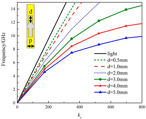
FIGURE 1. The wavenumber
According to the radiation theory of LWA, frequency scanning is valid as long as the condition of
where
The center frequency of the proposed radiator is designed to be around 9 GHz. Since the wavenumber of SSPP is dispersive, the surface impedance under different groove depths at 9 GHz is collected and shown in Figure 2. Since the cut-off frequency would be below 9 GHz when depth exceeds 6 mm. The maximum of the depth used is 5 mm. And the minimum of the depth is 0.5 mm. The surface impedance changes from 229
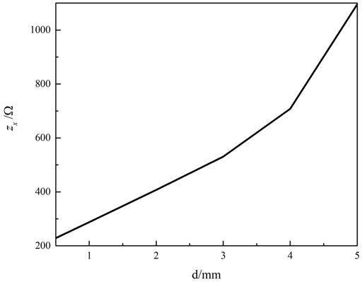
FIGURE 2. Surface impedance of SSPP corresponding to different groove depth d.
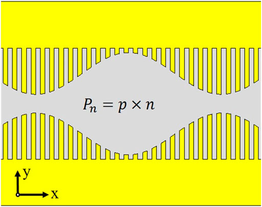
FIGURE 3. The structure of the periodic modulated composite SSPP unit.
The modulated n-order space harmonics of the average wavenumber is shown in Figure 4. Most harmonics locate outside the symmetrical light axis. Within band from 6 to 10.5 GHz (blue marked area), only the -first order harmonic locates in the fast wave area. Good frequency scanning could be realized. Within band from 10.5 to 14 GHz (orange marked area), both -first and -2nd order harmonics locates in the fast wave area. In such circumstance, radiation beam would split into two lobes in both backward and forward directions. The efficiency and radiation pattern would be affected. So the antenna is designed for band in which only -first order harmonic works.
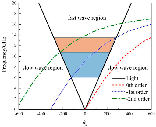
FIGURE 4. The dispersion relationship of space harmonics.
Periodic extension of the composite unit forms a high-performance leaky-wave radiation. The S parameters of such 2-port device is shown in Figure 5. Backward and forward frequency scanning are achieved around 8 and 9.5 GHz. However, within the operating band, a clearly uplift around 9 GHz is observed due to the OSB effect. The reflection at 9 GHz reaches -3.5 dB, which means most of the energy is reflected back to input. The radiation efficiency is damaged.
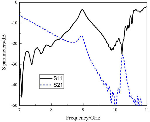
FIGURE 5. The simulated S parameters of the LWA based on SSPP.
Improved Performance With Parasitic Patch Array
In order to improve the broadside radiation efficiency, parasitic circular patch array is introduced. The patches are excited by the SSPP mode inside the transmission structure and provide extra radiation. The operating wavelength of the SSPP transmission line can be obtained from the modulated average wavenumber as
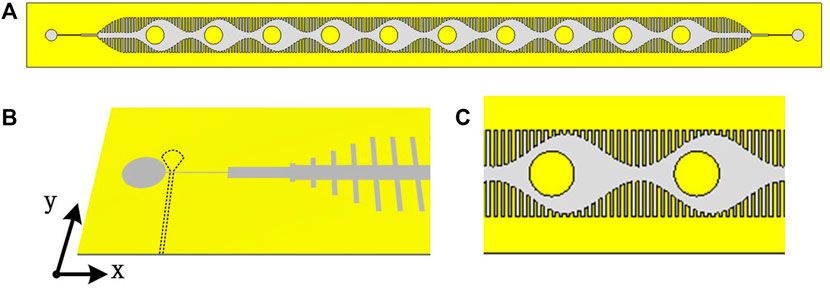
FIGURE 6. Schematic structure of (A) the proposed device, (B) the feeding network and (C) the composite unit.
The voltage standing wave ratio (VSWR) of the design with and without parasitic patches are compared in Figure 7. Within the whole operating band, the design with parasitic patches keeps around 1.4, and the significant peak disappeared.
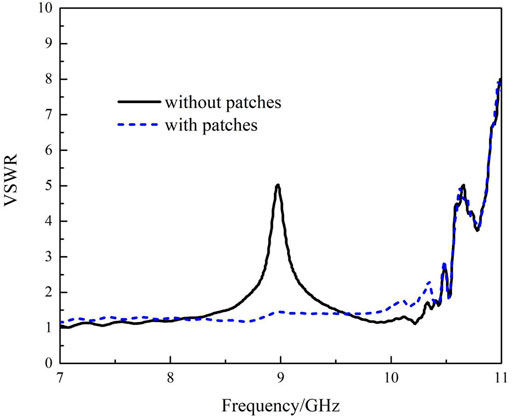
FIGURE 7. VSWR of designs with and without parasitic patches.
The prototype illustrated in the inset of Figure 8 is fabricated on F4B substrate with whole dimensions of
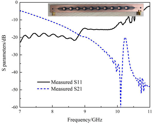
FIGURE 8. Measured S parameters of the proposed design. Inset: Photo of the prototype.
The simulated and measured far-field radiation patterns are shown in Figure 9, corresponding to different frequencies. The broadside radiation appears at 8.9 GHz. The measured results are in good agreement with the simulated results. Within band from 7 to 9 GHz, the design shows radiation of backward frequency scanning. And within band from 9 to 10 GHz, forward radiation is accomplished. the direction of the main lobe at 7 GHz, 8 GHz, 9.5 GHz and 10 GHz are -41°, -17°, 16° and 42°, respectively. The broadside radiation locates at 8.9 GHz with narrowest HPBW of 4.5
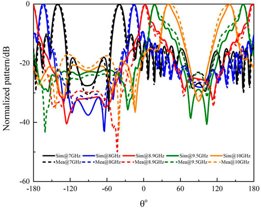
FIGURE 9. Simulated and measured normalized pattern at different frequencies.
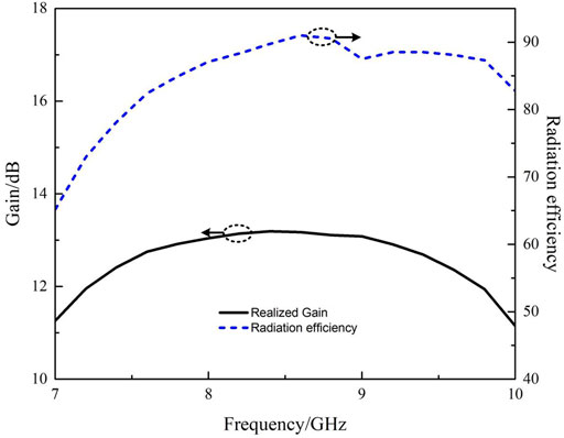
FIGURE 10. Realized gain and radiation efficiency.
Conclusion
In this letter, a high-efficient dual-beam LWA based on complementary SSPP modes has been proposed. Wide scanning coverage from backward radiation to forward radiation is achieved. Additional parasitic patch array is introduced in the modulated composite unit to improve the radiation efficiency and mitigates the OSB effect. The device shows stable gain distribution within the whole operating band, while scanning from −41
Data Availability Statement
The original contributions presented in the study are included in the article/Supplementary Material, further inquiries can be directed to the corresponding author.
Author Contributions
All authors listed have made a substantial, direct, and intellectual contribution to the work and approved it for publication.
Funding
This work is supported by Open Research Program of State Key Laboratory of Millimeter Wave under contract K202221.
Conflict of Interest
The authors declare that the research was conducted in the absence of any commercial or financial relationships that could be construed as a potential conflict of interest.
Publisher’s Note
All claims expressed in this article are solely those of the authors and do not necessarily represent those of their affiliated organizations, or those of the publisher, the editors, and the reviewers. Any product that may be evaluated in this article, or claim that may be made by its manufacturer, is not guaranteed or endorsed by the publisher.
References
1. Jackson DR, Caloz C, Itoh T. Leaky-Wave Antennas. Proc IEEE (2012) 100(7):2194–206. doi:10.1109/jproc.2012.2187410
2. Caloz C, Jackson DR, Itoh T. Leaky-wave Antennas, in Frontiers in AntennasNext Generation Design & Engineering. New York: McGraw-Hill (2011).
3. Ma HF, Shen X, Cheng Q, Jiang WX, Cui TJ. Broadband and High-Efficiency Conversion from Guided Waves to Spoof Surface Plasmon Polaritons. Laser Photon Rev (2014) 8:146–51. doi:10.1002/lpor.201300118
4. Pan BC, Liao Z, Zhao J, Cui TJ. Controlling Rejections of Spoof Surface Plasmon Polaritons Using Metamaterial Particles. Opt Express (2014) 22:13940. doi:10.1364/oe.22.013940
5. Gao X, Hui Shi J, Shen X, Feng Ma H, Xiang Jiang W, Li L, et al. Ultrathin Dual-Band Surface Plasmonic Polariton Waveguide and Frequency Splitter in Microwave Frequencies. Appl Phys Lett (2013) 102:151912. doi:10.1063/1.4802739
6. Panaretos AH, Werner DH. Spoof Plasmon Radiation Using Sinusoidally Modulated Corrugated Reactance Surfaces. Opt Express (2016) 24:2443. doi:10.1364/oe.24.002443
7. Xu Y, Gu C, Hou B, Lai Y, Li J, Chen H. Broadband Asymmetric Waveguiding of Light without Polarization Limitations. Nat Commun (2013) 4:2561. doi:10.1038/ncomms3561
8. Xu K-D, Lu S, Guo Y-J, Chen Q. High-order Mode of Spoof Surface Plasmon Polaritons and its Application in Bandpass Filters. IEEE Trans Plasma Sci (2021) 49(1):269–75. doi:10.1109/tps.2020.3043889
9. Zhang Q, Zhang Q, Chen Y. Spoof Surface Plasmon Polariton Leaky-Wave Antennas Using Periodically Loaded Patches above PEC and AMC Ground Planes. Antennas Wirel Propag Lett (2017) 16:3014–7. doi:10.1109/lawp.2017.2758368
10. Liu L, Chen M, Cai J, Yin X, Zhu L. Single-Beam Leaky-Wave Antenna with Lateral Continuous Scanning Functionality Based on Spoof Surface Plasmon Transmission Line. IEEE Access (2019) 7:25225–31. doi:10.1109/access.2019.2899824
11. Cao D, Li Y, Wang J. Spoof Surface Plasmon Polaritons Fed Frequency-Scanning Open-Loop Antenna Arrays. IEEE Access (2019) 7:179954–60. doi:10.1109/access.2019.2956999
12. Ye L, Yang Z, Zhuo J, Han F, Li W, Liu QH. A Back-Fire to Forward Wide-Angle Beam Steering Leaky-Wave Antenna Based on SSPPs. in IEEE Trans Antennas Propagation (2021) 1:1. doi:10.1109/TAP.2021.3137241
13. Yu HW, Jiao YC, Zhang C, Weng ZB. Dual-Linearly Polarized Leaky-Wave Patch Array with Low Cross-Polarization Levels Using Symmetrical Spoof Surface Plasmon Polariton Lines. IEEE Trans Antennas Propagation (2021) 69(3):1781–6.
14. Wei D, Li J, Yang J, Qi Y, Yang G. Wide-Scanning-Angle Leaky-Wave Array Antenna Based on Microstrip SSPPs-TL. Antennas Wirel Propag Lett (2018) 17(8):1566–70. doi:10.1109/lawp.2018.2855178
15. Ge S, Zhang Q, ChiuChiu CYY, Chen Y, Murch RD. Single-Side-Scanning Surface Waveguide Leaky-Wave Antenna Using Spoof Surface Plasmon Excitation. IEEE Access (2018) 6:66020–9. doi:10.1109/access.2018.2879086
16. Du X, Ren J, Li H, Zhang C, Liu Y, Yin Y. Design of a Leaky-Wave Antenna Featuring Beam Scanning from Backfire Utilizing Odd-Mode Spoof Surface Plasmon Polaritons. IEEE Trans Antennas Propagat (2021) 69(10):6971–6. doi:10.1109/tap.2021.3076166
Keywords: dual-beam, frequency scanning, SSPPs, highly efficient, parasitic patch array
Citation: Pan BC, Guo BJ, Yu P, Cai BG, Dai XW and Luo GQ (2022) Highly Efficient Dual-Beam Frequency Scanning Based on SSPPs With Parasitic Patch Array. Front. Phys. 10:851121. doi: 10.3389/fphy.2022.851121
Received: 09 January 2022; Accepted: 24 January 2022;
Published: 17 February 2022.
Edited by:
Zhewang Ma, Saitama University, JapanReviewed by:
Xi Gao, Guangxi University of Science and Technology, ChinaShen Xiaopeng, China University of Mining and Technology, China
Copyright © 2022 Pan, Guo, Yu, Cai, Dai and Luo. This is an open-access article distributed under the terms of the Creative Commons Attribution License (CC BY). The use, distribution or reproduction in other forums is permitted, provided the original author(s) and the copyright owner(s) are credited and that the original publication in this journal is cited, in accordance with accepted academic practice. No use, distribution or reproduction is permitted which does not comply with these terms.
*Correspondence: Guo Qing Luo, luoguoqing@hdu.edu.cn