 Jiangpeng Wang
 Jingjing Zhang1,2
 Hao Gao
 Xiaojian Fu
 Di Bao
 Tie Jun Cui
95% of researchers rate our articles as excellent or good
Learn more about the work of our research integrity team to safeguard the quality of each article we publish.
Find out more
ORIGINAL RESEARCH article
Front. Phys. , 22 March 2022
Sec. Optics and Photonics
Volume 10 - 2022 | https://doi.org/10.3389/fphy.2022.850186
This article is part of the Research Topic Plasmonic Metamaterials and Electromagnetic Devices View all 20 articles
Spoof localized surface plasmons (LSPs) have proven significant advantages in sensing and detection. In this work, we propose a high-Q-factor and high-sensitivity hybridized spoof LSP sensor and a mixed-resolution algorithm. The sensor consists of two concentric inner and outer LSP structures with corrugated rings coupled to each other. The achieved Q-factor is up to 178, and the sensing figure of merit (FoM) is up to 30. Moreover, a mixed-resolution algorithm, combined with multiple resonant peaks, is proposed to enhance the Q-factor and sensing FoM. This algorithm doubles the Q-factor and sensing FoM effectively. This mixed-resolution sensor has a wide range of application prospects in the field of high-frequency on-chip resonators and sensors.
Spoof localized surface plasmons (LSPs) in corrugated metal cylinders were proposed by Pendry et al. [1] in 2012, and magnetic spoof LSPs with long curved corrugated grooves were proposed and experimentally demonstrated by Cui et al. [2]. In 2014, Cui et al. realized the design and verification of ultrathin LSPs for the first time [3]. Following that, many different structures of spoof LSPs such as ultrathin corrugated metal–insulator–metal ring resonator [4], compact spoof LSPs [5], spoof LSP hybridization [6], spiral spoof LSPs [7], and meander line structure [8] were investigated and proposed. Spoof LSPs have been proven to be valuable in the design of resonators [9–11], filters [12, 13], sensors [14], biomedical applications [15], etc. Due to the strong confinement of the electromagnetic field [16], the spoof LSP resonance has a high-Q-factor [17] and is sensitive to the surrounding environment. Therefore, spoof LSP structures became popular and widely used in microwave and millimeter wave sensor research.
A metallic ring with corrugated gratings is the elementary structure of spoof LSPs. There have been several reports on spoof LSP sensors, such as quarter-mode spoof LSP microfluidic chemical sensor [18, 19], flexible and printed microwave plasmonic sensor [20], single hybrid plasmonic resonator [21], and effective LSP sensor [22]. Those spoof LSP structures could improve Q-factor and sensitivity significantly, compared to conventional resonator structures [21, 23]. Asymmetric metamaterials [24] or symmetry-broken in toroidal plasmonic resonator [25] can exhibit sharp Fano-resonances or a high-Q trapped mode, which shows excellent performance in resonator and sensor fields. In previous research, hybridization of spoof LSP structures can produce enormous field enhancement and improve the Q-factor [26]. The hybridized spoof LSPs can enhance resonance while preserving the structure area, which is beneficial to on-chip integration design [6].
In addition to simple physical sensors, other dimensions of sensing enhancing methods such as multifactor sensing [27], chemical sensing with the addition of black phosphorus and graphene [28], and index sensors with multimode interference [29] have been carried out. Nevertheless, those methods are limited to the structural level, resulting in high operation difficulty and cost. It would be cheap, convenient, fast, and easy to implement Q-factor and sensing FoM enhancement through back-end data processing.
In this study, we designed a multimode and high-sensitivity sensor in the microwave region, and this sensor is based on hybridized spoof localized surface plasmons and proposes a mixed-resolution algorithm to enhance the Q-factor further. The hybridized spoof LSP sensor is a coupling structure with inner and outer corrugated rings. The sensor exhibits a high-Q-factor and high sensing FoM with samples of different permittivity values on the top of the spoof LSP structure. Measurements and simulations match well, which confirm the theory. It also demonstrated that spoof LSPs could be excited and functional as a microwave sensor with a high-Q-factor and sensing FoM. The proposed mixed-resolution algorithm combines two or more resonant peaks to form one resonant peak with almost doubled Q-factor and sensing FoM than raw data. The mixed-resolution spoof LSP sensor can be extended to the terahertz band and has a wide range of applications in on-chip high-frequency resonators and sensors.
The proposed high-Q concentric corrugated ring-coupled resonator is excited by microstrip lines (MSs), as demonstrated in Figure 1. Both the inner and outer LSP structures contain 24 grooves. The inner radius, the groove height, the groove width, and the strip width of the inner and the outer corrugated rings are
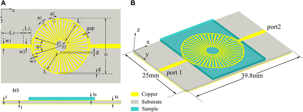
FIGURE 1. Proposed spoof LSP sensor structure. (A) The detail and geometric parameters of the top view. (B) The 3D perspective view of the spoof LSP sensor. (C) The side view of the schematic diagram.
The simulated transmission coefficients of the spoof localized surface plasmon resonator are obtained using the commercial software CST. The experimental results are measured using a vector network analyzer (Agilent N5230C). Both simulated and measured results are plotted in Figure 2A. It shows that the simulated results are in good agreement with the measured results. This structure is designed with 7 resonance peaks, marked as m1 to m7 from the range of 0 to 8 GHz. Those resonance frequencies are located at 2.03, 3.72, 4.29, 4.91, 5.69, 6.46, and 7.82 GHz. In the measurement, the measured frequency responses confirmed those 7 resonance peaks. And those frequency points are located at 2.037, 3.736, 4.27, 4.94, 5.73, 6.43 and 7.77 GHz, respectively, which matches the design. The quality factor of resonator represents the ratio of stored energy to the consumed energy of the resonant circuit, respectively, which can be expressed as follows:
where
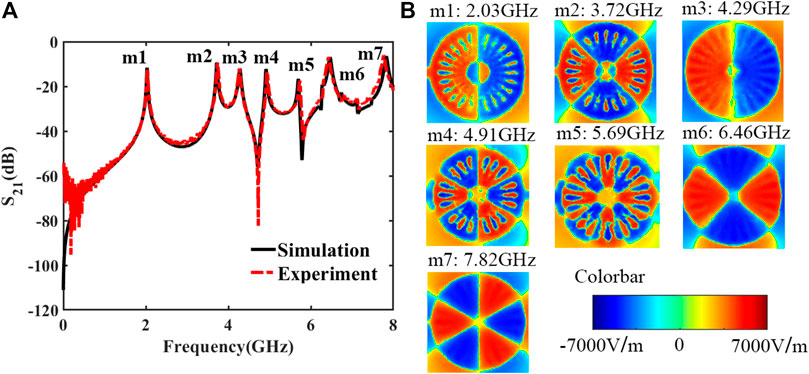
FIGURE 2. (A) Simulated and measured transmission coefficients of the spoof LSP resonator. (B) The simulated 2D near electric field distributions at the resonance frequencies on the plane 1 mm above the resonator.
To further study the mechanism of this high-Q-factor resonance of the spoof LSP structure, a 2D near-field electric distribution at the resonance modes
Previous studies have shown that the Q-factor of outer corrugated spoof LSP resonator is higher than that of inner LSP resonator [5, 30], so only the outer corrugated spoof LSPs are analyzed here. The transmission coefficients of the hybridized spoof LSP resonator and outer corrugated spoof LSP resonators covered with tested samples are compared and analyzed to verify the superiority of the hybridized structure in the sensing test. In this part, only odd modes
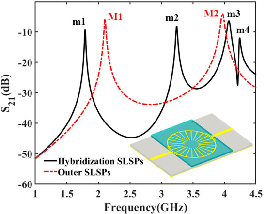
FIGURE 3. Transmission coefficients of the hybridization spoof LSP resonator and outer corrugated spoof LSP resonator. The inset shows the outer corrugated spoof LSP structure.
The hybridized spoof LSP structure-based resonator with a high-Q-factor is a primary condition for the resonance sensor as the sensitivity requirement. In order to verify the sensing performance, a prototype of this LSP sensor and several samples with different permittivities are fabricated and characterized for demonstration. A spoof LSP sensor and excitation microstrip lines are printed on the substrate of Rogers RT5880, with a relative permittivity of 2.2, as shown in Figure 4. Three Rogers materials, namely, RT5880, RO3003, and RO4003, are applied in the test samples. Those samples are 0.508 mm thickness, and their relative permittivity is 2.2, 3, and 3.55, respectively. The samples are kept in the same size, while their permittivities are different. Those sizes are 20 mm × 25 mm×0.508 mm, and they can be laid on the spoof LSP sensor.
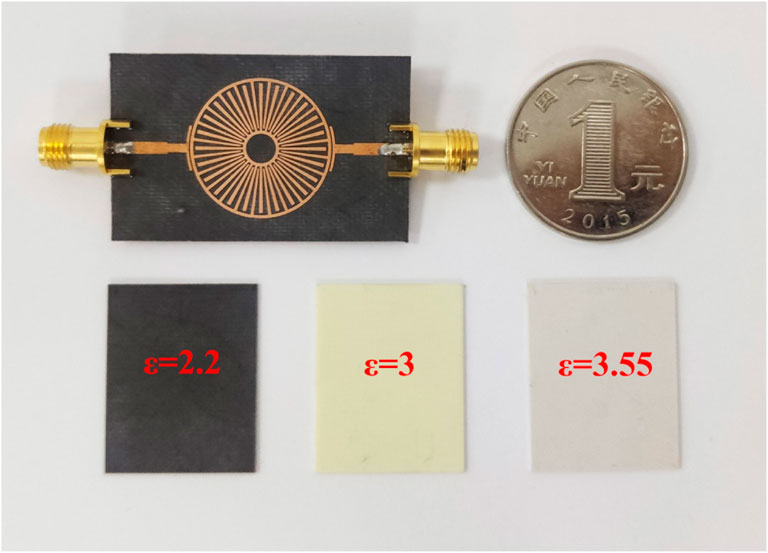
FIGURE 4. Photo of the fabricated prototype. The three small squares at the bottom of the picture are the three samples under assessment with different permittivities for sensor detection.
Sensing FoM is an important parameter to characterize the sensor’s sensitivity [31], which synthetically indicates the overall interaction effect with the environment. The sensing FoM is defined as follows [32]:
where sensitivity is the frequency offset
where the refractive index n means the square root of the relative permittivity
The sample under test is placed directly above the spoof LSP structure in the measurement. The sample and the sensor are fixed together with two identical small iron clips to secure the position and distance, as illustrated in Figure 5A. The spoof LSPs have strong confinement of electromagnetic field, and the field intensity outside of spoof LSPs is weak. Therefore, the small iron clip has little impact on the sensor’s performance, which is also verified in the measurement process. The sensor’s simulated and measured transmission coefficients are plotted in Figure 5A. Figures 5B,C show the detail of the m5’s resonant mode in simulation and in the measurement.
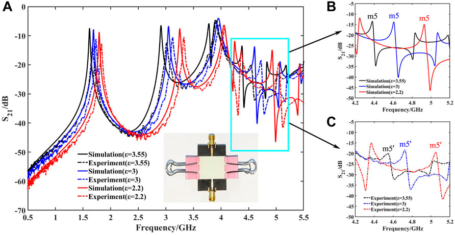
FIGURE 5. (A) Simulated and measured transmission coefficients of the spoof LSP sensor. The inset is a photograph of the sensor under experiment. (B) Details of simulated transmission coefficients of resonant mode
The simulated odd dipole modes locate at 1.6176, 1.6896, and 1.792 GHz with Q-factors of 95.2, 94.5, and 102 when the sample relative permittivity changes from 3.55, 3, to 2.2. The odd quadrupole modes are located at 2.912, 3.0496, and 3.2544 GHz with Q-factors of 112, 116.8, and 124.6 when the sample relative permittivity changes from 3.55, 3, to 2.2. Meanwhile, the odd octupole mode
The measured results are presented in Figures 5A,C as the dotted line. The measured odd dipole modes locate at 1.6738, 1.724, and 1.835 GHz with Q-factors of 59.8, 76.7, and 81.6 when the sample relative permittivity changes from 3.55 to 3 to 2.2. The odd quadrupole modes locate at 3.015, 3.113, and 3.325 GHz with Q-factors of 70.8, 94.1, and 106.3, while the odd octupole mode locates at 4.546, 4.711, and 5.049 GHz with Q-factors of 44.6, 103, and 111. When the permittivity
Comparing the simulated results with measured results, it can conclude that the frequencies of the resonant modes are blue-shifted, and both the Q-factor and sensing FoM have been reduced, especially in the odd octuple mode. This shift could be caused by the unavoidable air gap between the samples and the sensor. Also, from the simulation and experiment, it is not difficult to find that the lower the permittivity of the sample, the higher the resonant frequency. The air gap causes the effective permittivity above the sensor to be less than the relative permittivity of the samples, resulting in this blue shift. The odd octuple mode is a resonant mode which is similar to Fano resonance produced by coupling internal and external resonators, requiring higher environment configuration. Manufacturing, material, and measurement errors affect the measured resonant frequency, resonant intensity, and sensitivity.
The proposed hybridized spoof LSP sensor shows excellent performance in simulation and measurement, with Q-factors up to 178.4 and sensing FoM up to 30.72
Although the proposed hybridized sensor achieved a very high-Q-factor and sensing FoM, they are expected to be even higher by data processing. Therefore, a mixed-resolution optimization algorithm is proposed to enhance the Q-factor and sensing FoM based on the multi-resonance property. The algorithm is based on the resulting linear data and combines several resonant modes later to form a new resonant mode. The new resonant mode achieves narrower 3dB bandwidth, improving the Q-factor and sensing FoM.
To precisely describe the algorithm for increasing the resonant Q-factor and sensing FoM, a schematic diagram is inserted in Figure 6. Suppose there is a resonant peak, which consists of a curve
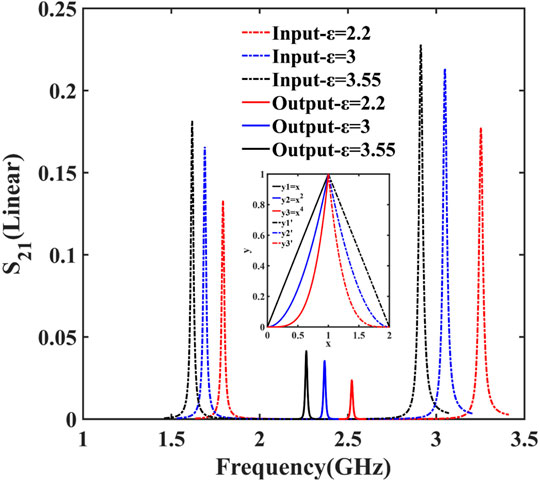
FIGURE 6. Input and output linear transmission coefficients of the mixed-resolution algorithm.
First, to apply this mixed-resolution algorithm to sensor data processing, 100 linear sampling points at higher frequency and 100 at lower frequency around the dipole and quadrupole resonant frequencies were taken, respectively. The sampling points with different permittivities are shown as the input dotted curves in Figure 6. Then, these three groups of data are processed using the described mixed-resolution algorithm, respectively, and it generated three new groups of resonant peaks, as shown in the solid line in Figure 6. The frequency of the output resonant peak is half the sum of the corresponding frequencies of the dipole and quadrupole. Finally, according to Eqs 1–3, an algorithm for automatically calculating resonant Q-factors and sensing FoM is developed. The calculated input and output Q-factor and sensing FoM are listed in Table 1. As compared in Table 1, the mixed-resolution algorithm increases the Q-factor from 96 by 1.93 times to 185.1, and the sensing FoM increases by 2.17 times, from 23.38 to 50.7. The algorithm can almost double the Q-factor and sensing FoM without changing the sensor structure, which is an important breakthrough in the microwave sensor field [34–37]. With this mixed-resolution algorithm, sensors are expected to achieve multimode enhanced sensing in the future. Also, it can detect more subtle environmental changes to a great extent.
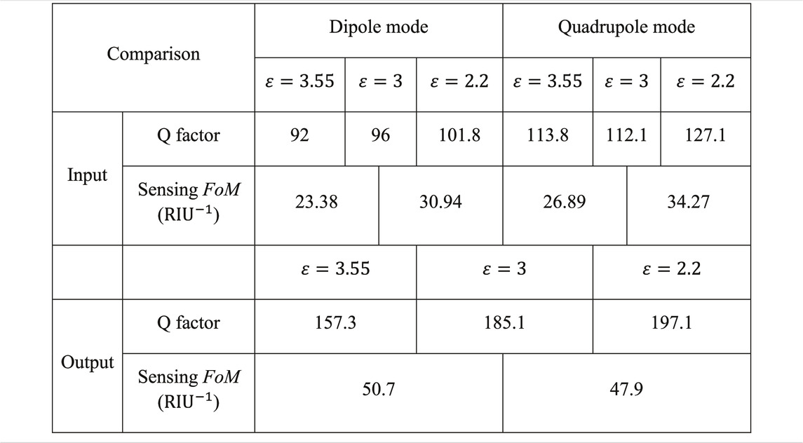
TABLE 1. Comparison of input and output Q-factor and sensing FoM. All of the data in the table are calculated automatically using the mixed-resolution algorithm.
In this work, a hybridized spoof LSP sensor is proposed, implemented, and measured with high environmental sensitivity. A mixed-resolution algorithm was also proposed to further improve the Q-factor and sensing FoM by combining multimode resonant peaks. A prototype was designed, fabricated, and measured for demonstration. High-Q-factor and high sensing FoM are achieved by applying the algorithm. Meanwhile, the mixed-resolution can further double them. The hybridized spoof LSP sensor and the mixed-resolution algorithm have great potential in the field of high-frequency on-chip resonators and sensors.
The original contributions presented in the study are included in the article/Supplementary Material, further inquiries can be directed to the corresponding authors.
JW conducted the numerical simulations and experiment, and wrote the manuscript. DB and TC conceived the idea, suggested the designs, and supervised the work. All the authors conducted the analytical modeling and discussed the results. XF provided some assistance in the experimental process.
This work was supported in part from the National Key Research and Development Program of China (Grant Nos. 2017YFA0700201, 2017YFA0700202, and 2017YFA0700203), the National Natural Science Foundation of China (Grant No. 61735010), and the 111 Project (Grant No. 111-2-05).
HG was employed by the company Silicon Austria Labs GmbH.
The remaining authors declare that the research was conducted in the absence of any commercial or financial relationships that could be construed as a potential conflict of interest.
All claims expressed in this article are solely those of the authors and do not necessarily represent those of their affiliated organizations, or those of the publisher, the editors, and the reviewers. Any product that may be evaluated in this article, or claim that may be made by its manufacturer, is not guaranteed or endorsed by the publisher.
1. Pors A, Moreno E, Martin-Moreno L, Pendry JB, Garcia-Vidal FJ. Localized Spoof Plasmons Arise while Texturing Closed Surfaces. Phys Rev Lett (2012) 108(22):223905. doi:10.1103/physrevlett.108.223905
2. Huidobro PA, Shen X, Cuerda J, Moreno E, Martin-Moreno L, Garcia-Vidal FJ, et al. .Magnetic Localized Surface Plasmons. Phys Rev X (2014) 4:101103. doi:10.1103/physrevx.4.021003
3. Shen X, Cui TJ. Ultrathin Plasmonic Metamaterial for Spoof Localized Surface Plasmons. Laser Photon Rev (2014) 8(1):137–45. doi:10.1002/lpor.201300144
4. Zhou YJ, Xiao QX, Jia Yang B. Spoof Localized Surface Plasmons on Ultrathin Textured MIM Ring Resonator with Enhanced Resonances. Sci Rep (2015) 5:14819. doi:10.1038/srep14819
5. Bao D, Rajab KZ, Jiang WX, Cheng Q, Liao Z, Cui TJ. Experimental Demonstration of Compact Spoof Localized Surface Plasmons. Opt Lett (2016) 41(23):5418–21. doi:10.1364/ol.41.005418
6. Bao D, Cheng Q, Jiang WX, Zhang JJ, Liao Z, Wu JW, et al. .Concentric Designer Plasmon Hybridization in Deep Subwavelength Metamaterial Resonator. Appl Phys Lett (2019) 115. 1063.doi:10.1063/1.5116776
7. Gao Z, Gao F, Zhang Y, Zhang B. Complementary Structure for Designer Localized Surface Plasmons. Appl Phys Lett (2015) 107:191103. doi:10.1063/1.4935360
8. Zhao P-C, Zong Z-Y, Wu W, Li B, Fang D-G. An FSS Structure with Geometrically Separable Meander-Line Inductors and Parallel-Plate Capacitors. IEEE Trans Antennas Propagat (2017) 1:1. doi:10.1109/tap.2017.2729158
9. Yang BJ, Zhou YJ, Xiao QX. Spoof Localized Surface Plasmons in Corrugated Ring Structures Excited by Microstrip Line. Opt Express (2015) 23(16):21434–42. doi:10.1364/oe.23.021434
10. Zhang X, Cui TJ. Single-Particle Dichroism Using Orbital Angular Momentum in a Microwave Plasmonic Resonator. ACS Photon (2020) 7(12):3291–7. doi:10.1021/acsphotonics.0c01139
11. Li Z, Liu L, Gu C, Ning P, Xu B, Niu Z, et al. .Multi-band Localized Spoof Plasmons with Texturing Closed Surfaces. Appl Phys Lett (2014) 104:101063. doi:10.1063/1.4868126
12. Shen Y, Chen N, Dong G, Hu S. Manipulating Multipole Resonances in Spoof Localized Surface Plasmons for Wideband Filtering. Opt Lett (2021) 46:1364. doi:10.1364/ol.417004
13. Yang Z-B, Guan D-F, Huang X, Zhang HC, You P, Xu S-D, et al. .Compact and Wideband Octuple-Mode Filter Based on Hybrid Substrate Integrated Waveguide and Spoof Localized Surface Plasmon Structure. IEEE Trans Circuits Syst (2020) 67(11):2377–81. doi:10.1109/tcsii.2020.2971235
14. Zhao HZ, Zhou YJ, Cai J, Li QY, Li Z, Xiao ZY. Ultra-high Resolution Sensing of Glucose Concentration Based on Amplified Half-Integer Localized Surface Plasmons Mode. J Phys D: Appl Phys (2020) 53:1088. doi:10.1088/1361-6463/ab5b4f
15. Anker JN, Hall WP, Lyandres O, Shah NC, Zhao J, Van Duyne RP. Biosensing with Plasmonic Nanosensors. Nat Mater (2008) 7(6):442–53. doi:10.1038/nmat2162
16. Shen X, Cui TJ, Martin-Cano D, Garcia-Vidal FJ. Conformal Surface Plasmons Propagating on Ultrathin and Flexible Films. Proc Natl Acad Sci (2013) 110(1):40–5. doi:10.1073/pnas.1210417110
17. Chen L, Xu N, Singh L, Cui T, Singh R, Zhu Y, et al. .Defect-Induced Fano Resonances in Corrugated Plasmonic Metamaterials. Adv Opt Mater (2017) 5:1600960. doi:10.1002/adom.201600960
18. Shao RL, Zhou YJ, Yang L. Quarter-mode Spoof Plasmonic Resonator for a Microfluidic Chemical Sensor. Appl Opt (2018) 57(28):8472–7. doi:10.1364/ao.57.008472
19. Gholamian M, Shabanpour J, Cheldavi A. Highly Sensitive Quarter-Mode Spoof Localized Plasmonic Resonator for Dual-Detection RF Microfluidic Chemical Sensor. J Phys D-Applied Phys (2020) 53:145401. doi:10.1088/1361-6463/ab667
20. Dai LH, Zhao HZ, Zhao X, Zhou YJ. Flexible and Printed Microwave Plasmonic Sensor for Noninvasive Measurement. IEEE Access (2020) 1:1. doi:10.1109/access.2020.3020268
21. Zhang X, Yan RT, Cui TJ. High-FoM Resonance in Single Hybrid Plasmonic Resonator via Electromagnetic Modal Interference. IEEE Trans Antennas Propagat (2020) 68(8):6447–51. doi:10.1109/tap.2020.2970037
22. Jiang Q, Yu Y, Zhao Y, Zhang Y, Liu L, Li Z. Ultra-Compact Effective Localized Surface Plasmonic Sensor for Permittivity Measurement of Aqueous Ethanol Solution with High Sensitivity. IEEE Trans Instrumentation Meas (2021) 70:1109. doi:10.1109/tim.2021.3092783
23. Xiao QX, Yang BJ, Zhou YJ. Spoof Localized Surface Plasmons and Fano Resonances Excited by Flared Slot Line. J Appl Phys (2015) 118:1063. doi:10.1063/1.4938153
24. Wu C, Khanikaev AB, Adato R, Arju N, Yanik AA, Altug H, et al. .Fano-resonant Asymmetric Metamaterials for Ultrasensitive Spectroscopy and Identification of Molecular Monolayers. Nat Mater (2011) 11(1):69–75. doi:10.1038/nmat3161
25. Zhang X, Cui TJ. Deep-Subwavelength and High-Q Trapped Deep-Subwavelength and High-Q Trapped Mode Induced by Symmetry-Broken in Toroidal Plasmonic Resonator. IEEE Trans Antennas Propagat (2021) 69(4):2122–9. doi:10.1109/tap.2020.3026480
26. Zhang J, Liao Z, Luo Y, Shen X, Maier SA, Cui TJ. Spoof Plasmon Hybridization. Laser Photon Rev (2017) 11:1003. doi:10.1002/lpor.201600191
27. Sun X, Du H, Dong X, Hu Y, Duan Ja. Simultaneous Curvature and Temperature Sensing Based on a Novel Mach-Zehnder Interferometer. Photonic Sens (2019) 10(2):171–80. doi:10.1007/s13320-019-0551-z
28. Singh Y, Paswan MK, Raghuwanshi SK. Sensitivity Enhancement of SPR Sensor with the Black Phosphorus and Graphene with Bi-layer of Gold for Chemical Sensing. Plasmonics (2021) 10:11468. doi:10.1007/s11468-020-01315-3
29. Taue S, Daitoh H, Fukano H. Sensitivity Enhancement of Fiber-Optic Refractive index Sensor Based on Multimode Interference with Gold Nanoparticles. Jpn J Appl Phys (2015) 54:04DL07. doi:10.7567/jjap.54.04dl07
30. Zhou YJ, Dai LH, Li QY, Xiao ZY. Two-Way Fano Resonance Switch in Plasmonic Metamaterials. Front Phys (2020) 8:3389. doi:10.3389/fphy.2020.576419
31. Zhang X, Cui WY, Lei Y, Zheng X, Zhang J, Cui TJ. Spoof Localized Surface Plasmons for Sensing Applications. Adv Mater Tech (2021) 6.
32. Offermans P, Schaafsma MC, Rodriguez SRK, Zhang Y, Crego-Calama M, Brongersma SH, et al. .Universal Scaling of the Figure of Merit of Plasmonic Sensors. Acs Nano (2011) 5(6):5151–7. doi:10.1021/nn201227b
33. Homola J, Yee SS, Gauglitz G. Surface Plasmon Resonance Sensors: Review. Sensors and Actuators B-Chemical (1999) 54(1-2):3–15. doi:10.1016/s0925-4005(98)00321-9
34. Monzón-Hernández D, Martínez-Ríos A, Salceda-Delgado G, Villatoro J. Compact Sensors Based on Cascaded Single-Mode–Multimode–Single-Mode Fiber Structures. Appl Phys Express (2013) 6.
35. Rota-Rodrigo S, Gonzalez-Herraez M, Lopez-Amo M. Compound Lasing Fiber Optic Ring Resonators for Sensor Sensitivity Enhancement. J Lightwave Technol (2015) 33(12):2690–6. doi:10.1109/jlt.2014.2387428
36. Chen Z, Yang J, Zhang X, Bai J, Feng T, Tang J, et al. .Mathematical Model and Reference Frequency Optimization for Digital Dual-Band Pulsewidth Modulation. In 2020 IEEE MTT-S International Wireless Symposium (IWS) (2020). p. 1–3.
Keywords: spoof localized surface plasmons, sensor, hybridization, mixed-resolution, spoof surface plasmons
Citation: Wang J, Zhang J, Gao H, Fu X, Bao D and Cui TJ (2022) Mixed-Resolution High-Q Sensor Based on Hybridized Spoof Localized Surface Plasmons. Front. Phys. 10:850186. doi: 10.3389/fphy.2022.850186
Received: 07 January 2022; Accepted: 11 February 2022;
Published: 22 March 2022.
Edited by:
Kai-Da Xu, Xi’an Jiaotong University, ChinaReviewed by:
Zhen Liao, Hangzhou Dianzi University, ChinaCopyright © 2022 Wang, Zhang, Gao, Fu, Bao and Cui. This is an open-access article distributed under the terms of the Creative Commons Attribution License (CC BY). The use, distribution or reproduction in other forums is permitted, provided the original author(s) and the copyright owner(s) are credited and that the original publication in this journal is cited, in accordance with accepted academic practice. No use, distribution or reproduction is permitted which does not comply with these terms.
*Correspondence: Di Bao, ZGliYW9Ac2V1LmVkdS5jbg==; Tie Jun Cui, dGpjdWlAc2V1LmVkdS5jbg==
Disclaimer: All claims expressed in this article are solely those of the authors and do not necessarily represent those of their affiliated organizations, or those of the publisher, the editors and the reviewers. Any product that may be evaluated in this article or claim that may be made by its manufacturer is not guaranteed or endorsed by the publisher.
Research integrity at Frontiers
Learn more about the work of our research integrity team to safeguard the quality of each article we publish.