- School of Physics and State Key Laboratory of Optoelectronic Materials and Technologies, Sun Yat-Sen University, Guangzhou, China
The topology of isofrequency surface governs the electromagnetic wave propagation and light–matter interaction in metamaterials. For most metamaterials with local medium description, the low-frequency isosurfaces are typical spheres or ellipsoids centered at zero momentum, which, to some extent, limits our manipulation ability on low-frequency wave. In this work, based on connection-type wire metamaterials, we propose a scheme to engineer the shapes of isofrequency surfaces. An equivalent circuit model is developed to analyze the low-frequency dispersion of connection-type metamaterials. It implies that the shape of index ellipsoids at quasistatic limit is determined by the equivalent inductances and capacitances of the metallic meshes. By adjusting these equivalent circuit parameters, we can achieve the isotropic or anisotropic index ellipsoids at quasistatic limit and, hence, a cruciform or bowtie-shaped isofrequency contours for the lowest-frequency band. Our results demonstrate a feasible platform for topological engineering of isofrequency surfaces, which may pave the way to novel devices for manipulating long-wavelength electromagnetic wave.
1 Introduction
The isofrequency surfaces (IFSs) of a medium play an important role in determining the electromagnetic (EM) wave propagation[1] and light–matter interactions [2, 3] inside the medium. For a natural material, the shape of IFSs depends on its microscopic atomic arrangement and is usually an isotropic sphere or an anisotropic ellipsoid in k space. Metamaterials (MMs) [4–10], artificially synthesized materials with subwavelength microstructures, can exhibit various types of closed/open IFSs with exotic topologies (concave sphere [11, 12], hyperboloid [2, 3, 13, 14], cuboid [15, 16], etc.), which lead to anomalous wave phenomena (negative refraction [1, 11, 12], subwavelength imaging [17–20], self-collimation [15, 16, 21, 22], etc.) alongside numerous engineering applications. However, since their unnatural responses rely on the EM resonance of metallic structures [4, 5, 10], these exotic IFSs and associated phenomena only occur near the resonant frequency, which limits their working bandwidth. Also, when the wave frequency approaches quasistatic limit, the IFSs of these artificial media usually deteriorate to an ordinary ellipsoid centered at a zero k-point.
It would be highly desirable if the shapes of low-frequency IFSs can be customized at will, then we could control the EM wave propagation behavior in a relatively broader bandwidth. It is well known that metallic wire medium [4, 23–40], such as disconnected wire arrays, can exhibit the strong spatial dispersion (nonlocal effect) even in long-wavelength limit [25, 26]. By incorporating two or more sets of metallic meshes, one can engineer the density of states at quasistatic limit [28, 32, 33]. The EM properties of these multiple interlocking meshes are governed by electric circuit equations [28, 29] rather than Maxwell equations [41]; they are, thus, called non-Maxwellian medium. Interestingly, researchers [33] found that the global connectivity of these metallic meshes can introduce a momentum shift of the low-frequency index ellipsoid away from the zero k-point. Recently, wire medium again attracted the attention of researchers, since it could serve as a new design degree of freedom to tailor the low-frequency dispersion [34–37] and associated wave properties [38–40] of MMs.
In this study, based on connection-type MMs [28, 32–34, 36] that support multiple quasistatic modes at a nonzero k-point, we propose a scheme to engineer the shapes of low-frequency IFSs. As frequency increases from zero, isotropic or anisotropic index ellipsoids emerge from these nonzero k-points. By properly shaping the index ellipsoids, one can, in principle, realize arbitrary-shaped isofrequency contours (IFCs) even for the lowest frequency band. The benefit of our method is that it may provide a novel way for manipulating long-wavelength EM wave. To illustrate our idea clearly, we focus on a 2D slab of connection-type MMs, instead of complex 3D MMs. We develop an equivalent circuit model for the connection-type MMs to describe their low-frequency EM behaviors. The model implies that the shape of index ellipsoids can be engineered via the equivalent inductances and capacitances of the metallic meshes, which are determined by the structural details of the meshes. By appropriately adjusting the metallic structure, we can achieve isotropic or anisotropic index ellipsoids with different group velocities, which agree well with our equivalent circuit model.
2 Results
Connection-type MMs are a type of MMs composed of N sets of interpenetrating metallic meshes, which support (N−1) quasistatic modes lying at a nonzero k-point. Their positions in k space are determined by the global connectivity of the meshes, rather than the structural detail of the meshes. For instance, 2D double-mesh MMs with square lattice [33] can support one quasistatic mode at the Brillouin zone corner (M point), as shown in Figure 1. In addition, this quasistatic mode is not an isolated solution at zero frequency. When frequency increases, the index ellipsoids turn into a circle or ellipse from an isolated point at M, which corresponds to a linear cone dispersion emerging from the M point. While the emerging point can be controlled by designing the mesh connectivity, the shapes of index ellipsoids or the group velocities of linear bands are determined by the structural details. Once we can engineer both the centers and the shapes of the low-frequency index ellipsoids, arbitrary-shaped IFCs can be achieved in principle. For the case in Figure 1, if the index ellipsoids emerging from the M point are a circle, then cruciform-shaped IFCs (dashed line in Figure 1A) would be expected for the midband frequency of band 1. Also, if the index ellipsoids emerging from the M point are an ellipse, bowtie-shaped IFCs (dashed line in Figure 1B) would be expected. Generally speaking, multiple zero-frequency modes would appear at multiple k-points when considering more sets of interlaced wire meshes. By engineering the shape of each ellipse via the equivalent inductances and capacitances between multiple meshes, arbitrary-shaped IFCs can, in principle, be realized in connection-type MMs.
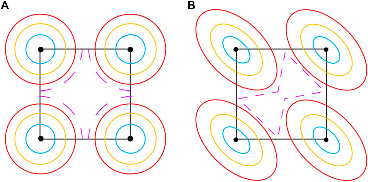
FIGURE 1. Topological engineering of IFCs utilizing the degree of freedom of index ellipsoids at a nonzero k-point. While the centers of index ellipsoids are determined by the global connectivity of the metallic mesh, the shapes of index ellipsoids can be designed via the structural details of the mesh. (A) IFCs of the metamaterial with an isotropic index circle at the Brillouin zone corner. As the frequency increases, the four circles grow and shape into a cruciform. (B) IFCs of the MM with an anisotropic index ellipse at the Brillouin zone corner. As the frequency increases, the four ellipses grow and shape into a bowtie.
To analyze the low-frequency index ellipsoids, we establish an equivalent circuit model which could serve as a guideline in designing connection-type MMs. Here, we consider a 2D double mesh arranged in a square lattice. Centered in its unit cell is a metallic block (height d and width w), whose top (bottom) end is connected to the adjacent unit cell via the metallic bar in the
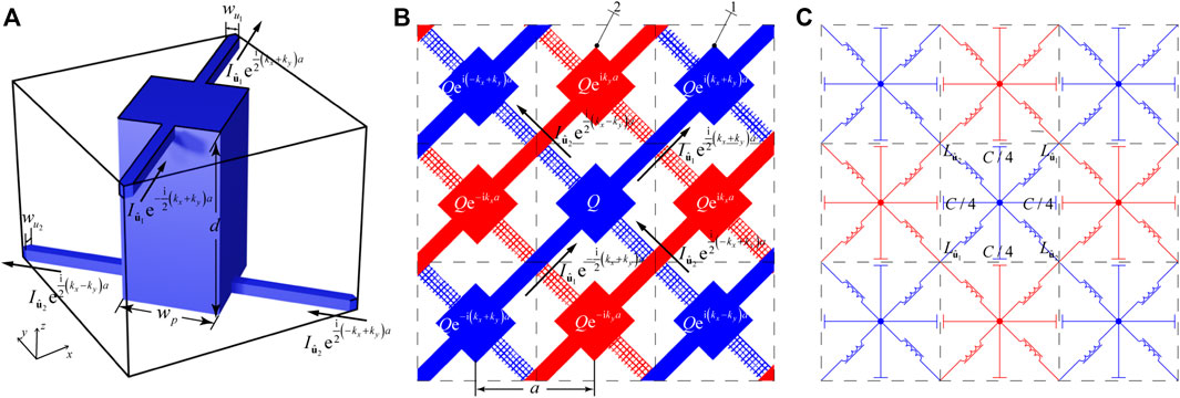
FIGURE 2. 2D double-mesh MM. (A) Unit cell (lattice constant a = 1 cm). The metallic block (width w and height d) centered at the unit cell is connected to the adjacent blocks by two metallic wires (width
We construct a circuit model for this structure to describe its Bloch modes at relatively low (but not zero) frequency. Note that the double-mesh MMs are a slab with finite thickness in the z-direction embedded in air background, and we only consider the EM modes with Bloch k near the M point. Since Bloch k lies below the light cone, the EM mode is guided in the slab and its leakage into air can be neglected. The EM field of Bloch mode would induce alternating currents on the metallic wires and charge accumulation. In Figure 2A, the total current passing through the top (bottom) wire along the
Since we are dealing with the low-frequency Bloch modes at the k-point not far away from M, the charge on each block should be almost plus or minus alternatively in the square array. Also, as the two meshes serve as two conductors of a capacitor at quasistatic limit, the charge on one block should be proportional to the local potential difference between the two meshes and written as follows:
where Δφ is the local potential difference between a metallic block and its nearest four neighboring blocks. On the other hand, the alternating currents flowing on the wires would induce alternating magnetic fields, which are here specified by vector potential field
where
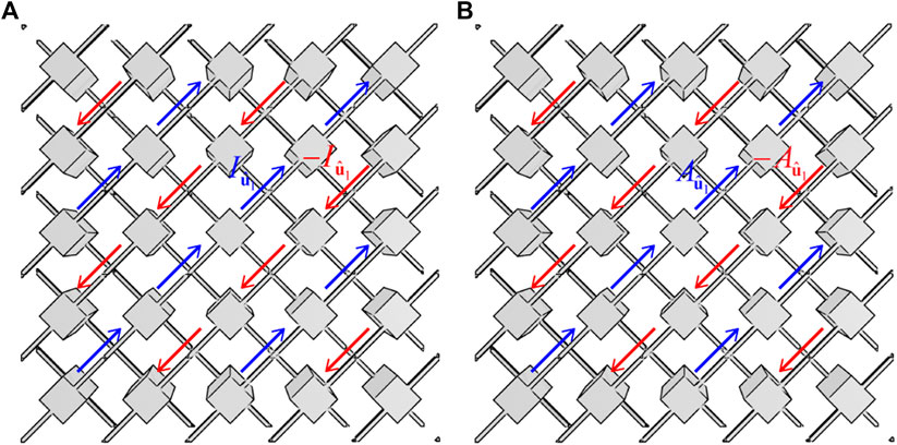
FIGURE 3. Periodic distributions of (A) currents and (B) the current-induced vector potentials on the double-mesh MM. Since the quasistatic mode is located at Brillouin zone corner M, the electric currents on the two meshes are out of phase (blue and red) and so do the vector potentials they induce. The inductance
For a perfect conductor, the microscopic electric field inside should vanish, and we have the following equation:
where the local potential difference Δφ satisfies Bloch theorem, and the voltage drop between two adjacent unit cells can be evaluated by the difference between the local potential differences of the two unit cells.
Combining Eqs. 1–4, we obtain the following generalized eigenvalue equation:
The equation has a nonzero eigenvector only when the determinant in Eq. 5 vanishes; then, the low-frequency dispersion can be derived as follows:
The band dispersion is controlled by two equivalent inductances and one equivalent capacitance mentioned above, which can be calculated in magnetostatic and electrostatic limits. Also, this model applies well for low frequencies, as long as the Bloch modes near the quasistatic mode (at the M point in this case) are considered (δkx and δky are sufficiently small compared to the reciprocal vector). Although the equivalent circuit model would deteriorate as the frequency increases, it still gives a qualitative prediction on the IFCs at midband frequency and can serve as a guideline for MM design.
From Eq. 6, the group velocities in
and can then be controlled by the equivalent capacitance and two equivalent inductances. Since the group velocities depend on the equivalent capacitance and inductances, the shape of the index ellipsoid can be controlled by adjusting the structural details of meshes, which determine the equivalent circuit parameters.
To investigate the dependence of group velocities on the structural parameters, we numerically calculate the equivalent inductances and capacitances of a series of double-mesh MMs. First, we alter the height of the metallic block centered at the unit cell while keeping other parameters unaltered (width wp = 0.4a and
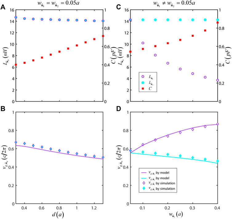
FIGURE 4. Tuning the group velocities of index ellipsoids by the inductances
In another case, we increase the
To further see the applicability of our model, Figures 5A,B plot the numerically simulated band structure and index ellipsoids for isotropic double-mesh MMs (height d = 0.8a, width wp = 0.4a, and
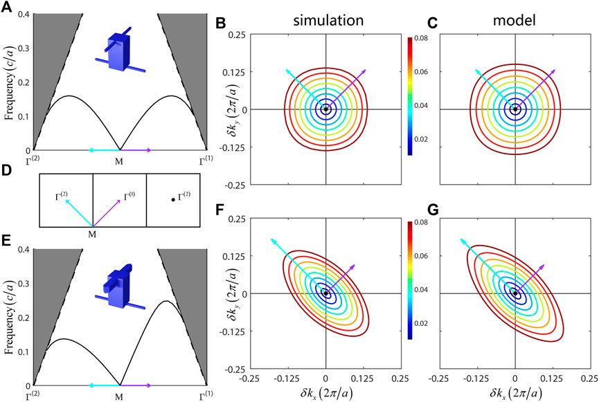
FIGURE 5. Shaping the index ellipsoids by introducing anisotropic inductances. (A) Simulated band dispersion and (B) corresponding IFCs for the isotropic MM shown in Figure 2A. In this case, the two metallic wires have the same bar width (height d = 0.8a, width wp = 0.4a, and
To see the influence for different equivalent inductances in
According to our circuit model, we can achieve isotropic or anisotropic shape of index ellipsoids at quasistatic limit by adjusting the equivalent inductances in
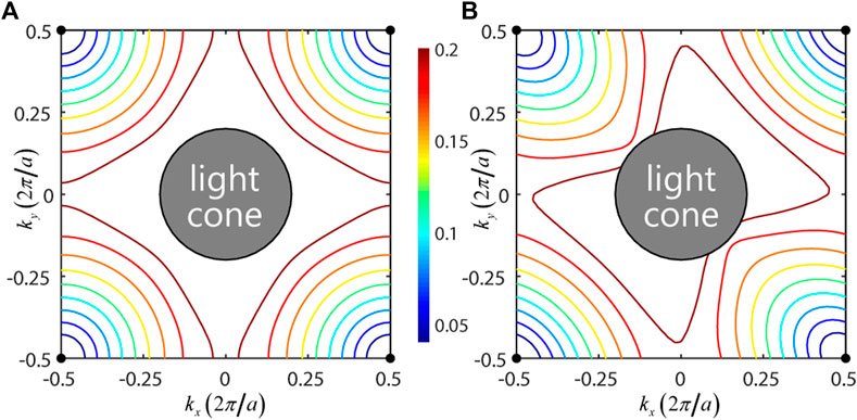
FIGURE 6. MMs with (A) cruciform-shaped or (B) bowtie-shaped IFCs (simulation). Structural parameters: in (A), height d = 0.42a, width wp = 0.4a, and
3 Conclusion
In conclusion, we propose an equivalent circuit model for connection-type MMs to analyze its low-frequency dispersion away from quasistatic limit, taking into account the mesh connectivity. The model implies that the low-frequency IFCs can be engineered via the equivalent inductances and capacitance of the metallic meshes. For instance, we adjust the metallic block height and the wire width according to the model and demonstrate the feasibility of shaping the low-frequency IFCs. Coupled with the degree of freedom of the quasistatic mode at an arbitrary k-point, one can, in principle, realize the arbitrary topology of IFCs and manipulate the EM propagation properties using an artificial medium.
Data Availability Statement
The original contributions presented in the study are included in the article/supplementary material, and further inquiries can be directed to the corresponding authors.
Author Contributions
WC and JD initiated and supervised the project. ZL and WC developed the theory. ZL performed the numerical simulations. ZL and WC wrote the draft. All authors contributed to the theoretical discussions, simulated data analysis, and manuscript writing.
Funding
This work was supported by the National Key R&D Program of China (Grant No. 2019YFA0706302), National Natural Science Foundation of China (Grant Nos. 62035016, 11874435, and 11904421), Natural Science Foundation of Guangdong Province (Grant No. 2018B030308005), Guangzhou Science, Technology, and Innovation Commission (Grant No. 201904010223), and Fundamental Research Funds for the Central Universities (Grant No. 20lgjc05 and 2021qntd27). ZX was supported by the National Science Foundation of China (Grant No. 11874432) and the National Key R&D Program of China (Grant No. 2019YFA0308200).
Conflict of Interest
The authors declare that the research was conducted in the absence of any commercial or financial relationships that could be construed as a potential conflict of interest.
Publisher’s Note
All claims expressed in this article are solely those of the authors and do not necessarily represent those of their affiliated organizations, or those of the publisher, the editors, and the reviewers. Any product that may be evaluated in this article, or claim that may be made by its manufacturer, is not guaranteed or endorsed by the publisher.
References
1. Fang A, Koschny T, Soukoulis CM. Optical Anisotropic Metamaterials: Negative Refraction and Focusing. Phys Rev B (2009) 79:245127. doi:10.1103/PhysRevB.79.245127
2. Krishnamoorthy HNS, Jacob Z, Narimanov E, Kretzschmar I, Menon VM. Topological Transitions in Metamaterials. Science (2012) 336:205–9. doi:10.1126/science.1219171
3. Poddubny AN, Belov PA, Kivshar YS. Purcell Effect in Wire Metamaterials. Phys Rev B (2013) 87:035136. doi:10.1103/PhysRevB.87.035136
4. Pendry JB, Holden AJ, Stewart WJ, Youngs I. Extremely Low Frequency Plasmons in Metallic Mesostructures. Phys Rev Lett (1996) 76:4773–6. doi:10.1103/PhysRevLett.76.4773
5. Pendry JB, Holden AJ, Robbins DJ, Stewart WJ. Magnetism from Conductors and Enhanced Nonlinear Phenomena. IEEE Trans Microwave Theor Techn. (1999) 47:2075–84. doi:10.1109/22.798002
6. Smith DR, Padilla WJ, Vier DC, Nemat-Nasser SC, Schultz S. Composite Medium with Simultaneously Negative Permeability and Permittivity. Phys Rev Lett (2000) 84:4184–7. doi:10.1103/PhysRevLett.84.4184
7. Smith DR, Pendry JB, Wiltshire MCK. Metamaterials and Negative Refractive index. Science (2004) 305:788–92. doi:10.1126/science.1096796
8. Simovski CR. Material Parameters of Metamaterials (A Review). Opt Spectrosc (2009) 107:726–53. doi:10.1134/s0030400x09110101
9. Liu Y, Zhang X. Metamaterials: a New Frontier of Science and Technology. Chem Soc Rev (2011) 40:2494–507. doi:10.1039/C0CS00184H
10. Sakai O, Tachibana K. Plasmas as Metamaterials: a Review. Plasma Sourc Sci. Technol. (2012) 21:013001. doi:10.1088/0963-0252/21/1/013001
11. Shelby RA, Smith DR, Schultz S. Experimental Verification of a Negative index of Refraction. Science (2001) 292:77–9. doi:10.1126/science.1058847
13. Smith DR, Schurig D. Electromagnetic Wave Propagation in media with Indefinite Permittivity and Permeability Tensors. Phys Rev Lett (2003) 90:077405. doi:10.1103/PhysRevLett.90.077405
14. Poddubny A, Iorsh I, Belov P, Kivshar Y. Hyperbolic Metamaterials. Nat Photon (2013) 7:948–57. doi:10.1038/nphoton.2013.243
15. Chigrin D, Enoch S, Sotomayor Torres C, Tayeb G. Self-guiding in Two-Dimensional Photonic Crystals. Opt Express (2003) 11:1203–11. doi:10.1364/OE.11.001203
16. Yu X, Fan S. Bends and Splitters for Self-Collimated Beams in Photonic Crystals. Appl Phys Lett (2003) 83:3251–3. doi:10.1063/1.1621736
17. Luo C, Johnson SG, Joannopoulos JD, Pendry JB. Subwavelength Imaging in Photonic Crystals. Phys Rev B (2003) 68:045115. doi:10.1103/PhysRevB.68.045115
18. Wang X, Ren ZF, Kempa K. Unrestricted Superlensing in a Triangular Two Dimensional Photonic crystal. Opt Express (2004) 12:2919–24. doi:10.1364/OPEX.12.002919
19. Salandrino A, Engheta N. Far-field Subdiffraction Optical Microscopy Using Metamaterial Crystals: Theory and Simulations. Phys Rev B (2006) 74:075103. doi:10.1103/PhysRevB.74.075103
20. Silveirinha MG, Belov PA, Simovski CR. Subwavelength Imaging at Infrared Frequencies Using an Array of Metallic Nanorods. Phys Rev B (2007) 75:035108. doi:10.1103/PhysRevB.75.035108
21. Witzens J, Loncar M, Scherer A. Self-collimation in Planar Photonic Crystals. IEEE J Select Top Quan Electron. (2002) 8:1246–57. doi:10.1109/JSTQE.2002.806693
22. Noori M, Soroosh M, Baghban H. Self-collimation in Photonic Crystals: Applications and Opportunities. Annalen der Physik (2018) 530:1700049. doi:10.1002/andp.201700049
23. Maslovski SI, Tretyakov SA, Belov PA. Wire media with Negative Effective Permittivity: A Quasi-Static Model. Microw Opt Technol Lett (2002) 35:47–51. doi:10.1002/mop.10512
24. Belov PA, Tretyakov SA, Viitanen AJ. Dispersion and Reflection Properties of Artificial media Formed by Regular Lattices of Ideally Conducting Wires. J Electromagn Waves Appl (2002) 16:1153–70. doi:10.1163/156939302x00688
25. Belov PA, Marqués R, Maslovski SI, Nefedov IS, Silveirinha M, Simovski CR, et al. Strong Spatial Dispersion in Wire media in the Very Large Wavelength Limit. Phys Rev B (2003) 67:113103. doi:10.1103/PhysRevB.67.113103
26. Nefedov IS, Viitanen AJ, Tretyakov SA. Propagating and Evanescent Modes in Two-Dimensional Wire media. Phys Rev E (2005) 71:046612. doi:10.1103/PhysRevE.71.046612
27. Silveirinha MG. Nonlocal Homogenization Model for a Periodic Array Ofϵ-Negative Rods. Phys Rev E (2006) 73:046612. doi:10.1103/PhysRevE.73.046612
28. Shin J, Shen J-T, Fan S. Three-dimensional Electromagnetic Metamaterials that Homogenize to Uniform Non-maxwellian media. Phys Rev B (2007) 76:113101. doi:10.1103/PhysRevB.76.113101
29. Maslovski SI, Silveirinha MG. Nonlocal Permittivity from a Quasistatic Model for a Class of Wire media. Phys Rev B (2009) 80:245101. doi:10.1103/PhysRevB.80.245101
30. Maslovski SI, Morgado TA, Silveirinha MG, Kaipa CSR, Yakovlev AB. Generalized Additional Boundary Conditions for Wire media. New J Phys (2010) 12:113047. doi:10.1088/1367-2630/12/11/113047
31. Simovski CR, Belov PA, Atrashchenko AV, Kivshar YS. Wire Metamaterials: Physics and Applications. Adv Mater (2012) 24:4229–48. doi:10.1002/adma.201200931
32. Latioui H, Silveirinha MG. Light Tunneling Anomaly in Interlaced Metallic Wire Meshes. Phys Rev B (2017) 96:195132. doi:10.1103/PhysRevB.96.195132
33. Chen W-J, Hou B, Zhang Z-Q, Pendry JB, Chan CT. Metamaterials with index Ellipsoids at Arbitrary K-Points. Nat Commun (2018) 9:2086. doi:10.1038/s41467-018-04490-4
34. Powell AW, Mitchell-Thomas RC, Zhang S, Cadman DA, Hibbins AP, Sambles JR. Dark Mode Excitation in Three-Dimensional Interlaced Metallic Meshes. ACS Photon (2021) 8:841–6. doi:10.1021/acsphotonics.0c01811
35. Sakhno D, Koreshin E, Belov PA. Longitudinal Electromagnetic Waves with Extremely Short Wavelength. Phys Rev B (2021) 104:L100304. doi:10.1103/PhysRevB.104.L100304
36. Wang H, Chen Q, Zetterstrom O, Quevedo-Teruel O. Three-dimensional Broadband and Isotropic Double-Mesh Twin-Wire media for Meta-Lenses. Appl Sci (2021) 11:7153. doi:10.3390/app11157153
37. Sakhno D, Koreshin E, Belov PA. Quadraxial Metamaterial. arXiv e-prints (2021), arXiv:2111.02230.
38. Du L, Yang A, Zayats AV, Yuan X. Deep-subwavelength Features of Photonic Skyrmions in a Confined Electromagnetic Field with Orbital Angular Momentum. Nat Phys (2019) 15:650–4. doi:10.1038/s41567-019-0487-7
39. Kim M, Lee D, Nguyen TH-Y, Lee H-J, Byun G, Rho J. Total Reflection-Induced Efficiency Enhancement of the Spin Hall Effect of Light. ACS Photon (2021) 8:2705–12. doi:10.1021/acsphotonics.1c00727
40. Deng Z-L, Shi T, Krasnok A, Li X, Alù A. Observation of Localized Magnetic Plasmon Skyrmions. Nat Commun (2022) 13:8. doi:10.1038/s41467-021-27710-w
Keywords: metamaterials, metallic meshes, isofrequency contours, quasistatic limit, equivalent circuit
Citation: Liao Z-L, Deng W-M, Xiang Z-L, Chen W-J and Dong J-W (2022) Topological Engineering of the Iso-Frequency Contours in Connection-Type Metamaterials. Front. Phys. 10:844049. doi: 10.3389/fphy.2022.844049
Received: 27 December 2021; Accepted: 21 January 2022;
Published: 18 February 2022.
Edited by:
Guancong Ma, Hong Kong Baptist University, Hong Kong SAR, ChinaCopyright © 2022 Liao, Deng, Xiang, Chen and Dong . This is an open-access article distributed under the terms of the Creative Commons Attribution License (CC BY). The use, distribution or reproduction in other forums is permitted, provided the original author(s) and the copyright owner(s) are credited and that the original publication in this journal is cited, in accordance with accepted academic practice. No use, distribution or reproduction is permitted which does not comply with these terms.
*Correspondence: Wen-Jie Chen , Y2hlbndlbmo1QG1haWwuc3lzdS5lZHUuY24=; Jian-Wen Dong , ZG9uZ2p3ZW5AbWFpbC5zeXN1LmVkdS5jbg==
 Zhao-Lin Liao
 Ze-Liang Xiang
 Wen-Jie Chen
  Jian-Wen Dong