 Ziyao Lyu
 Changshun Wang
94% of researchers rate our articles as excellent or good
Learn more about the work of our research integrity team to safeguard the quality of each article we publish.
Find out more
ORIGINAL RESEARCH article
Front. Phys., 21 February 2022
Sec. Chemical Physics and Physical Chemistry
Volume 10 - 2022 | https://doi.org/10.3389/fphy.2022.843852
This article is part of the Research TopicLight Manipulation in Novel Functional Materials and Waveguide StructuresView all 5 articles
Spin-orbital optical phenomena are closely related with light-matter interactions and have been of great interest in the last few years. Here, the effect of optical orbital angular momentum (OAM) on polarized waves carrying spin angular momentum (SAM) has been investigated experimentally by means of orbital polarization holography and analyzed with Jones matrices theoretically. We report that all-optical OAM-to-polarization manipulation can be realized with a controllable holographic grating recorded through the interference of orthogonally polarized beams in various helical modes in a kind of photo-alignment supermolecular liquid-crystalline films. The polarization states of diffraction beams can be controlled through adjusting the spatial degree of freedom of the recording light field. The OAM-controlled polarization manipulation is discussed in terms of Jones matrices and photoinduced birefringence. Because of the realization of OAM-to-SAM conversion, this work may find applications in a variety of devices.
Transfer of optical angular momentum (AM) has been proposed in the last few decades as an effective tool to achieve optical manipulation, quantum communication and so on [1, 2]. Generally, there are two kinds of AM carried by light, spin AM (SAM) and orbital AM (OAM). SAM is inherent in light beams with circular or elliptical polarization states and depends on the field vector rotations that take place in every point of the beam cross-section [3]. When the light is right- or left-handed circularly polarized (RCP or LCP), SAM equals ±ћ per photon, respectively [4]. Polarization is a fundamental property of electromagnetic fields and the polarization state of light has substantial influence in an increasing number of optical experiments and theoretical models [5]. In the field of optics, the polarization state of light can significantly affect the propagation of many fully or partially coherent paraxial light fields. Moreover, optical communications, laser science, microscopy and metrology demand control of light polarization [6–8]. On the other hand, optical vortex has become increasingly important recently [9, 10]. A vortex beam, with the spiral phase of exp(ilϕ) with l being the topological charge (TC) and ϕ being the azimuth angle, possesses intrinsic OAM [11]. OAM can be added to a Gaussian beam through a spiral phase plate (SPP) which is typically a high refractive index substrate that is shaped into the spiral phase ramp [3, 12]. The incident Gaussian beam is not deviated in direction and directly converted to a vortex beam. Like polarization, OAM of light provides the spatial degree of freedom, which can be of great benefit in many fields, such as holography [13, 14].
There are two important kinds of holography, namely polarization holography and OAM holography. In terms of polarization holography, the recording beams can be orthogonally circularly polarized and the interference field possesses constant light intensity with periodically distributed polarization in space [15–17]. Then, the polarization pattern is recorded and stored in photo-alignment materials. Polarization holography is an attractive technique for its unique capacity of recording intensity, phase, and polarization of a wave simultaneously along with the function of polarization modulation [18]. With the development of optical vortex, OAM holography also emerges as an effective method for data storage and information processing [19, 20]. Recently, there has been enormous interest in spin-orbit interactions of light [21, 22]. These are striking optical phenomena in which the polarization and spatial degrees of freedom of light affect each other. Traditionally, spin-orbit interactions in optics usually describe an influence of the polarization degree of freedom of light on its spatial properties [23–26]. However, the reverse process, i.e., OAM controls SAM, still needs more research.
In this article, polarization manipulation enabled by the spatial degree of freedom of light has been investigated experimentally by means of angular momentum holography, where SAM-OAM coupling takes place within the optical interference field during the process of light-matter interactions, resulting in the formation of a kind of photoinduced periodic birefringence structure in photo-alignment liquid crystals, namely the orbital polarization holographic grating (OPHG). We report that the polarization states of diffraction light from the recorded OPHG can be controlled through the spatial degree of freedom of recording light. The mechanism of OAM-to-SAM manipulation and the diffraction properties of OPHG are analyzed in terms of Jones matrices, and the photoinduced birefringence generated through SAM-OAM coupling as well as the transmission matrix of OPHG are calculated in order to interpret the effect of OAM-controlled polarization manipulation.
A kind of photo-alignment material through ionic self-assembly of poly ionic liquid and methyl orange dyes is chosen as the sample in this experiment because of the properties of strong photoinduced anisotropy and good thermal stability [27]. The charged polymer poly (1-butyl-vinylpyridinium bromide) is selected as the main chain and the methyl orange dye is selected as the building unit, as shown in Figure 1B. For the preparation of ionic self-assembly complex, 2 mg/ml poly ionic liquid aqueous solution is added to methyl orange aqueous solution at the molar charge ratio of 1:1. The precipitated complex is filtrated and washed several times with doubly distilled water, then dried in vacuum at 60°C for 12 h. The thickness of the liquid-crystalline film is 2 μm.
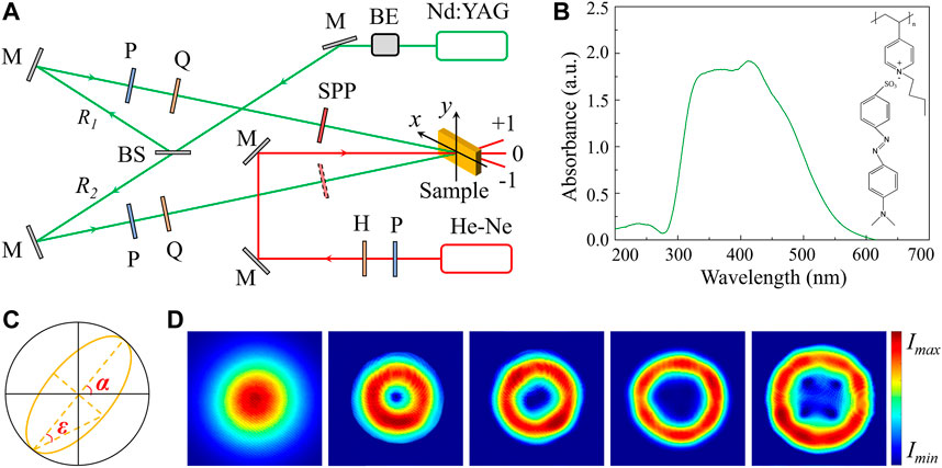
FIGURE 1. (A) Schematic setup of orbital polarization holography. BE, beam expander; M, mirror; BS, beam splitter; P, polarizer; Q, quarter-wave plate; H, half-wave plate; SPP, spiral phase plate. (B) Absorption spectrum and molecular structure of the photo-alignment liquid-crystalline film. (C) Diagram of the polarization ellipse with α being the azimuth and ɛ being the ellipticity. (D) Spatial intensity distribution of the recording light with TC of 0, 1, 2, 3 and 4 (from left to right) measured by CCD.
The experimental setup is depicted in Figure 1A. A 532 nm beam with the power density of 250 mW/cm2 from a Nd:YAG laser is selected as the pump light, according to the absorption spectrum of the sample in Figure 1B. The pump light passes through a beam expander and is divided by a 50:50 beam splitter. The two recording beams, marked as R1 and R2, are controlled to keep left- and right-handed circularly polarized, respectively. Then, an extra spiral phase is added to R1 or R2 in order to generate a vortex recording beam. The two recording beams interfere at the surface of the sample at an angle of 4° and the recording time is 100 s. The diffraction property of the recorded OPHGs is investigated through a 633 nm probe light with the power density of 150 mW/cm2 from a He-Ne laser. The diameters of the two recording beams are both 1.6 mm and the size of the probe light is controlled to be the same with that of the Gaussian recording beam in order to illuminate the whole OPHG. The spatial intensity distribution and polarization state of light are measured with CCD (CINOGY, CinCam-1201) and free-space polarimeter (THORLABS, PAX5710VIS-T), respectively. As shown in Figure 1C, the polarization state detected with the polarimeter is presented as a polarization ellipse that can be described with two parameters, azimuth α and ellipticity ɛ, related to Stokes parameters. In terms of the spatial intensity distribution of the vortex recording light in Figure 1D, there is no change for the laser spot when the polarization state varies from LCP to RCP under all four TC conditions. The polarization state also keeps constant with TC being manipulated [28]. For ease of description, the recorded OPHG is expressed as OPHG (lRi = n) with Ri being the vortex recording light and n being the value of TC. The distributions of light intensities under four TC conditions are presented in Figure 2. Because the two recording beams are orthogonally polarized, the total light intensities of the interference fields are the sum of the intensities of R1 and R2 without interference fringes and only the polarization state changes periodically in space [29].
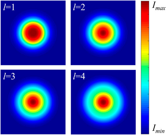
FIGURE 2. Light intensity distribution within the orbital polarization holographic recording field when the value of TC increases from 1 to 4. The total intensities of the interference fields are the sum of the intensities of the two recording beams without interference fringes.
First of all, OPHG (lR1 = 1) is recorded. The probe light is linearly polarized and the polarization direction is rotated counterclockwise through a half-wave plate, i.e., αp is modulated from −90° to 90°. The polarization state of probe light changes in the same way in subsequent experiments. As OAM is added to the holographic recording field, the polarization state of the zeroth-order diffraction light is controlled to be left-handed elliptically polarized, as reported on the Poincaré sphere in Figure 3A, which is different from the convention holographic grating whose polarization state is not modulated. The zeroth diffraction order of OPHG (lR1 = 1) is regulated to possess SAM and the ellipticity almost remains constant (−21.75°≤ε ≤ −19.48°) as the polarization direction of the probe light rotates in a circle. Then, we remove the SPP and record another polarization holographic grating (PHG) as a comparison and the experimental results are presented in Figure 3B. According to Figures 3A,B, the polarization state of the zeroth-order diffraction light from PHG keeps the same with that of incident light, and thus SAM manipulation is attributed to the spatial degree of freedom of recording light through orbital polarization holography. Besides, Figure 3C presents that, for OPHG (lR1 = 1), the azimuth of the elliptically polarized zeroth-order diffraction light is not regulated by OAM and keeps the same with that of the probe light.
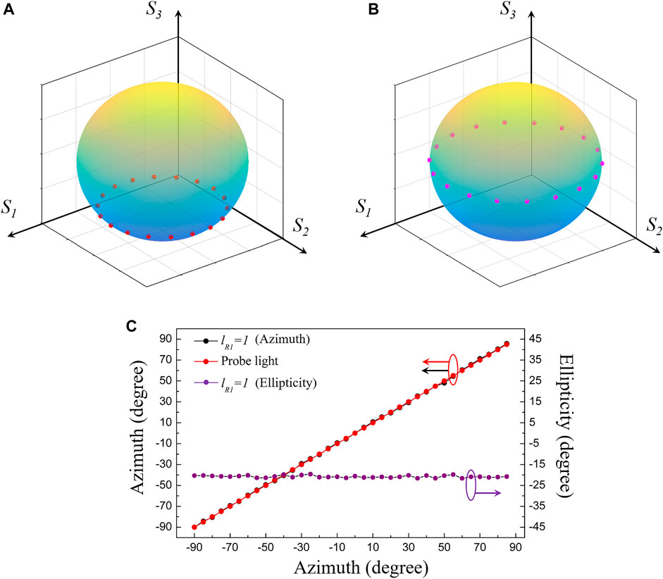
FIGURE 3. (A) Orbital-to-spin AM manipulation through OPHG (lR1 = 1) presented on the Poincaré sphere. S1-S3 are normalized Stokes parameters. (B) Unmodulated polarization states of the zeroth diffraction order from PHG recorded through the holographic light field without spatial degree of freedom as a comparison. (C) The azimuth of the elliptically polarized zeroth-order diffraction light from OPHG (lR1 = 1) is not regulated by OAM and remains the same with that of the probe light. Moreover, the value of ellipticity almost keeps constant as the polarization direction of the probe light rotates at an interval of 5°.
As the probe light illuminates the recorded OPHG (lR1 = 1), the ± 1st diffraction orders with the diffraction efficiency of 9.83% are detected and the polarization states are presented in Figure 4. It can be noticed that both of the ± 1st order diffraction beams are modulated to be elliptically polarized by OPHG (lR1 = 1) and the value of ellipticity varies with the polarization direction of probe light. The diffraction property of the recorded OPHG is also different from that of PHG under the same experimental conditions [17]. As OAM is added to the holographic interference field, the polarization state of diffraction light from OPHG (lR1 = 1) can be modulated and the modulation depth is dependent on the spatial degree of freedom of recording light.
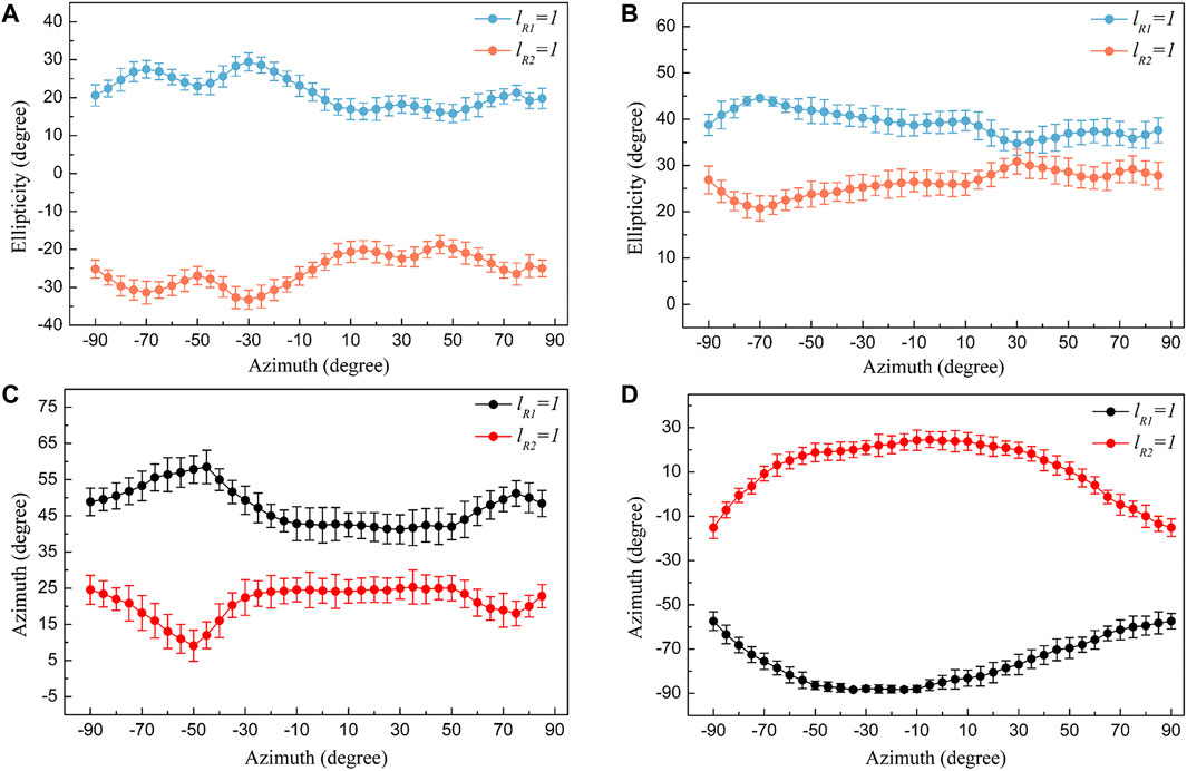
FIGURE 4. Polarization manipulation through orbital polarization holography when TC = 1. Symmetrical ellipticity control of the −1st (A) and +1st (B) diffraction orders from OPHGs (lR1 = 1 and lR2 = 1) with the polarization direction of the probe light being modulated from −90° to 90° at an interval of 5°. Similar to the ellipticity, the azimuth of the −1st (C) and +1st order (D) polarized diffraction light from the two OPHGs is controlled to change conversely.
Then, OPHG (lR1 = 1) is erased through the heating method. The sample is heated up to 60°C, in which thermally randomizing the molecular orientations occurs. This writing-erasing cycle could be repeated over 100 times on the same spot of the film without fatigue. Another OPHG (lR2 = 1) is recorded and the diffraction efficiency of the ± 1st diffraction order is 12.82%. The polarization states of the ± 1st order diffraction light from OPHG (lR2 = 1) are presented in Figure 4. The −1st order diffraction light is modulated to be right-handed elliptically polarized while the other one becomes left-handed elliptically polarized. The experimental results indicate that polarization manipulation enabled by the spatial degree of freedom of light still exists when the handedness of SAM within the orbital polarization holographic recording field is reversed. However, the polarization changing behaviors of the 1st order diffraction light are not the same with those of OPHG (lR1 = 1). Firstly, the ellipticity of the same diffraction order from the two OPHGs is investigated. In Figure 4A, it can be noticed that the changing behaviors of ellipticity of the -1st order diffraction beams from OPHGs (lR1 = 1 and lR2 = 1) are symmetrical as αp increases from −90° to 90° at an interval of 5°. In terms of the +1st diffraction order, similar experiment results are obtained, as shown in Figure 4B. As the ellipticity of the polarized diffraction light from OPHG (lR1 = 1) increases or decreases, the ellipticity of the same diffraction order from OPHG (lR2 = 1) goes through the reverse process. Moreover, the symmetrical variation behavior also occurs to the azimuth of the polarization ellipse, as presented in Figures 4C,D. With the polarization direction of the probe light rotating, the azimuth of the same diffraction order from the two OPHGs varies conversely.
After reversing the handedness of SAM within the orbital polarization holographic recording field in the previous section, we investigate the effect of spatial degree of freedom of light on polarization manipulation. Similar to OPHGs (lR1 = 1 and lR2 = 1), ±1st order diffraction beams from OPHGs are detected as OAM increases and the diffraction efficiency is listed as: 7.53% (lR1 = 2), 13.47% (lR2 = 2), 5.36% (lR1 = 3), 13.18% (lR2 = 3), 3.08% (lR1 = 4) and 10.82% (lR2 = 4). Firstly, the ellipticity of the ±1st order diffraction light from the recorded OPHGs is measured and the results are presented in Figure 5. In terms of OPHGs (lR1 = 2 and lR2 = 2) in Figures 5A,B, the ellipticity of the same diffraction order is still manipulated symmetrically due to the handedness change of the SAM in the spin-orbital interference field. However, as the effect of OAM continues to be enhanced, the symmetry is broken and the changing behaviors of ellipticity of the 1st order diffraction beams from OPHGs (lR1 = 3 and lR2 = 3) (Figures 5C,D) and OPHGs (lR1 = 4 and lR2 = 4) (Figures 5E,F) tend to be controlled synchronously. For example, in terms of the +1st order diffraction beams from OPHG (lR1 = 4) and OPHG (lR2 = 4) in Figure 5F, the ellipticity of both diffraction beams start to decrease first, then becomes larger, and decrease again in one period. On the other hand, the ellipticity of the zeroth-order diffraction light almost keeps constant and the measurements are listed as: (−11.13°≤ε ≤ −9.46°) for OPHG (lR1 = 2), (−7.49°≤ε ≤ −5.16°) for OPHG (lR1 = 3), (−14.64°≤ε ≤ −12.15°) for OPHG (lR1 = 4), (−6.24°≤ε ≤ −4.57°) for OPHG (lR2 = 2), (12.26°≤ε ≤ 14.73°) for OPHG (lR2 = 3) and (5.19°≤ε ≤ 7.41°) for OPHG (lR2 = 4). Then, we focus on the situation that SPPs with different TCs are fixed in R1 optical path, as shown in Figures 5G,H. Taking the +1st diffraction order from OPHGs (lR1 = 1–4) as an example (see Figure 5H), the ellipticity decreases first and then keeps an upward tendency with TC increasing from 1 to 4, regardless of the polarization direction of the probe light. Similarly, the ellipticity of the diffraction light from OPHGs (lR2 = 1–4) is also controlled by OAM to vary synchronously.
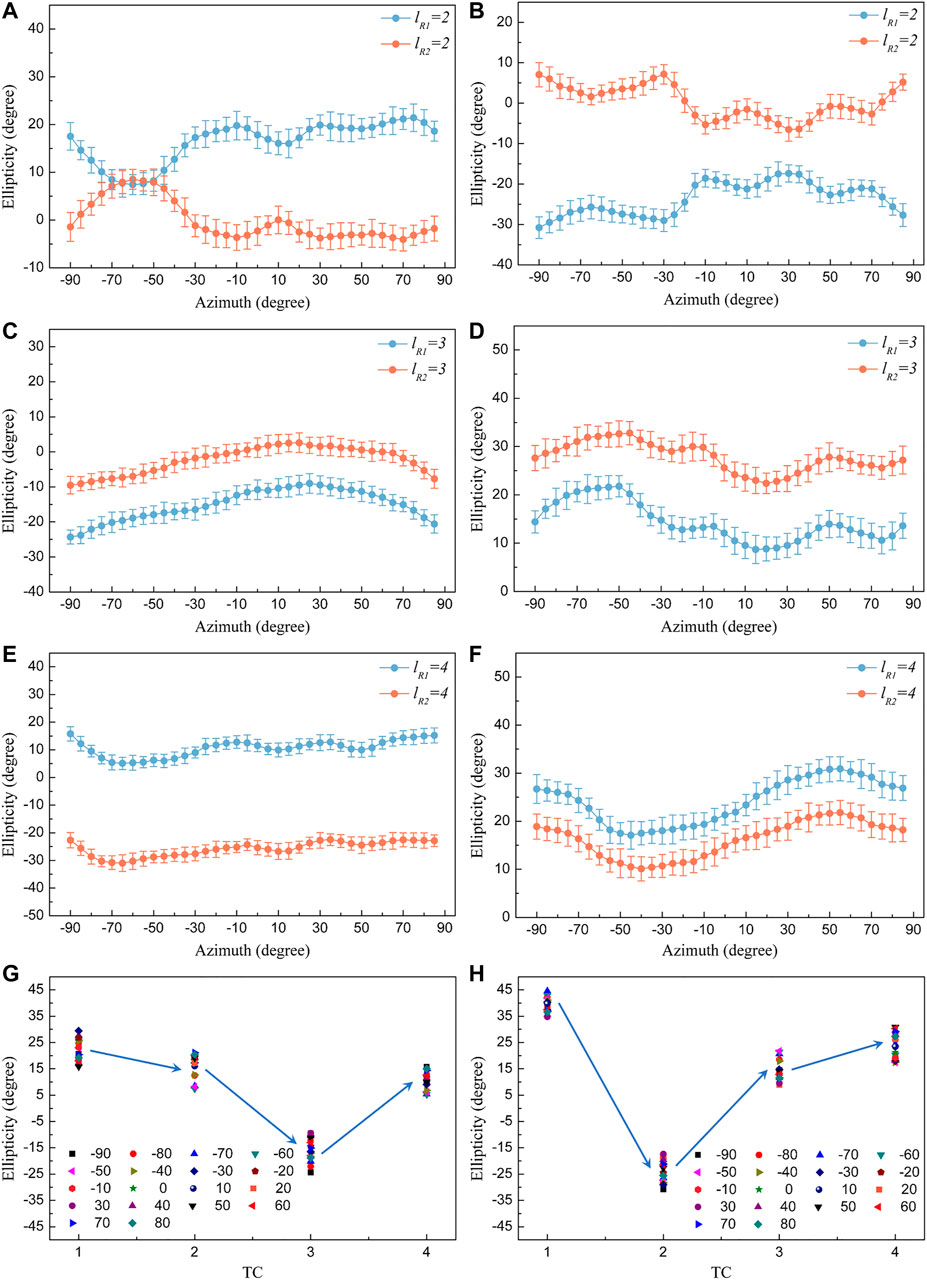
FIGURE 5. Under the effect of the spatial degree of freedom of recording light on polarization manipulation, the ellipticity of the (A) −1st and (B) +1st order diffraction light from OPHG (lR1 = 2) and OPHG (lR2 = 2) is regulated symmetrically when αp changes from −90° to 90° at an interval of 5°. With TC increasing, the ellipticity symmetry breaking occurs and the ellipticity of the (C) −1st and (D) +1st diffraction orders from OPHGs (lR1 = 3 and lR2 = 3) varies in a similar trend. Synchronous ellipticity modulation of the (E) −1st and (F) +1st order diffraction beams from OPHG (lR1 = 4) and OPHG (lR2 = 4). OAM-controlled ellipticity variation of the (G) −1st and (H) +1st diffraction orders from OPHGs (lR1 = 1–4) as TC increases from 1 to 4.
In addition to ellipticity, the azimuth of the ±1st diffraction order is also modulated by OPHGs, as shown in Figure 6. Analogue to the orbit-controlled ellipticity in Figures 5G,H, the azimuth of diffraction light also tends to be regulated synchronously by OAM when the SPPs are fixed in one optical path. Figures 6A,B report the changing behaviors of azimuth of the ±1st order diffraction light from OPHGs (lR1 = 1–4), respectively. The values of azimuth all go through the increasing-decreasing-increasing processes as TC rises from 1 to 4, whatever the polarization direction of the probe light is. In contrast, for the zeroth diffraction order, the azimuth increases with that of the probe light and there is no obvious difference under four TC conditions, as shown in Figure 6C. On the other hand, OAM-controlled azimuth modulation also occurs to the 1st diffraction order of OPHGs (lR2 = 1–4). When TC = 2 in Figures 6D,E, the azimuth of the ±1st order diffraction light from OPHGs (lR1 = 2 and lR2 = 2) is still modulated to change symmetrically. In terms of the ±1st order diffraction light from OPHGs (lR1 = 3 and lR2 = 3) in Figures 6F,G, the symmetry no longer holds and the variation of azimuth tends to be consistent because of the variation of spin-orbit interaction within the recording light field, where the effect of OAM on the polarization state of the diffraction light is enhanced. Similar results can also be obtained for OPHGs (lR1 = 4 and lR2 = 4) in Figure 6H. In this section, the effect of spatial degree of freedom of light on polarization manipulation is demonstrated experimentally by means of orbital polarization holography.
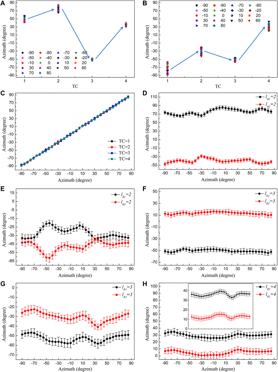
FIGURE 6. OAM-controlled azimuth variation of the (A) −1st and (B) +1st diffraction orders from OPHGs (lR1 = 1–4) as TC of the vortex recording light increases from 1 to 4. (C) The azimuth of the zeroth-order diffraction light is not modulated by OPHGs, regardless of the value of TC. When TC = 2, the azimuth of the (D) −1st and (E) +1st order diffraction light from OPHGs (lR1 = 2 and lR2 = 2) is controlled to vary symmetrically. With TC continuing to increase, the effect of OAM is enhanced and the azimuth of the (F) −1st and (G) +1st diffraction order from OPHGs (lR1 = 3 and lR2 = 3) tends to vary synchronously. (H) Similar azimuth modulation of the +1st diffraction order enabled by spin-orbit coupling when TC = 4. Inset: azimuth of the −1st order diffraction light from OPHGs (lR1 = 4 and lR2 = 4).
Orbital polarization holography in photo-alignment liquid crystals is attributed to the interaction between the optical torques induced by SAM (τS) and OAM (τO) which leads to molecular reorientation, resulting in the formation of a kind of AM-induced birefringence in the sample. Firstly, in terms of the effect of SAM on molecular reorientation, the absorption probability of the trans-isomers of liquid crystals is proportional to N [30]
With < > representing the statistical average, P being the unit vector of the polarization of the interference light field, M(LQ) being the electric dipole transition moment of liquid crystals and θ being the angle between P and M(LQ). According to Eq. 1, when N is not equal to 0, liquid crystals will absorb pump light and tend to be reoriented under the force of τS. During this process, reversible trans-cis-trans photoinduced isomerizations of liquid crystals take place under the action of polarized light. Due to the angular-selective character of light absorption, liquid crystals become uniaxially oriented in a plane perpendicular to the polarization direction of incident light after numerous repetitive isomerization cycles [15]. By virtue of the τS-induced reorientation process, SAM-induced birefringence ΔnSAM is formed in the sample. Because the polarization direction within the RCP-LCP interference field varies periodically, ΔnSAM changes regularly with P. On the other hand, when the polarized light field contains OAM, the orientation of liquid crystals is also forced by an OAM-induced torque τO that is in the azimuthal direction of OAM [31]. Under the effect of OAM, τO-induced deflection of molecular reorientation occurs and the liquid crystals are no longer perpendicular to the polarization direction, which exerts an influence on the SAM-induced birefringence. Thus, molecular rearrangement within the orbital polarization holographic recording field is based on τS and affected by τO, leading to the formation of a kind of AM-induced birefringence ΔnAM. The periodically distributed AM-induced birefringence generated through spin-orbit coupling is contributed to the formation of OPHG and its diffraction properties.
Based on the discussion above, the value of ΔnAM is calculated to interpret OAM-enabled polarization manipulation. We start from the transmission matrix of OPHG. Let us consider the Jones matrix of a general anisotropic element
The anisotropic phase retardation is
Where the rotation matrix is
The polarization state of the 1st order diffraction light is calculated as
Where RP represents the Jones vector of the linearly polarized probe light. According to Eq. 6, the LCP and RCP components of the probe light are divided and converted into RCP and LCP, respectively.
In terms of OPHG, SAM-induced molecular reorientation is affected by τO and OAM-induced birefringence is formed within the recording area. In this case,
In order to calculate the value of ΔnAM, we start from the zeroth-order transmission matrix
With δ0 and η0 being the phase and diffraction efficiency of the zeroth diffraction order, respectively. Based on the experimental results, the azimuth of the zeroth-order diffraction light α0 is not modulated by OPHG and we obtain
With ε0 being the ellipticity of the zeroth-order diffraction light. Then, AM-induced birefringence ΔnAM can be calculated as follows
In which α ± 1, ε ± 1, δ ± 1 and η ± 1 represent the azimuth, ellipticity, phase and diffraction efficiency of the ±1st order diffraction light, respectively. According to Eqs 7, 9, 10, the equation of ΔnAM is
Similar to the SAM condition, the phases of the ±1st order diffraction light are the functions of γ and αp. Based on the experimental data, the plural numerator is proportional to the plural denominator in Eq. 11 and the ratio is a real number. The values of ΔnAM under our experimental conditions are calculated to equal 0.068 (ΔnSAM), 0.063 (lR1 = 1), 0.072 (lR2 = 1), 0.055 (lR1 = 2), 0.074 (lR2 = 2), 0.046 (lR1 = 3), 0.073 (lR2 = 3), 0.035 (lR1 = 4), 0.066 (lR2 = 4), respectively. Taking OPHGs (lR1 = 1 and lR2 = 1) as examples, theoretical simulations of orbital polarization holographic manipulation are presented in Figure 7, and there is a good agreement between the theoretical analysis and experimental results. Moreover, it can be noticed that ΔnAM is always smaller than ΔnSAM and continues to be attenuated when lR1 increases from 1 to 4. In contrast, the value of ΔnAM increases with the enhancement of OAM carried by R2 recording light at first, while starts to decrease when lR2≥3. The reason is that, when SPPs are placed in the optical path of R1, the effect of OAM weakens the component of SAM-induced birefringence in the sample during the process of spin-orbit coupling. On the other hand, when TC increases, the size of singularity of the vortex recording beam becomes larger and the light intensity within the spatially limited interference area decreases. Under the combined weakening effects of OAM and light intensity, ΔnAM decreases significantly from 0.068 to 0.035 when lR1 rises to 4. When R2 becomes the vortex light, SAM handedness of the interference field is reversed and the SAM-induced birefringence is enhanced by OAM, leading to the increase of ΔnAM. In the case of lR2 = 3 and 4, though the value of TC becomes larger, the weakening effect of light intensity is greater than the enhancing effect of OAM, leading to the decrease of ΔnAM. In this section, the mechanism of polarization manipulation enabled through orbital polarization holography has been explained theoretically.
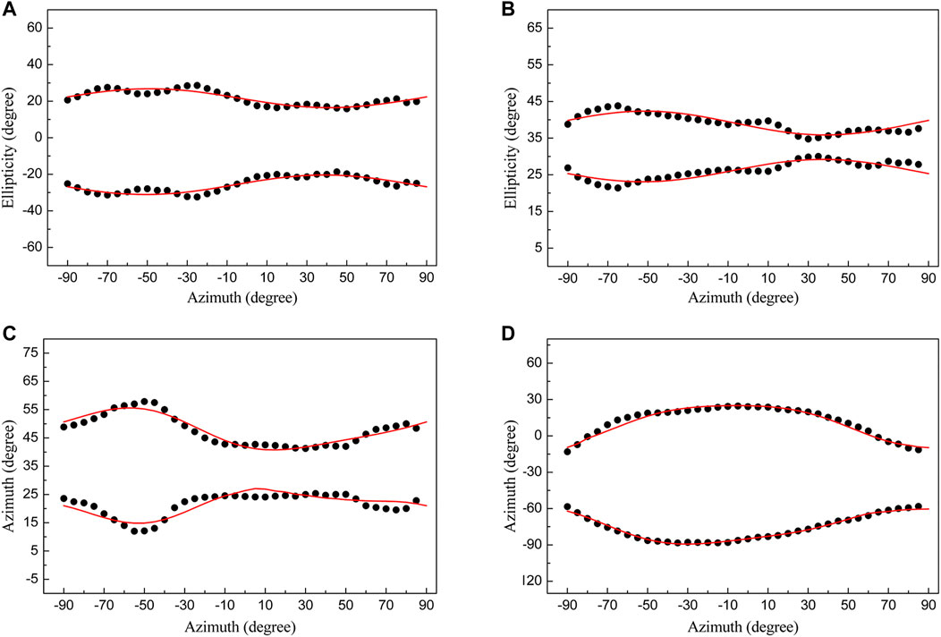
FIGURE 7. Simulated curves and experimental data of orbital polarization holographic manipulation in terms of OPHGs (lR1 = 1 and lR2 = 1). Figures 7A–D and Figures 4A–D are in one-to-one correspondence. There is an agreement between the theoretical analysis and experimental results.
In conclusion, all-optical polarization manipulation through orbital polarization holography has been demonstrated experimentally and analyzed theoretically with Jones matrices. The polarization states of diffraction light from the recorded OPHGs are able to be controlled regularly under the effect of spatial degree of freedom of recording light because of optical SAM-OAM coupling during the process of light-matter interactions, resulting in the formation of a kind of periodically distributed AM-induced birefringence structure in photo-alignment liquid crystals. Furthermore, the transmission matrix of OPHGs and the value of AM-induced birefringence are calculated with Jones matrices in order to interpret the mechanism of orbit-controlled polarization manipulation. Based on the previous research on SAM-to-OAM conversion, orbit-induced polarization modulation is realized in this work, which may enrich the field of optical manipulation.
The original contributions presented in the study are included in the article/Supplementary Material, further inquiries can be directed to the corresponding author.
ZL: performed the experiments, processed and analysed the data, and wrote the article; CW: performed part of the experiments, reviewed the paper and provided technical assistance. All authors approved the final version of the article.
This work is supported by National Natural Science Foundation of China (NSFC) (grant 92050116).
The authors declare that the research was conducted in the absence of any commercial or financial relationships that could be construed as a potential conflict of interest.
All claims expressed in this article are solely those of the authors and do not necessarily represent those of their affiliated organizations, or those of the publisher, the editors and the reviewers. Any product that may be evaluated in this article, or claim that may be made by its manufacturer, is not guaranteed or endorsed by the publisher.
1. Perreault WE, Zhou H, Mukherjee N, Zare RN. A Bi-axial Quantum State that Controls Molecular Collisions like a Double-Slit Interferometer. Front Phys (2021) 9:671997. doi:10.3389/fphy.2021.671997
2. Bandrauk AD, Chelkowski S, Yuan K-J. Electronic Currents and Magnetic Fields in H2+ Induced by Coherent Resonant Bichromatic Circularly Polarized Laser Pulses: Effects of Orientation, Phase, and Helicity. Front Phys (2021) 9:675375. doi:10.3389/fphy.2021.675375
3. Bekshaev A, Vasnetsov M. Vortex Flow of Light: "Spin" and "Orbital" Flows in a Circularly Polarized Paraxial Beam. In: Twisted Photons: Applications of Light with Orbital Angular Momentum. Weinheim: Wiley-VCH Verlag GmbH & Co. KGaA (2011). p. 13–24. doi:10.1002/9783527635368.ch2
4. Xiao W, Chen Y, Han K, Shen X, Wang W. Tailoring Spin Angular Momentum of Light: Design Principles for Plasmonic Nanostructures. Phys Rev Appl (2020) 13:014029. doi:10.1103/physrevapplied.13.014029
5. de Aguiar HB, Gigan S, Brasselet S. Polarization Recovery through Scattering media. Sci Adv (2017) 3:e1600743. doi:10.1126/sciadv.1600743
6. Nicholls LH, Rodríguez-Fortuño FJ, Nasir ME, Córdova-Castro RM, Olivier N, Wurtz GA, et al. Ultrafast Synthesis and Switching of Light Polarization in Nonlinear Anisotropic Metamaterials. Nat Photon (2017) 11:628–33. doi:10.1038/s41566-017-0002-6
7. Plutenko DO, Vasnetsov MV. Scattering of the Radial Polarized Beams on the Metal Spherical Particle: Plasmonic Nanojet Formation. Front Phys (2021) 9:727525. doi:10.3389/fphy.2021.727525
8. Sarmiento-Merenguel JD, Halir R, Le Roux X, Alonso-Ramos C, Vivien L, Cheben P, et al. Demonstration of Integrated Polarization Control with a 40 dB Range in Extinction Ratio. Optica (2015) 2:1019–23. doi:10.1364/optica.2.001019
9. Li X, Zhou Y, Cai Y, Zhang Y, Yan S, Li M, et al. Generation of Hybrid Optical Trap Array by Holographic Optical Tweezers. Front Phys (2021) 9:591747. doi:10.3389/fphy.2021.591747
10. Zhang Z, Qiao X, Midya B, Liu K, Sun J, Wu T, et al. Tunable Topological Charge Vortex Microlaser. Science (2020) 368:760–3. doi:10.1126/science.aba8996
11. Puentes G, Banerji A. Generation of High-Order Vortex States from Two-Mode Squeezed States. Front Phys (2021) 9:690721. doi:10.3389/fphy.2021.690721
12. Oemrawsingh SSR, van Houwelingen JAW, Eliel ER, Woerdman JP, Verstegen EJK, Kloosterboer JG, et al. Production and Characterization of Spiral Phase Plates for Optical Wavelengths. Appl Opt (2004) 43:688–94. doi:10.1364/ao.43.000688
13. Ren H, Briere G, Fang X, Ni P, Sawant R, Héron S, et al. Metasurface Orbital Angular Momentum Holography. Nat Commun (2019) 10:2986. doi:10.1038/s41467-019-11030-1
14. Fang X, Ren H, Gu M. Orbital Angular Momentum Holography for High-Security Encryption. Nat Photon (2020) 14:102–8. doi:10.1038/s41566-019-0560-x
15. Ryabchun A, Sakhno O, Stumpe J, Bobrovsky A. Full-Polymer Cholesteric Composites for Transmission and Reflection Holographic Gratings. Adv Opt Mater (2017) 5:1700314. doi:10.1002/adom.201700314
16. Callegari F, Le Gratiet A, Zunino A, Mohebi A, Bianchini P, Diaspro A. Polarization Label-free Microscopy Imaging of Biological Samples by Exploiting the Zeeman Laser Emission. Front Phys (2021) 9:758880. doi:10.3389/fphy.2021.758880
17. Cazac V, Achimova E, Abashkin V, Prisacar A, Loshmanschii C, Meshalkin A, et al. Polarization Holographic Recording of Vortex Diffractive Optical Elements on Azopolymer Thin Films and 3D Analysis via Phase-Shifting Digital Holographic Microscopy. Opt Express (2021) 29:9217–30. doi:10.1364/oe.415639
18. Zang J, Kang G, Li P, Liu Y, Fan F, Hong Y, et al. Dual-channel Recording Based on the Null Reconstruction Effect of Orthogonal Linear Polarization Holography. Opt Lett (2017) 42:1377–80. doi:10.1364/ol.42.001377
19. Shen Y, Wang X, Xie Z, Min C, Fu X, Liu Q, et al. Optical Vortices 30 Years on: OAM Manipulation from Topological Charge to Multiple Singularities. Light Sci Appl (2019) 8:90. doi:10.1038/s41377-019-0194-2
20. Lyu Z, Wang C. All-optically Phase-Induced Polarization Modulation by Means of Holographic Method. Sci Rep (2020) 10:5657. doi:10.1038/s41598-020-62549-z
21. Bliokh KY, Rodríguez-Fortuño FJ, Nori F, Zayats AV. Spin-orbit Interactions of Light. Nat Photon (2015) 9:796–808. doi:10.1038/nphoton.2015.201
22. Georgi P, Schlickriede C, Li G, Zhang S, Zentgraf T. Rotational Doppler Shift Induced by Spin-Orbit Coupling of Light at Spinning Metasurfaces. Optica (2017) 4:1000–5. doi:10.1364/optica.4.001000
23. Devlin RC, Ambrosio A, Rubin NA, Mueller JPB, Capasso F. Arbitrary Spin-To-Orbital Angular Momentum Conversion of Light. Science (2017) 358:896–901. doi:10.1126/science.aao5392
24. Arzola AV, Chvátal L, Jákl P, Zemánek P. Spin to Orbital Light Momentum Conversion Visualized by Particle Trajectory. Sci Rep (2019) 9:4127. doi:10.1038/s41598-019-40475-z
25. Zhao Y, Edgar JS, Jeffries GD, McGloin D, Chiu DT. Spin-to-Orbital Angular Momentum Conversion in a Strongly Focused Optical Beam. Phys Rev Lett (2007) 99:073901. doi:10.1103/PhysRevLett.99.073901
26. Saito S. Poincaré Rotator for Vortexed Photons. Front Phys (2021) 9:646228. doi:10.3389/fphy.2021.646228
27. Xiao S, Lu X, Lu Q. Photosensitive Polymer from Ionic Self-Assembly of Azobenzene Dye and Poly(ionic Liquid) and its Alignment Characteristic toward Liquid crystal Molecules. Macromolecules (2007) 40:7944–50. doi:10.1021/ma070972s
28. Gregg P, Kristensen P, Rubano A, Golowich S, Marrucci L, Ramachandran S. Enhanced Spin Orbit Interaction of Light in Highly Confining Optical Fibers for Mode Division Multiplexing. Nat Commun (2019) 10:4707. doi:10.1038/s41467-019-12401-4
29. Li Y, Kim J, Escuti MJ. Orbital Angular Momentum Generation and Mode Transformation with High Efficiency Using Forked Polarization Gratings. Appl Opt (2012) 51:8236–45. doi:10.1364/ao.51.008236
30. Tawa K, Kamada K, Kiyohara K, Ohta K, Yasumatsu D, Sekkat Z, et al. Photoinduced Reorientation of Azo Dyes Bonded to Polyurethane Studied by Polarized FT-IR Spectroscopy. Macromolecules (2001) 34:8232–8. doi:10.1021/ma002009r
Keywords: Jones matrix, polarization control, photoinduced birefringence, spin-orbit interaction, holography
Citation: Lyu Z and Wang C (2022) All-Optical Polarization Manipulation Through Orbital Polarization Holography. Front. Phys. 10:843852. doi: 10.3389/fphy.2022.843852
Received: 27 December 2021; Accepted: 31 January 2022;
Published: 21 February 2022.
Edited by:
Tingchao He, Shenzhen University, ChinaReviewed by:
Wenbo Hu, Northwestern Polytechnical University, ChinaCopyright © 2022 Lyu and Wang. This is an open-access article distributed under the terms of the Creative Commons Attribution License (CC BY). The use, distribution or reproduction in other forums is permitted, provided the original author(s) and the copyright owner(s) are credited and that the original publication in this journal is cited, in accordance with accepted academic practice. No use, distribution or reproduction is permitted which does not comply with these terms.
*Correspondence: Changshun Wang, Y3N3YW5nQHNqdHUuZWR1LmNu
Disclaimer: All claims expressed in this article are solely those of the authors and do not necessarily represent those of their affiliated organizations, or those of the publisher, the editors and the reviewers. Any product that may be evaluated in this article or claim that may be made by its manufacturer is not guaranteed or endorsed by the publisher.
Research integrity at Frontiers
Learn more about the work of our research integrity team to safeguard the quality of each article we publish.