 Nan Jiang
 Qingli Zhou
95% of researchers rate our articles as excellent or good
Learn more about the work of our research integrity team to safeguard the quality of each article we publish.
Find out more
ORIGINAL RESEARCH article
Front. Phys. , 16 February 2022
Sec. Optics and Photonics
Volume 10 - 2022 | https://doi.org/10.3389/fphy.2022.840090
This article is part of the Research Topic Application of Terahertz Frequency in Substance Detection and Recognition View all 9 articles
Combined with experimental and simulated results, the resonances and metamaterial-induced transparency have been theoretically investigated using the Lorentz oscillator model for terahertz metamaterials with unequal-length bar structures. The bar spacing has an impact on the spectral evolution, implying that the coupling between metal bars varies correspondingly in one unit cell and the adjacent cells. Different from the evidence that the strongest coupling occurs in double bar structures when the bar spacing is uniform in the entire sample, the coupling in 3 bar structures is more complicated due to the weakened coupling with the middle bar and increased coupling between the other 2 bars by further increasing the bar spacing. The dependence of calculated transmission spectra on the damping rate and coupling coefficient is demonstrated, showing that the fitting parameters could control and tune the resonant dips, the transparency peaks, and even the quality factors of the spectra regularly. Furthermore, the sensing properties have been investigated by simulating the spectral evolution with the overlayers of different refractive indices to optimize the sensing parameters. Our obtained results could advance the understanding of resonance coupling and offer the possibility to further study the modulation and biosensing in the coupled terahertz devices.
Artificially engineered materials, usually known as metamaterials, have exhibited novel electromagnetic phenomena which do not exist in natural materials, such as negative refractive index [1, 2], electromagnetic cloaking [3–6], sensing [7, 8], and near-perfect absorption [9, 10]. The elimination of absorption via quantum interference in an atomic medium is termed as electromagnetically induced transparency (EIT) [11–15] but now can be mimicked by non-quantum approaches. Recently, analogs of the EIT-like behavior, plasmon-induced transparency (PIT), and metamaterial-induced transparency (MIT) have attracted much attention in coupled resonators [16, 17], electric circuits [18], and plasmonic structures in the terahertz (THz) range [19–23]. These effects significantly modify the dispersive properties of an otherwise opaque medium, which can lead to slow light phenomena and enhance nonlinear effect in the light–matter interactions. The most frequently used theoretical methods to mimic those effects are the RLC equivalent circuit model and the Lorentz oscillator model. The equivalent circuit models, simplifying the metal structures to lumped RLC elements, efficiently represent their electrical performance for circuit simulation [24]. In our previous studies, we have calculated the induced currents within the split ring resonator (SRR) loops, electric dipoles at the split gaps, and the corresponding radiation spectra for both co- and cross-polarizations using the RLC circuit model [25]. On the other hand, the effect of external field on the metamaterials can also be equivalent to that on artificial atoms to drive the vibration of effective charge based on the Lorentz model. The coupling in this model can be treated as bright–dark mode coupling (only one bright mode resonator couples to the incident wave directly) or bright–bright mode coupling (all resonators interact with the external electric field). For the bright–dark mode, the PIT effect on opposite-directed U-shaped SRRs was calculated under different photoexcitation powers to modulate the amplitude of the broadband transparency window [26]. Yahiaouia et al. proposed a hybrid EIT metamaterial and implemented numerically to tune the EIT window by incorporating photosensitive silicon pads in the split gap region of the resonators [27]. The near-field coupling between two bright modes was reconfigured to realize the deep modulations of the EIT window in frequency position and transmission amplitude in the metamaterial consisting of a graphene cut wire resonator and two graphene closed ring resonators that enable the dynamic controlling transparency window [28]. Additionally, the Lorentz oscillator model has been applied to the three coupled resonators to study the interference property of the EIT metamaterial with a cut wire and two pairs of split-ring resonators [29], as well as the coupling tailored with photoexcitation between the square rings [30]. It is shown that the Lorentz model is more generalized and independent of the specific microstructure, which is especially suitable for the structures that cannot form a circuit, such as metallic bar array resonators. Moreover, few studies have been carried out to find out the relationship between the changed fitting parameters and the underlying physical coupling mechanism. The parameters have great impact on tuning and manipulating spectral line shapes, which are closely related to the sensing performance about the quality factors of the resonances in the coupled metamaterials. Metamaterial-based THz sensor can provide the sensitive detection of the analyte owing to their localized field enhancement properties; exhibiting the variation of the dielectric environment will induce the obvious change of sensing spectra involved with the resonant frequency and linewidth [31, 32]. Recent excellent studies show the apparent shifts of both the resonant frequency and depth can be observed in THz toroidal metasurface for sensitive distinction of lung cancer cells [33]. The EIT-like resonance can experience frequency and magnitude variations when the properties of analytes change, showing that the glioma cells can be distinguished directly based on this EIT resonance [34]. It is shown that the influence of geometrical and theoretical parameters on the spectral sensing ability needs to be clarified to further optimize the metamaterial sensor in the application.
Here, we have investigated the characteristics of THz spectra of three structures with simple bar arrays, especially the impact of the spacing between bars on the spectral evolution for double-bar and 3-bar structures. It is found in the experiment that the coupling intensity between bars increases initially and then decreases with the bar spacing, which indicates that not only intracoupling but also intercoupling together play important roles in electromagnetic response. We have calculated and analyzed systematically using the Lorentz oscillator models from a single resonator to three resonators, and obtained the agreeable results compared with experimental data. Further calculation was performed to study the influence of the fitting parameters, damping rate, and coupling coefficient on the transmission spectra. By simulating the spectral evolution with the overlayers of different refractive indices, the relation between the sensing ability and the geometrical and theoretical parameters is discussed to explore the optimized metamaterial sensor. Our studies could help to understand the coupling mechanisms and provide prediction and guidance in THz modulation and sensing devices.
We designed three single-bar resonators as shown in Figure 1A, termed as M1, M2, and M3, with length L of 36, 46, and 56 μm, respectively. Then we combined configurations between two or three of them to form new structures of M12 (combination of M1 and M2) and M123 (combination of M1, M2, and M3), as shown in Figures 1B,C. The spacing parameter S1 of M12 between 2 bars is a variable and set to be 2, 12, 24, and 32 μm, respectively. The spacing parameter S2 of M123 between every 2 bars is set to be 2, 5, 14, and 18 μm, respectively. Other structure parameters in the unit cell are illustrated in Figure 1. Numerical simulations of spectral responses, surface currents, and electric field distributions of those samples were performed using the finite integration method.

FIGURE 1. Schematic diagrams of the metamaterial design: (A) single bar with L of 36, 46, and 56 μm, respectively; (B) M12 consisting of M1 and M2 with spacing S1; (C) M123 consisting of M1, M2, and M3 with spacing S2; (D) some microscope photos of fabricated metamaterials for M12 with spacing S1 and M123 with spacing S2, respectively.
Periodic golden arrays with a thickness of 200 nm were fabricated on the 620-μm-thick semi-insulating GaAs substrate using the photolithography method. The laser source is a Ti:sapphire regenerative amplifier delivering ultrashort optical pulses with duration of 50 fs and a central wavelength of 800 nm at a repetition rate of 1 kHz. The THz radiation is normally incident to the sample plane, and the wave polarization is along the bar direction. The transmitted terahertz wave is detected by free-space electro-optic sampling in a 1-mm-thick <110> ZnTe crystal with the probe pulse [35]. The experiment was carried out at room temperature, and the GaAs substrate was served as a reference.
To elucidate the underlying mechanism of the spectral response and coupling effect, and to calculate resonant dips and the MIT transmission spectra, a coupled Lorentz model combined with the effective medium theory is adopted. We first consider an oscillating motion in a single oscillator. If a particle moves under an external driving force from incident field E(ω) = E0eiωt, then the motion can be given by [36].
where x is the displacement of the oscillator, ω0 is the natural frequency of the oscillator, γ is the damping rate, and g is the geometric parameter indicating the strength of each oscillator coupled to the incident field and related to effective charges and effective masses.
If another oscillator is added in this system, we can obtain the dynamics of a pair of oscillators coupled under the incident field termed as the bright–bright mode. The coupled equations can be analytically described by [27, 28].
where x1, x2, γ1, γ2, ω1, and ω2 are the displacements, the damping rates, and resonance angular frequencies of the resonance modes of each oscillator, respectively. κ is the coupling coefficient between two oscillators, while g1 and g2 are the geometric parameters. When g2 = 0, the coupling behavior is usually known as the bright–dark mode, showing that only one oscillator interacts with the external field.
Similarly, considering the three oscillators, the resonances and their mutual coupling behavior can be described through the following equations [30]:
where x1, x2, x3, γ1, γ2, γ3, ω1, ω2, and ω3 are the displacements, damping rates, and resonance angular frequencies of M1, M2, and M3, respectively. κ12 and κ23 are the coupling coefficients of M1–M2 and M2–M3, respectively. g1, g2, and g3 are the geometric parameters. By solving Eqs 4–6, we can obtain
where Cj = −ω2+iωγj+ωj2 (j = 1, 2, 3). In addition, the electromagnetic susceptibility, which relates the intensity of polarization P(ω) of the oscillator to the strength of incoming electric field, is expressed as χe(ω) = P(ω)/ε0E(ω), where ε0 is the permittivity of vacuum. Then the susceptibility of the samples can be expressed using γi, ωi,
where
Figure 2A shows the calculated results of samples M1, M2, and M3 with the same value of γ = 0.3 rad/ps. The transmission dips appear at 1.322, 1.134, and 0.932 THz, respectively. The increase of bar length is accompanied with the decrease of the resonant frequency, broadening of bandwidth, and reduction in amplitude, which are consistent with the simulation results. Figure 2B shows the changed line shape of resonant transmission of M1 with γ while keeping other parameters constant. The frequency position of the resonant dip does not move, but the quality factor decreases with the increased γ from 0.3 to 0.7 rad/ps. The relationships between γ and the full width half maximum (FWHM) of the resonant dips for M1, M2, and M3 are plotted in Figure 2C, showing the FWHM increases with γ and will saturate by further increasing the damping rate. In addition, the longer bar corresponds to a higher value of the FWHM, which is in accordance with the spectral line shape in Figure 2A. Additionally, the curve slope slightly rises with the bar length, suggesting that γ has more obvious influence on the metastructure with a longer bar length.
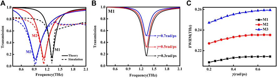
FIGURE 2. (A) Theoretical (solid line) and simulated (dashed line) transmission spectra of M1, M2, and M3, respectively. (B) The line shape of resonant transmission of M1 under different γ. (C) Dependency between FWHM and γ for M1, M2, and M3, respectively.
For the unequal double-bar structures, the impact of the spacing S1 on the spectral properties has been investigated, as shown in Figure 3. In the experiment, when S1 increases from 2 to 24 μm, the low-frequency resonance dip1 presents a red-shift and its slope becomes sharper, while the high-frequency resonance dip2 shows a blue-shift with a broader bandwidth. The transparent window between dip1 and dip2 gradually emerges and exhibits a red-shift. However, if we further increase S1 to 32 μm, the coupling becomes weaker, and the aforementioned changes begin to recover. Figure 3B shows the calculated results of M12 using Eqs 2, 3 based on the bright–bright mode coupling. The fitting parameters under different spacing are listed in Table 1. It is observed that damping rate γ1 decreases significantly but γ2 increases when S1 varies from 2 to 24 μm. Combined with the experimental spectrum, we find that the decreased damping rate corresponds to the increased value of quality factor. The trend of the coupling coefficient κ supports that the coupling strength between two bright modes is essentially enhanced with the increased S1. Notably, S1 of 24 μm results in a uniform distance of all bars in the sample. After further increasing S1, γ1 increases and γ2 decreases, which is consistent with recovery phenomena when S1 is 32 μm. Meanwhile, κ decreases in an obvious manner, which is in good agreement with the weakened coupling, as mentioned previously. It is evident that the strongest coupling occurs at S1 of 24 μm, and it could be attributed to the interaction between the bars in one unit cell and adjacent unit cells.
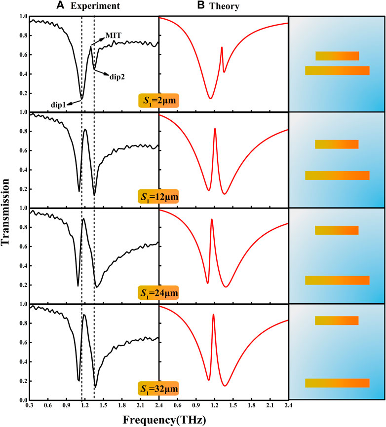
FIGURE 3. Evolution of transmission spectra for M12 with different S1 of 2, 5, 24, and 32 μm, respectively. (A) Experimental transmission spectra. (B) Corresponding theoretical fitting results with the Lorentz oscillator model.

TABLE 1. Parameters used in the coupled Lorentz model for the calculation of M12.
To further study the influence of the parameter on the spectral evolution in the coupled metamaterials, we then vary each parameter while keeping other parameters unchanged. We have modulated the parameters γ1, γ2, and κ, as shown in Figure 4, based on the fitting parameters for S1 of 12 μm. The damping rate represents the radiation loss from the metallic bar and affects the quality factor of the resonance and the MIT magnitude. The coupling coefficient indicates the strength of near-field interaction between the substructures in the metastructure. It is found that, for sample M12, the damping rate mainly determines the FWHM of its resonant dip and the MIT window. As shown in Figure 4A, the FWHM of dip1 increases almost linearly, while the value of MIT window shows an exponential decrease with γ1 from 0.4 to 0.9 rad/ps. Figure 4B also exhibits the similar influence of γ2 on the FWHM of dip2 and the MIT window. It can be seen that κ determines the FWHM of both resonant dips, the MIT window, and the difference in frequency between the two dips (Δf = fdip2-fdip1), as shown in Figures 4C,D. The FWHM of dip1 remains lower than that of dip2, which is consistent with the obtained results in Figure 3A. The FWHM of dip1 shows a linearly decreasing trend and that of dip2 increases exponentially, showing that κ has the opposite influence on the FWHM of two dips. It implies that the stronger coupling leads to the higher (lower) value of quality factor of dip1 (dip2) and more obvious asymmetric spectral line shape. The influence of κ on Δf and the value of MIT window is presented in Figure 4D, with both exponentially increasing behaviors which are in good agreement with the red-shift of dip1 and the blue-shift of dip2 in our experimental data.
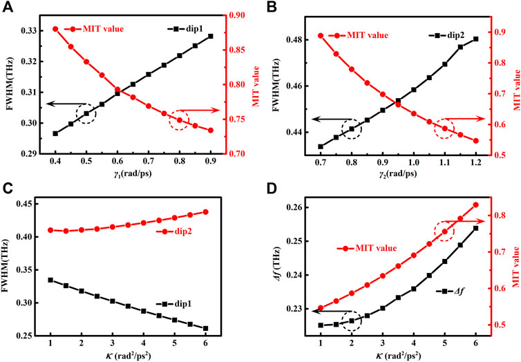
FIGURE 4. (A) Influence of γ1 on the FWHM of dip1 and the value of the MIT window. (B) Influence of γ2 on the FWHM of dip2 and the value of the MIT window. (C) Influence of κ on the FWHM of dip1 and dip2. (D) Influence of κ on Δf and the value of the MIT window.
Similarly, each bar in the M123 structure can individually serve as a bright mode with electric dipole oscillation excited directly by the incident THz wave. By varying the spacing S2 between the bars, the modulations of the transmission properties for the 3-bar sample were observed experimentally, as shown in Figure 5A, with three resonant dips and two MIT peaks. When S2 increases from 2 to 14 μm, dip1 and dip2 present the red-shift, but the former turns into a sharper slope in line shape. Simultaneously, dip3 exhibits an asymmetric line shape with much broader bandwidth. During this process, the values of MIT vary correspondingly, showing the higher value in MIT2 at small S2 and almost the same values in MIT1 and MIT2 at S2 of 14 μm. It can be easily seen that the distance of every 2 bars is uniform in the entire sample for S2 of 14 μm. However, when S2 is further increased to 18 μm, there is no obvious recovery trend, which is totally different from the behaviors in the double-bar structures. Here, dip1 and dip3 have no remarkable difference compared with those for S2 of 14 μm, but the significant changes occur with a blue-shift in dip2 and the lower value of MIT2. This could be attributed to the fact that the couplings between the middle bar M2 and M1 (κ12) or M2 and M3 (κ23) in one unit cell are decreased with the increased bar spacing, while the coupling between M1 and M3 in the adjacent unit cells might affect the spectra. The analytical fitting to the measured amplitude transmission is shown in Figure 5B, which is consistent with the experimental data. The corresponding fitting parameters are listed in Table 2. It is found that for sample M123, damping rate γ1 is nearly invariable with the increasing S2 from 2 to 14 μm, accompanied with a little enhancement in γ2. However, γ3 increases in an obvious manner, suggesting the decreasing quality factor. κ12 and κ23 first increase with S2 and then decrease after further increasing S2 to 18 μm. The coupling weakens if the equidistantly arranged structure is broken. Therefore, the coupling strength can be expected to be modulated via modification of the structural geometry. The simulated results are presented in Figure 5C, showing the consistent spectral evolution behaviors compared with experimental data and theoretical fitting.
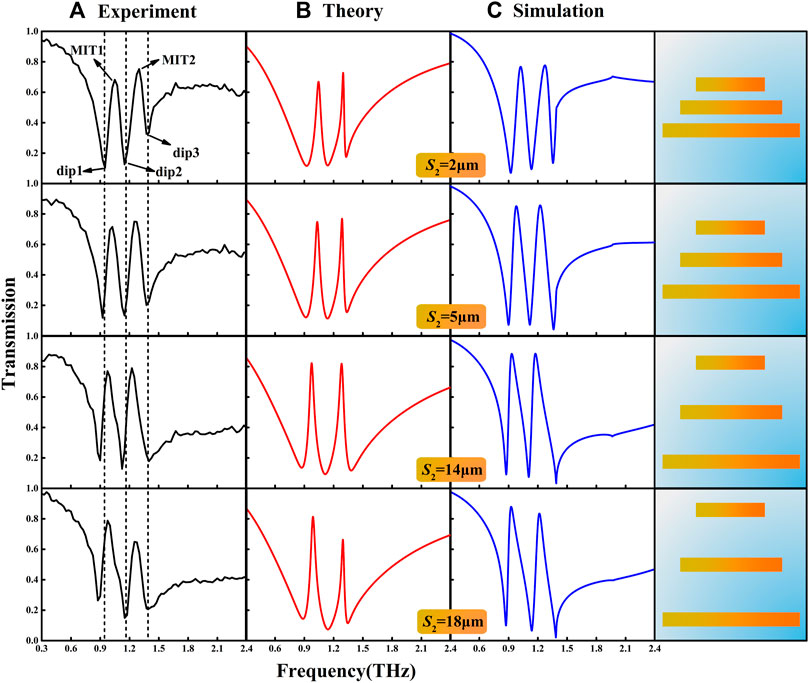
FIGURE 5. Evolution of transmission spectra of sample M123 with S2 of 2, 5, 14, and 18 μm, respectively. (A) Experimental transmission spectra. (B) Corresponding theoretical fitting results with the Lorentz oscillator model. (C) Numerical simulation spectra.
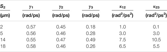
TABLE 2. Parameters used in the coupled Lorentz model for the calculation of M123.
In order to further clarify the underlying coupling mechanism of the 3-bar structures, we have simulated surface current and electric field distributions at resonant dip1, dip2, and dip3, respectively. As shown in Figure 6, the surface currents exhibit the classical dipole resonance with linear current distributed in bars and their edges. The electric fields are mainly localized around bar ends. For instance, at the frequency of dip1 with small bar spacing, we can observe that only M2 and M3 are strongly excited by the incident THz wave with the surface currents out of phase and the overlap of electric field distributions between those 2 bars, suggesting that dip1 is the result of coupling between M2 and M3. Similarly, it is evident that dip2 originates the coupling among 3 bars, and dip3 reveals the coupling between M1 and M2. Gradually, the currents and electric fields present the localized distributions at the top and bottom edge of the unit cell with the increased S2, suggesting the coupling appears between two adjacent unit cells. Here, the distance to another bar in the adjacent unit cell decreases with S2. Moreover, it is interesting that the upper–lower and left–right adjacent couplings can occur in the longest bar M3 by observing the electric field distribution.
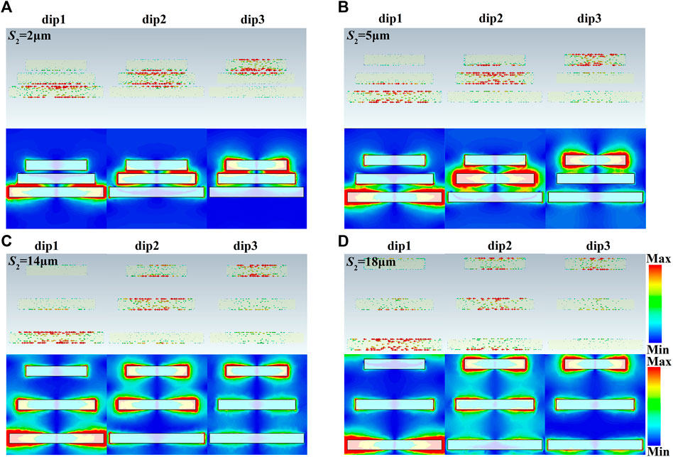
FIGURE 6. Simulated surface currents and electric fields at the frequencies of three dips for S2 of 2 (A), 5 (B), 14 (C), and 18 μm (D), respectively.
Further fitting results are given in Figure 7 to understand the influence of the fitting parameters on the theoretical curve of transmission. We modulate the parameters γi (i = 1,2,3), κ12, and κ23 based on the fitting parameters for S2 of 14 μm. Figure 7A shows the FWHM of dip1 increases, and the value of the MIT1 window shows a distinct decrease when γ1 changes from 0.4 to 0.7 rad/ps. However, γ2 determines the FWHM of dip2, MIT1, and MIT2 windows simultaneously, as shown in Figure 7B. The FWHM of dip2 increases accompanied with an obvious decrease of the value of the MIT1 window and a slight increase of the value of the MIT2 window. It is obvious that γ2 has the greater impact on the value of the MIT1 window than that on the value of the MIT2 window in our studied range. Figure 7C indicates that γ3 mainly affects the FWHM of dip3 and the value of the MIT2 window. The coupling coefficients also affect the FWHM. Because it represents the interaction between two oscillators, the coupling coefficient will simultaneously alter the frequency positions of two resonant dips interacting with each other and the MIT peak located between those two dips. This can have an effect on the symmetry of spectral line shape and make the FWHM increase or decrease with increasing the coupling at different resonant dips. The influence of coupling coefficient on the THz spectral properties is depicted in Figures 7D,E. It is shown that the value of the MIT1 window is enhanced evidently with the increasing κ12, accompanied with the attenuation of the FWHM of dip1 and the slight increase of the FWHM of dip2. Similarly, the value of the MIT2 window increases with κ23, but the FWHMs for both dip2 and dip3 decrease correspondingly. The FWHM of dip3 with a higher value than that of dip2 indicates the lower quality factor, which is in good agreement with the experimental and simulated results. Furthermore, it is noticeable that coupling coefficient also affects the shift of resonant frequency, as shown in Figure 7F, where Δf1 = fdip2-fdip1 and Δf2 = fdip3-fdip2. Although both Δf1 and Δf2 are enhanced with κ12 and κ23, respectively, κ12 has a greater impact on resonant frequency shift than κ23. It is found that a larger frequency shift presents much stronger coupling. In addition to the aforementioned discussion about the resonant dips and MITs, the influence of parameters on the whole spectral lines is presented in Figure 8. The strips of three dips and two MITs are illustrated clearly. It should be noticed that γ1 also affects the MIT2 window slightly, κ12 has an influence on the MIT2 window, and κ23 has an impact on the MIT1 window, as shown in the areas indicated with the dashed lines in Figures 8(A,D,E).
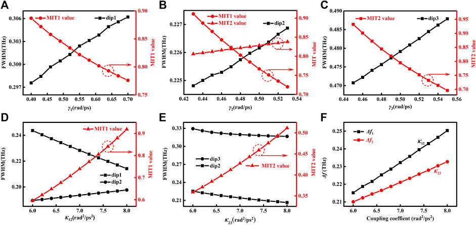
FIGURE 7. (A) Influence of γ1 on the FWHM of dip1 and the value of the MIT1 window. (B) Influence of γ2 on the FWHM of dip2, and the values of MIT1 and MIT2 windows. (C) Influence of γ3 on the FWHM of dip3 and the value of the MIT2 window. (D) Influence of κ12 on the value of the MIT1 window, and the FWHM of dip1 and dip2. (E) Influence of κ23 on the value of the MIT2 window, and the FWHM of dip1 and dip2. (F) Dependency between Δf1 and κ12. Dependency between Δf2 and κ23.
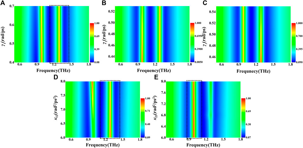
FIGURE 8. Two-dimensional diagrams of the influence of γ1 (A), γ2 (B), γ3 (C), κ12 (D), and κ23 (E) on the transmission spectra.
It is evident that the bar spacing involved with the structure coupling has an impact on the spectral evolution of THz metamaterials with unequal-length bar structures to modulate the resonant dips, the transparency peaks, and the quality factors of the spectra. Hence, those metastructures with different geometrical parameters will possess different spectral sensing properties. We have found that not only the resonant dips but the MIT peaks can also be utilized in analyte sensing. Figure 9 exhibits the simulated frequency shift with the refractive index n of the overlayer on the metamaterial. For metastructure M12, when spacing S1 is 2 μm, Δf at MIT is slightly greater than those at the two other dips. With S1 of 24 μm, Δf increases significantly for MIT and dip1, but the sensing ability of dip2 decreases because the increased coupling results in the Fano-like asymmetric line shape with sharp dip1 and broadening dip2 accompanied with an obvious MIT peak. For metastructure M123 with S2 of 2 μm, three dips and two MIT peaks exhibit the similar frequency shift as the function of n with slightly higher values at MITs. However, at S2 of 14 μm, Δf does not increase and its value of dip3 decreases in an obvious manner, indicating the decreased quality factor and poor sensing performance. It is found that for M12 and M123 samples, although the coupling coefficients increase with spacing, the damping rates, which have a great impact on the FWHM, are different with a most remarkable reduction for dip1 at S1 of 24 μm compared with the values of other dips, suggesting the good sensing ability of dip1 and its accompanied MIT peak in M12. It can be expected that such metastructures can be selected for sensing experiments in the future. Our obtained results indicate that we could explore and optimize the sensing parameters by investigating the evolution of coupled resonances and their sensing properties with the introduction of dielectric overlayers.
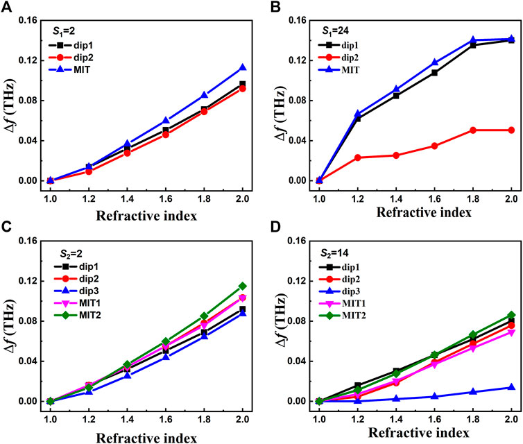
FIGURE 9. Simulated frequency shift with the change of the refractive index of the 100 μm overlayer analyte for metastructures M12 with S1 of 2 (A) and 24 μm (B), and M123 with S2 of 2 (C) and 14 μm (D).
In conclusion, we systematically investigated and analyzed the Lorentz oscillator model from a single resonator to three resonators combined with the experiment and simulation to explore the underlying coupling mechanism, especially the influence of the spacing between bars on the spectral evolution in the double-bar and 3-bar structures. The experimental data exhibit that the resonant dips, the MIT peaks, and the quality factors of the spectra vary with the bar spacing, indicating that not only intracoupling but also intercoupling together play important roles in electromagnetic responses when the spacing between bars is increased. It is noticeable that the spectral evolution with bar spacing in 3-bar structures is different from that in double-bar structures, due to the reason that the middle bar coupling effect is decreased with the other 2 bars’ increased coupling in the M123 sample. Furthermore, the dependences of transmission spectra on the fitting parameters are calculated based on the coupled model. It is found that the damping rate determines the FWHM of its corresponding resonant dip and the MIT peak, which is related to the amplitude of transmission spectra. The coupling coefficient mainly determines the frequency shift and changes the FWHM of its corresponding dip and the MIT window slightly. Further simulated results show that the sensing parameters can be obtained and optimized by investigating the spectral variation of those metastructures after adding the dielectric overlayer. Our research could reveal the mechanism of resonance coupling, clear the role of fitting parameters, help us to design and mimic more complicated coupling mode systems, and establish the foundation to further explore the coupling in THz modulators and sensing devices.
The original contributions presented in the study are included in the article/Supplementary Material; further inquiries can be directed to the corresponding author.
These authors have contributed equally to this work. NJ and ZZ have conducted the calculation; WL has performed the simulation; YD and PZ have carried out the experiment; CZ and QZ are the supervisors.
This study was funded by the National Natural Science Foundation of China (62075142, 61875140), and the Beijing Natural Science Foundation (4181001).
The authors declare that the research was conducted in the absence of any commercial or financial relationships that could be construed as a potential conflict of interest.
All claims expressed in this article are solely those of the authors and do not necessarily represent those of their affiliated organizations, or those of the publisher, the editors, and the reviewers. Any product that may be evaluated in this article, or claim that may be made by its manufacturer, is not guaranteed or endorsed by the publisher.
1. Veselago VG. The Electrodynamics of Substances with Simultaneously Negative Values of $\Epsilon$ and Μ. Sov Phys Usp (1968) 10(4):509–14. doi:10.1070/pu1968v010n04abeh003699
2. Smith DR, Padilla WJ, Vier DC, Nemat-Nasser SC, Schultz S. Composite Medium with Simultaneously Negative Permeability and Permittivity. Phys Rev Lett (2000) 84(18):4184–7. doi:10.1103/physrevlett.84.4184
3. Smith DR, Vier DC, Koschny T, Soukoulis CM. Electromagnetic Parameter Retrieval from Inhomogeneous Metamaterials. Phys Rev E Stat Nonlin Soft Matter Phys (2005) 71(3):036617. doi:10.1103/PhysRevE.71.036617
4. Dolling G, Enkrich C, Wegener M, Soukoulis CM, Linden S. Simultaneous Negative Phase and Group Velocity of Light in a Metamaterial. Science (2006) 312(5775):892–4. doi:10.1126/science.1126021
5. Schurig D, Mock JJ, Justice BJ, Cummer SA, Pendry JB, Starr AF, et al. Metamaterial Electromagnetic Cloak at Microwave Frequencies. Science (2006) 314(5801):977–80. doi:10.1126/science.1133628
6. Dolling G, Wegener M, Soukoulis CM, Linden S. Negative-index Metamaterial at 780 Nm Wavelength. Opt Lett (2007) 32(1):53–5. doi:10.1364/ol.32.000053
7. Cong L, Tan S, Yahiaoui R, Yan F, Zhang W, Singh R. Experimental Demonstration of Ultrasensitive Sensing with Terahertz Metamaterial Absorbers: A Comparison with the Metasurfaces. Appl Phys Lett (2015) 106(3):031107. doi:10.1063/1.4906109
8. Yahiaoui R, Strikwerda AC, Jepsen PU. Terahertz Plasmonic Structure with Enhanced Sensing Capabilities. IEEE Sensors J (2016) 16(8):2484–8. doi:10.1109/jsen.2016.2521708
9. Yahiaoui R, Hanai K, Takano K, Nishida T, Miyamaru F, Nakajima M, et al. Trapping Waves with Terahertz Metamaterial Absorber Based on Isotropic Mie Resonators. Opt Lett (2015) 40(13):3197–200. doi:10.1364/ol.40.003197
10. Yahiaoui R, Ouslimani HH. Broadband Polarization-independent Wide-Angle and Reconfigurable Phase Transition Hybrid Metamaterial Absorber. J Appl Phys (2017) 122(9):093104. doi:10.1063/1.4989933
11. Zhang S, Genov DA, Wang Y, Liu M, Zhang X. Plasmon-induced Transparency in Metamaterials. Phys Rev Lett (2008) 101(4):047401. doi:10.1103/PhysRevLett.101.047401
12. Zhu Z, Yang X, Gu J, Jiang J, Yue W, Tian Z, et al. Broadband Plasmon Induced Transparency in Terahertz Metamaterials. Nanotechnology (2013) 24(21):214003. doi:10.1088/0957-4484/24/21/214003
13. Tassin P, Zhang L, Koschny T, Economou EN, Soukoulis CM. Low-loss Metamaterials Based on Classical Electromagnetically Induced Transparency. Phys Rev Lett (2009) 102(5):053901. doi:10.1103/PhysRevLett.102.053901
14. Liu N, Langguth L, Weiss T, Kästel J, Fleischhauer M, Pfau T, et al. Plasmonic Analogue of Electromagnetically Induced Transparency at the Drude Damping Limit. Nat Mater (2009) 8(9):758–62. doi:10.1038/nmat2495
15. Liu X, Gu J, Singh R, Ma Y, Zhu J, Tian Z, et al. Electromagnetically Induced Transparency in Terahertz Plasmonic Metamaterials via Dual Excitation Pathways of the Dark Mode. Appl Phys Lett (2012) 100(13):131101. doi:10.1063/1.3696306
16. Xu Q, Sandhu S, Povinelli ML, Shakya J, Fan S, Lipson M. Experimental Realization of an On-Chip All-Optical Analogue to Electromagnetically Induced Transparency. Phys Rev Lett (2006) 96(12):123901. doi:10.1103/physrevlett.96.123901
17. Yang X, Yu M, Kwong D-L, Wong CW. All-optical Analog to Electromagnetically Induced Transparency in Multiple Coupled Photonic crystal Cavities. Phys Rev Lett (2009) 102(17):173902. doi:10.1103/physrevlett.102.173902
18. Garrido Alzar CL, Martinez MAG, Nussenzveig P. Classical Analog of Electromagnetically Induced Transparency. Am J Phys (2002) 70(1):37–41. doi:10.1119/1.1412644
19. Singh R, Al-Naib IAI, Koch M, Zhang W. Asymmetric Planar Terahertz Metamaterials. Opt Express (2010) 18(12):13044–50. doi:10.1364/oe.18.013044
20. Kekatpure RD, Barnard ES, Cai W, Brongersma ML. Phase-coupled Plasmon-Induced Transparency. Phys Rev Lett (2010) 104(24):243902. doi:10.1103/physrevlett.104.243902
21. Singh R, Al-Naib IAI, Koch M, Zhang W. Sharp Fano Resonances in THz Metamaterials. Opt Express (2011) 19(7):6312–9. doi:10.1364/oe.19.006312
22. Singh R, Al-Naib IAI, Yang Y, Roy Chowdhury D, Cao W, Rockstuhl C, et al. Observing Metamaterial Induced Transparency in Individual Fano Resonators with Broken Symmetry. Appl Phys Lett (2011) 99(20):201107. doi:10.1063/1.3659494
23. Cao W, Singh R, Al-Naib IAI, He M, Taylor AJ, Zhang W. Low-loss Ultra-high-Q Dark Mode Plasmonic Fano Metamaterials. Opt Lett (2012) 37(16):3366–8. doi:10.1364/ol.37.003366
24. Yu Cao Y, Groves RA, Xuejue Huang XJ, Zamdmer ND, Plouchart J-O, Wachnik RA, et al. Frequency-independent Equivalent-Circuit Model for On-Chip Spiral Inductors. IEEE J Solid-state Circuits (2003) 38:419–26. doi:10.1109/jssc.2002.808285
25. Li C, Chang C-C, Zhou Q, Zhang C, Chen H-T. Resonance Coupling and Polarization Conversion in Terahertz Metasurfaces with Twisted Split-Ring Resonator Pairs. Opt Express (2017) 25(21):25842–52. doi:10.1364/oe.25.025842
26. Su X, Ouyang C, Xu N, Tan S, Gu J, Tian Z, et al. Broadband Terahertz Transparency in a Switchable Metasurface. IEEE Photon J (2015) 7(1):5900108. doi:10.1109/jphot.2015.2390146
27. Yahiaoui R, Burrow JA, Mekonen SM, Sarangan A, Mathews J, Agha I, et al. Electromagnetically Induced Transparency Control in Terahertz Metasurfaces Based on Bright-Bright Mode Coupling. Phys Rev B (2018) 97(15):155403. doi:10.1103/physrevb.97.155403
28. He X, Yang X, Lu G, Yang W, Wu F, Yu Z, et al. Implementation of Selective Controlling Electromagnetically Induced Transparency in Terahertz Graphene Metamaterial. Carbon (2017) 123:668–75. doi:10.1016/j.carbon.2017.08.016
29. Bai Z, Hang C, Huang G. Subluminal and Superluminal Terahertz Radiation in Metamaterials with Electromagnetically Induced Transparency. Opt Express (2013) 21(15):17736–44. doi:10.1364/oe.21.017736
30. Su X, Ouyang C, Xu N, Tan S, Gu J, Tian Z, et al. Dynamic Mode Coupling in Terahertz Metamaterials. Sci Rep (2015) 5:10823. doi:10.1038/srep10823
31. Yan X, Yang M, Zhang Z, Liang L, Wei D, Wang M, et al. The Terahertz Electromagnetically Induced Transparency-like Metamaterials for Sensitive Biosensors in the Detection of Cancer Cells. Biosens Bioelectron (2019) 126:485–92. doi:10.1016/j.bios.2018.11.014
32. Wang Z, Geng Z, Fang W. Exploring Performance of THz Metamaterial Biosensor Based on Flexible Thin-Film. Opt Express (2020) 28(18):26370–84. doi:10.1364/oe.402222
33. Zhang C, Xue T, Zhang J, Liu L, Xie J, Wang G, et al. Terahertz Toroidal Metasurface Biosensor for Sensitive Distinction of Lung Cancer Cells. Nanophotonics (2022) 11(1):101–9. doi:10.1515/nanoph-2021-0520
34. Zhang J, Mu N, Liu L, Xie J, Feng H, Yao J, et al. Highly Sensitive Detection of Malignant Glioma Cells Using Metamaterial-Inspired THz Biosensor Based on Electromagnetically Induced Transparency. Biosens Bioelectron (2021) 185:113241. doi:10.1016/j.bios.2021.113241
35. Hangyo M, Nagashima T, Nashima S. Spectroscopy by Pulsed Terahertz Radiation. Meas Sci Technol (2002) 13(11):1727–38. doi:10.1088/0957-0233/13/11/309
Keywords: coupled resonances, Lorentz oscillator model, terahertz metamaterial, spectral evolution, sensing property
Citation: Jiang N, Zhang Z, Liang W, Deng Y, Zhang P, Zhang C and Zhou Q (2022) Analysis of Evolution of Coupled Lorentz Resonances and Their Sensing Properties in Terahertz Metamaterials. Front. Phys. 10:840090. doi: 10.3389/fphy.2022.840090
Received: 20 December 2021; Accepted: 24 January 2022;
Published: 16 February 2022.
Edited by:
Yuping Yang, Minzu University of China, ChinaReviewed by:
Quan Li, Tianjin University of Technology and Education, ChinaCopyright © 2022 Jiang, Zhang, Liang, Deng, Zhang, Zhang and Zhou. This is an open-access article distributed under the terms of the Creative Commons Attribution License (CC BY). The use, distribution or reproduction in other forums is permitted, provided the original author(s) and the copyright owner(s) are credited and that the original publication in this journal is cited, in accordance with accepted academic practice. No use, distribution or reproduction is permitted which does not comply with these terms.
*Correspondence: Qingli Zhou, cWx6aG91QGNudS5lZHUuY24=
Disclaimer: All claims expressed in this article are solely those of the authors and do not necessarily represent those of their affiliated organizations, or those of the publisher, the editors and the reviewers. Any product that may be evaluated in this article or claim that may be made by its manufacturer is not guaranteed or endorsed by the publisher.
Research integrity at Frontiers
Learn more about the work of our research integrity team to safeguard the quality of each article we publish.