- 1Information Science and Engineering School, Shandong Agricultural University, Taian, China
- 2Shanghai Key Laboratory of Special Artificial Microstructure Materials and Technology, Shanghai, China
- 3Department of Physics, Henan University of Technology, Zhengzhou, China
- 4School of Physics Science and Engineering, Tongji University, Shanghai, China
In this work, micromagnetic simulations demonstrate that a steady oscillation mode accompanied by magnetic domain splitting and the creation and annihilation of meron can be excited by spin-polarized currents. It is found that the in-plane magnetic anisotropy and Dzyaloshinskii-Moriya interaction (DMI) have a greater influence on the oscillation frequency. The oscillation frequency can vary from 3 GHz to 31 GHz by controlling anisotropy strength under a fixed current density. By changing DMI strength, the oscillation frequency varies from 9 to 13.6 GHz and from 29.7 to 37 GHz. Compared with ferromagnetic skyrmion-based spin-torque oscillators (STOs), the STOs based on this magnetic domain and meron further increase the oscillation frequency. Our results may provide theoretical support for the research and development of future high-frequency STOs.
Introduction
Spin orbit torque (SOT) originates from spin orbit coupling (SOC), which can generate spin transfer torque by using the spin flow induced by charge flow [1–6]. According to the different nature of symmetry breaking, SOC effects are classified as Dresselhaus effect [7–9], Rashba effect [10, 11], Edelstein effect [12], and Dzyaloshinskii–Moriya interaction (DMI) [11, 13]. In materials lacking inversion symmetry, DMI comes from chiral exchange interaction caused by the competition between SOC and exchange interaction [11]. Previous experimental studies have shown that magnetic skyrmions can be observed in systems with bulk or interfacial DMI [14–17]. The magnetic skyrmions can be used to generate periodic magnetic oscillation signals which show promise in spin-torque oscillators (STOs) [18–24]. The STOs hold potential applications for next-generation microwave signal generators [25–43], in which the oscillating elements could use different topologically nontrivial spin textures.
A typical stack of the STO is a trilayer structure that consists of two magnetic layers (free layer and fixed polarizer layer) separated by a non-magnetic space layer. From the viewpoint of practical applications, one of the important performance indicators in STO devices is the tunability of oscillation frequency. Intensive efforts have been devoted to manipulating the oscillation frequencies by tuning the external in-plane magnetic field in the ferromagnetic nano contact spin-valve systems [44–48]. The oscillation frequency is up to more than 60 GHz in a uniformly magnetized STO by tuning the in-plane magnetic field [49]. However, for a ferromagnetic skyrmion-based STO, the oscillation frequency usually is only a few GHz. We have reported the frequency changing range of an isolated edge skyrmion-based STO can be generated from 1 to 6.7 GHz [24]. Recent research results show that the oscillation frequency can be improved by adding an annular groove to the free layer of ferromagnetic skyrmion-based STOs [50]. After adding the annular groove, the frequency tunability of the STO can reach ∼16 GHz. In this paper, combined with DMI, a microwave oscillation signal accompanied by magnetic domain splitting is observed in a nano-pillar structure that contains a free layer with an in-plane uniaxial magnetic anisotropy and a spin polarizer with perpendicular magnetic anisotropy. Using micromagnetic simulations, we investigate the changing range of oscillation frequency and the corresponding oscillation mode.
Model and Simulation Details
The STO nanopillar consists of a free layer with in-plane easy-axis anisotropy and a perpendicular polarizer, as illustrated in Figure 1A. The lateral dimension of the nanopillar is 100 nm × 100 nm. The thickness of the free layer tF is 0.5 nm, and the cell size is chosen to be 1 × 1 × 0.5 nm3. Micromagnetic simulations were performed by using the MuMax3 [51]. Time evolution of the free layer magnetization is modeled by the Landau-Lifshitz-Gilbert-Slonczewski (LLGS) equation [25, 51].
where m = M/MS is the local magnetization of the free layer, MS the saturation magnetization, γ is the gyromagnetic ratio, mp is the unit vector of the spin polarizer along the +z direction, and α the Gilbert damping constant. Heff stands for the effective field including the exchange field, anisotropy field, demagnetization field, and interfacial DMI effective field. Note that the thermal fluctuation and the stray field from the polarizer are not taken into account. The third and fourth terms of Eq. 1 describe the damping-like torque and the field-like torque in the spin-transfer torque (STT) effect, respectively. The torque factors are
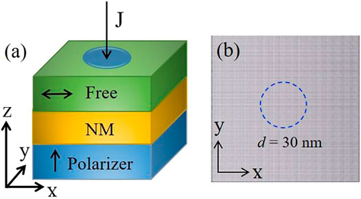
FIGURE 1. (Color online) (A) Schematic diagram of the STO nano-pillar. The free layer has an in-plane magnetic anisotropy. (B) Snapshot of the ground state of the free layer, where the magnetization of the free layer is along the +x direction. Gray is the background color. The central circular region with 30 nm in diameter indicates the regime of applied current.
Results and Discussion
First, we consider the free layer has a ferromagnetic ground state with the magnetization along the +x direction as the initial state at α = 0.5 and DMI = 3.5 mJ/m2, as illustrated in Figure 1B. A negative current is vertically injected into the nano-pillar by a point contact electrode so that the STT generated by the negative current drives the magnetization in the central circular region towards the −z direction (mz < 0, downward direction). However, under the influence of the DMI and in-plane easy-axis magnetic anisotropy, a magnetic domain pair with opposite magnetization orientations begins to appear in the central region at t = 270 ps, as shown in Figure 2A. At t = 310 ps, the central magnetic upward domain (mz > 0) is split up into two distinct magnetic domains. The lower magnetic domain evolves into a meron texture. We calculated the topological number
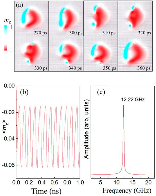
FIGURE 2. (Color online) (A) The spin texture at different times for one oscillation period, where MS = 5.8 × 10⁵ A/m, A = 1.5 × 10⁻¹¹ J/m, K = 8.0 × 10⁵ J/m3, α = 0.5. The current density is 36 × 1011 A/m2. DMI strength is 3.5 mJ/m2 (B) shows the <mz> as a function of time. (C) FFT amplitude spectrum of <mz> in (B).
The oscillation frequency strongly depends on the current density and the material parameters of nano-pillars. Therefore, we firstly investigated the frequency dependence on current density for different damping α, as shown in Figure 3A. Our simulation results indicate that the oscillation mode is similar to that in Figure 2A. In this case, the STT effect becomes stronger with the increased current. This enhanced STT will slow down the downward expansion speed of the left part domain (mz > 0) while the right-part of the domain (mz < 0) maintains its magnetization texture. Consequently, the oscillation period is prolonged. Therefore, the oscillation frequency is negatively correlated with the current density, as shown in Figure 3A. In our simulation work, it should be notated that ε′ is set to 0 in order to make the coefficient of the damping-like torque consistent with those used in other simulation work [50, 54]. In the case of λ = 1, the change of ε′ will change the strength of spin transfer torque effect, which will affect the simulation results. For example, when ε' = 0.2, the coefficient of the damping-like torque will decrease. The oscillation mode can be observed by increasing the current density. When ε' = 0.3, the strength of the field-like torque is greater than that of the damping-like. The precession mode of the magnetization in the central region will be observed.
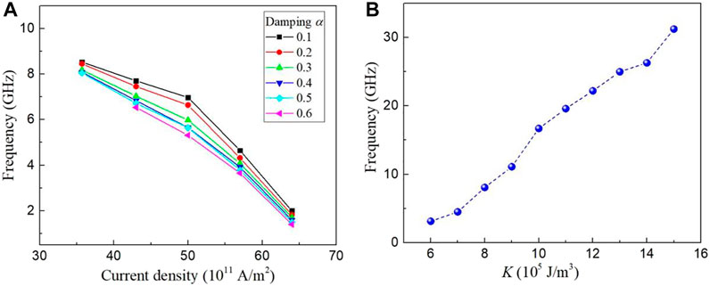
FIGURE 3. (color online) (A) Dependence on the oscillation frequency of the applied current density and the damping α, where MS = 5.8 × 10⁵ A/m, A = 1.5 × 10⁻¹¹ J/m, K = 8.0 × 10⁵ J/m3. DMI strength is 4.0 mJ/m2. (B) Dependence of the oscillation frequency on the anisotropy constant K, where the damping α = 0.5. The current density is fixed to 36 × 1011 A/m2.
The domain pair oscillation results from the competition among spin transfer torque, DMI, and in-plane anisotropy. When the in-plane anisotropy increases, the out-of-plane magnetic moments tend to be in-plane. This will reduce the size of the domain pair, which can shorten the transient time for the left part of the domain to expand downward until it is split. On the other hand, after the splitting of the left domain (mz > 0), the annihilation process of the meron structure at the lower-left region will also be shortened. Therefore, the oscillation frequency is positively correlated with the magnetic anisotropy strengths, as shown in Figure 3B. It is important to note that the oscillation frequency can be tuned from 3 GHz to 31 GHz for different anisotropy strength at a fixed current density. Compared with ferromagnetic skyrmion-based STOs, this magnetic domain and meron-based STO could further increase the range of oscillation frequency.
The DMI strength also has a great influence on the oscillation frequency because the oscillation mode strongly depends on the DMI strength. As shown in Figure 4A, the oscillation frequency increases from 11.9 to 13.6 GHz when the DMI strength increases from 2.0 × 10⁻³ J/m2 to 2.7 × 10⁻³ J/m2. The corresponding oscillation mode is a periodic change process from creation to the splitting of an upward magnetic domain, as shown in Figure 4B. With the DMI strength further increasing to 3.5 × 10⁻³ J/m2, the frequency gradually decreases to 12.17 GHz, and a clear transient meron can be observed in the oscillation mode after the left domain splitting, see Figure 4C. Then the frequency drops to 9.1 GHz and remains around 9 GHz when the DMI strength increases from 3.7 × 10⁻³ J/m2 to 4.5 × 10⁻³ J/m2. As shown in Figure 4D, the corresponding oscillation mode is similar to Figure 4C. However, due to the enhanced DMI strength, the meron creation by the domain splitting process will always exist until a new meron is generated by the next splitting, which compresses the existing meron downward and finally annihilates it. As the DMI strength increases to 4.7 × 10⁻³ J/m2, a stable meron can be observed, as shown in Figure 4E. In this case, the position of the meron is fixed, which can prevent the upward domain from stretching and splitting due to the strong current. Therefore, the upward domain starts to oscillate left and right under the action of the resultant force. This oscillation mode has a shorter period which suddenly increases the frequency to 29.7 GHz for the DMI strength D = 4.7 × 10⁻³ J/m2, as shown in Figure 4A. When the DMI strength increases to 5.0 × 10⁻³ J/m2, the frequency can increase to 37.1 GHz.
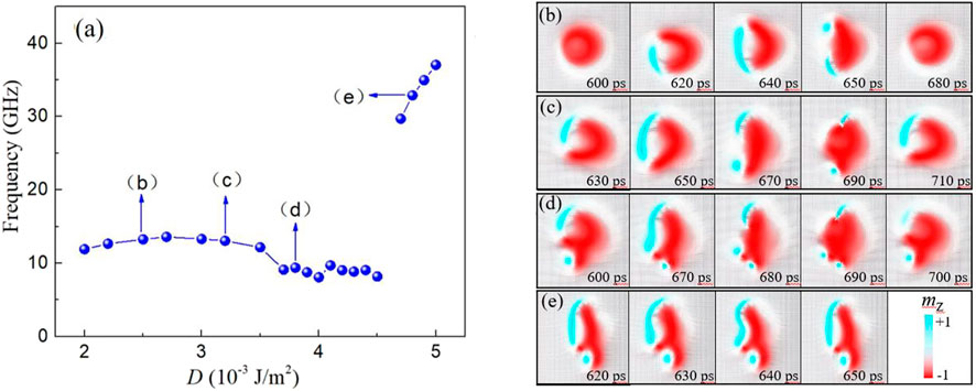
FIGURE 4. (Color online.) (A) Dependence of the oscillation frequency on the DMI strength. The current density is fixed to 36 × 1011 A/m2. (B–E) The time evolution of the magnetization mz for different oscillation modes corresponding to different frequencies marked in (A).
From the above discussion, we can see that the oscillation frequency is related to the magnetic texture, which mainly results from the competition among the spin transfer torque, DMI and in-plane magnetic anisotropy. Since the anisotropy and the DMI strength can affect the oscillation frequency, we guess that the spin polarization direction also effect the oscillation frequency. To verify this idea, we have carried out a series of simulations by changing the orientation of spin polarizer P. From the Figure 5A, we can see that for the case where the polarization deviates from the +z axis and tilts toward +x axis (the easy axis of anisotropy), the oscillation frequency changes a little with θ for θ <
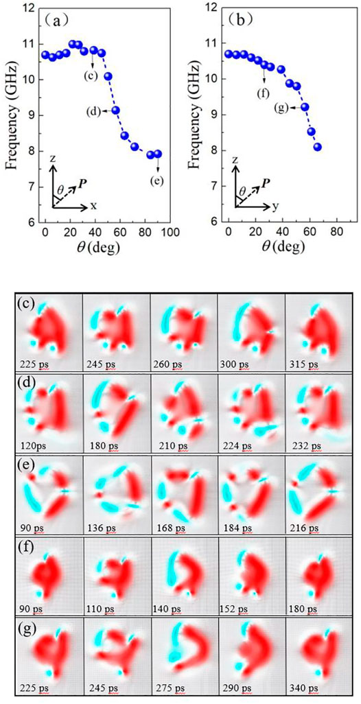
FIGURE 5. (Color online.) (A,B) Dependence on the oscillation frequency of the angle θ between the positive z axis and polarization direction in x-z plane and in y-z plane. The current density is fixed to 36 × 1011 A/m2. (C–G)The time evolution of the magnetization mz for different oscillation modes corresponding to different frequencies marked in (A,B).
In the above simulation results, the diameter d of the central region remains unchanged. However, the previous results show that the amplitude and period of the skyrmion oscillation can be well manipulated by modifying the dimension of the medium [56]. Using the parameters in Figure 2, we study the influence of the diameter d of the central circular region on the oscillation mode. The in-plane dimension of the simulated sample is fixed to 100 nm × 100 nm. The simulation results show that the magnetic mode is different for various d, as shown in Figure 6. When the diameter d is small (d = 15 nm), the magnetization in the central circular region is only tilted at a small angle due to the influence of the edge effect, as shown in Figure 6A. When d increases to 20 nm, a static stable domain pair structure appears, as shown in Figure 6B. For 24 nm < d < 65 nm, the static stable domain pair will evolve into an oscillation mode, as shown in Figure 2A. The oscillation frequency is negatively correlated with d. Once the magnetic upward domain (mz > 0) closes to the left edge of the sample, this domain will be destroyed due to the edge effect. Under the influence of the in-plane anisotropy and DMI, a stable magnetic domain structure is formed, as shown in Figure 6C. It is worth noting that, when the current density increases above a critical value, the stable magnetic domain pair for d = 20 nm can evolve into an oscillating mode. Therefore, in terms of the factors affecting the formation of magnetic oscillation, the small size means large current. However, the increase of oscillation frequency needs to reduce d and current density at the same time.
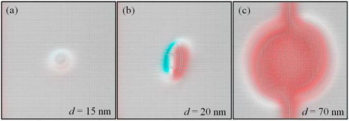
FIGURE 6. (Color online) (A–C) The spin texture for different diameter d, where MS = 5.8 × 10⁵ A/m, A = 1.5 × 10⁻¹¹ J/m, K = 8.0 × 10⁵ J/m3, α = 0.5. The current density is fixed to 36 × 1011 A/m2. DMI strength is 3.5 mJ/m2.
Conclusion
In summary, we proposed an STO concept based on magnetic domain and meron texture in the nanopillar that contains an in-plane magnetized free layer and a perpendicularly magnetized polarizer. Micromagnetic simulations show that a steady oscillation mode with GHz frequencies can be excited by spin currents, accompanied by magnetic domain splitting and the creation and annihilation of the meron state. We investigate the influence of the related parameters including current strength, damping α, anisotropy K, DMI strength, and polarization P on the frequency. The simulation results show that the anisotropy K and DMI strength have a greater influence on the oscillation frequency. The changing range of the frequency is from 3 to 31 GHz for different K under a fixed current. The oscillation frequency varies from 9 to 13.6 GHz and from 29.7 to 37 GHz by changing DMI strength. The current density, damping α and polarization P also affect the frequency, but the effect is relatively small. The changing range of the frequency is only within 10 GHz. Our results also show that the change of frequency is related to the magnetic structure. The variation law of the oscillation frequency will change accordingly when the magnetic structure evolves from one structure to another. The oscillation frequency of nano contact-based STOs observed in the experiment is up to 46 GHz. Theoretically, the observed oscillation frequency is as high as 68 GHz in a spin-torque oscillator that consists of the in-plane magnetized free and pinned layers in the presence of in-plane magnetic field. Therefore, the frequency of the domain-based STOs needs to be further improved. In addition, the frequency tunability, emission power, and line width also need to be improved. In future research work, we will continue to carry out relevant research work in these aspects to further improve the performance of domain-based STOs. Our results may provide theoretical support for the research and development of future high-frequency spin torque nano-oscillators.
Data Availability Statement
The raw data supporting the conclusion of this article will be made available by the authors, without undue reservation.
Author Contributions
GL and HZ performed the micromagnetic simulations. HZ wrote the first draft of the manuscript. XC, FG, GL, and FS participated in the statistics and analysis of the simulations results. ZH established the model used in the simulation. YL gave overall guidance to the manuscript writing. All authors contributed to manuscript revision, read, and approved the submitted version.
Funding
This work was supported by the National Natural Science Foundation of China (NSFC) under the Grant No. 51971161. This work was also supported by the Opening Project of Shanghai Key Laboratory of Special Artificial Microstructure Materials and Technology, and the funding for first-class discipline from Shandong Agricultural University.
Conflict of Interest
The authors declare that the research was conducted in the absence of any commercial or financial relationships that could be construed as a potential conflict of interest.
Publisher’s Note
All claims expressed in this article are solely those of the authors and do not necessarily represent those of their affiliated organizations, or those of the publisher, the editors and the reviewers. Any product that may be evaluated in this article, or claim that may be made by its manufacturer, is not guaranteed or endorsed by the publisher.
Supplementary Material
The Supplementary Material for this article can be found online at: https://www.frontiersin.org/articles/10.3389/fphy.2022.839434/full#supplementary-material
Supplementary Video S1 | The stable oscillation mode based on magnetic domain and meron.
References
1. Miron IM, Garello K, Gaudin G, Zermatten P-J, Costache MV, Auffret S, et al. Perpendicular Switching of a Single Ferromagnetic Layer Induced by In-Plane Current Injection. Nature (2011) 476:189–93. doi:10.1038/nature10309
2. Liu L, Pai C-F, Li Y, Tseng HW, Ralph DC, Buhrman RA Spin-Torque Switching with the Giant Spin Hall Effect of Tantalum. Science (2012) 336:555–8. doi:10.1126/science.1218197
3. Brataas A, Hals KMD Spin-orbit Torques in Action. Nat Nanotech (2014) 9:86–8. doi:10.1038/nnano.2014.8
4. Gambardella P, Miron IM Current-induced Spin-Orbit Torques. Phil Trans R Soc A (2011) 369:3175–97. doi:10.1098/rsta.2010.0336
7. Dresselhaus G Spin-Orbit Coupling Effects in Zinc Blende Structures. Phys Rev (1955) 100:580–6. doi:10.1103/physrev.100.580
8. Manchon A, Koo HC, Nitta J, Frolov SM, Duine RA New Perspectives for Rashba Spin-Orbit Coupling. Nat Mater (2015) 14:871–82. doi:10.1038/nmat4360
9. Winkler R Spin–Orbit Coupling Effects in Two-Dimensional Electron and Hole Systems. Berlin: Springer (2003).
11. Soumyanarayanan A, Reyren N, Fert A, Panagopoulos C Emergent Phenomena Induced by Spin-Orbit Coupling at Surfaces and Interfaces. Nature (2016) 539:509–17. doi:10.1038/nature19820
12. Edelstein VM Spin Polarization of Conduction Electrons Induced by Electric Current in Two-Dimensional Asymmetric Electron Systems. Solid State Commun (1990) 73:233–5. doi:10.1016/0038-1098(90)90963-c
13. Dzyaloshinsky I, Phys J A Thermodynamic Theory of "weak" Ferromagnetism of Antiferromagnetics. J Phys Chem Sol (1958) 4:241–55. doi:10.1016/0022-3697(58)90076-3
14. Nagaosa N, Tokura Y Topological Properties and Dynamics of Magnetic Skyrmions. Nat Nanotech (2013) 8:899–911. doi:10.1038/nnano.2013.243
15. Finocchio G, Büttner F, Tomasello R, Carpentieri M, Kläui M Magnetic Skyrmions: from Fundamental to Applications. J Phys D: Appl Phys (2016) 49:423001. doi:10.1088/0022-3727/49/42/423001
16. Fert A, Reyren N, Cros V Magnetic Skyrmions: Advances in Physics and Potential Applications. Nat Rev Mater (2017) 2:17031. doi:10.1038/natrevmats.2017.31
17. Everschor-Sitte K, Masell J, Reeve RM, Kläui M, Appl J Perspective: Magnetic Skyrmions-Overview of Recent Progress in an Active Research Field. J Appl Phys (2018) 124:240901. doi:10.1063/1.5048972
18. Zhang S, Wang J, Zheng Q, Zhu Q, Liu X, Chen S, et al. Current-induced Magnetic Skyrmions Oscillator. New J Phys (2015) 17:023061. doi:10.1088/1367-2630/17/2/023061
19. Garcia-Sanchez F, Sampaio J, Reyren N, Cros V, Kim J-V A Skyrmion-Based Spin-Torque Nano-Oscillator. New J Phys (2016) 18:075011. doi:10.1088/1367-2630/18/7/075011
20. Jin C, Wang J, Wang W, Song C, Wang J, Xia H, et al. Phys Rev Appl (2018) 9:044007. doi:10.1103/physrevapplied.9.044007
21. Shen L, Xia J, Zhao G, Zhang X, Ezawa M, Tretiakov OA, et al. Spin Torque Nano-Oscillators Based on Antiferromagnetic Skyrmions. Appl Phys Lett (2019) 114:042402. doi:10.1063/1.5080302
22. Zhou Y, Iacocca E, Awad AA, Dumas RK, Zhang FC, Braun HB, et al. Dynamically Stabilized Magnetic Skyrmions. Nat Commun (2015) 6:8193. doi:10.1038/ncomms9193
23. Feng Y, Xia J, Qiu L, Cai X, Shen L, Morvan FJ, et al. A Skyrmion-Based Spin-Torque Nano-Oscillator with Enhanced Edge. J Magnetism Magn Mater (2019) 491:165610. doi:10.1016/j.jmmm.2019.165610
24. Lv G, Zhang H, Jia Z, Gao F, Li G, Sun F, et al. Spin Torque Nano-Oscillators Based on Isolated Edge Skyrmions in Nano-Pillars with Perpendicular Anisotropy. Phys Lett A (2021) 406:127448. doi:10.1016/j.physleta.2021.127448
25. Slonczewski JC, Magn J Current-driven Excitation of Magnetic Multilayers. J Magnetism Magn Mater (1996) 159:L1–L7. doi:10.1016/0304-8853(96)00062-5
26. Berger L Emission of Spin Waves by a Magnetic Multilayer Traversed by a Current. Phys Rev B (1996) 54:9353–8. doi:10.1103/physrevb.54.9353
27. Kaka S, Pufall MR, Rippard WH, Silva TJ, Russek SE, Katine JA Mutual Phase-Locking of Microwave Spin Torque Nano-Oscillators. Nature (2005) 437:389–92. doi:10.1038/nature04035
28. Khvalkovskiy AV, Grollier J, Dussaux A, Zvezdin KA, Cros V Phys Rev B (2009) 80:140401(R). doi:10.1103/physrevb.80.140401
29. Ruotolo A, Cros V, Georges B, Dussaux A, Grollier J, Deranlot C, et al. Phase-locking of Magnetic Vortices Mediated by Antivortices. Nat Nanotech (2009) 4:528–32. doi:10.1038/nnano.2009.143
30. Braganca PM, Gurney BA, Wilson BA, Katine JA, Maat S, Childress JR Nanoscale Magnetic Field Detection Using a Spin Torque Oscillator. Nanotechnology (2010) 21:235202. doi:10.1088/0957-4484/21/23/235202
31. Dussaux A, Georges B, Grollier J, Cros V, Khvalkovskiy AV, Fukushima A, et al. Large Microwave Generation from Current-Driven Magnetic Vortex Oscillators in Magnetic Tunnel Junctions. Nat Commun (2010) 1:8. doi:10.1038/ncomms1006
32. Zeng Z, Finocchio G, Jiang H Spin Transfer Nano-Oscillators. Nanoscale (2013) 5:2219. doi:10.1039/c2nr33407k
33. Hamadeh A, Locatelli N, Naletov VV, Lebrun R, de Loubens G, Grollier J, et al. Origin of Spectral Purity and Tuning Sensitivity in a Spin Transfer Vortex Nano-Oscillator. Phys Rev Lett (2014) 112:257201. doi:10.1103/physrevlett.112.257201
34. Kiselev SI, Sankey JC, Krivorotov IN, Emley NC, Schoelkopf RJ, Buhrman RA, et al. Microwave Oscillations of a Nanomagnet Driven by a Spin-Polarized Current. Nature (2003) 425:380–3. doi:10.1038/nature01967
35. Chung S, Eklund A, Iacocca E, Mohseni SM, Sani SR, Bookman L, et al. Magnetic Droplet Nucleation Boundary in Orthogonal Spin-Torque Nano-Oscillators. Nat Commun (2016) 7:11209. doi:10.1038/ncomms11209
36. Banuazizi SAH, Sani SR, Eklund A, Naiini MM, Mohseni SM, Chung S, et al. Order of Magnitude Improvement of Nano-Contact Spin Torque Nano-Oscillator Performance. Nanoscale (2017) 9:1896–900. doi:10.1039/c6nr07309c
37. Zhang H, Lin W, Mangin S, Zhang Z, Liu Y Signature of Magnetization Dynamics in Spin-Transfer-Driven Nanopillars with Tilted Easy axis. Appl Phys Lett (2013) 102:012411. doi:10.1063/1.4775675
38. Grimaldi E, Dussaux A, Bortolotti P, Grollier J, Pillet G, Fukushima A, et al. Response to Noise of a Vortex Based Spin Transfer Nano-Oscillator. Phys Rev B (2014) 89:104404. doi:10.1103/physrevb.89.104404
40. Kubota H, Yakushiji K, Fukushima A, Tamaru S, Konoto M, Nozaki T, et al. Spin-Torque Oscillator Based on Magnetic Tunnel Junction with a Perpendicularly Magnetized Free Layer and In-Plane Magnetized Polarizer. Appl Phys Express (2013) 6:103003. doi:10.7567/apex.6.103003
41. Houssameddine D, Ebels U, Delaët B, Rodmacq B, Firastrau I, Ponthenier F, et al. Spin-torque Oscillator Using a Perpendicular Polarizer and a Planar Free Layer. Nat Mater (2007) 6:447–53. doi:10.1038/nmat1905
42. Krivorotov IN, Emley NC, Buhrman RA, Ralph DC Phys Rev B (2008) 77:054440. doi:10.1103/physrevb.77.054440
43. Tsunegi S, Yakushiji K, Fukushima A, Yuasa S, Kubota H Microwave Emission Power Exceeding 10 μW in Spin Torque Vortex Oscillator. Appl Phys Lett (2016) 109:252402. doi:10.1063/1.4972305
44. Suzuki H, Endo H, Nakamura T, Tanaka T, Doi M, Hashimoto S, et al. Characteristics of Microwave Oscillations Induced by Spin Transfer Torque in a Ferromagnetic Nanocontact Magnetoresistive Element. J Appl Phys (2009) 105:07D124. doi:10.1063/1.3076047
45. Bonetti S, Muduli P, Mancoff F, Åkerman J Spin Torque Oscillator Frequency versus Magnetic Field Angle: The prospect of Operation beyond 65 GHz. Appl Phys Lett (2009) 94:102507. doi:10.1063/1.3097238
46. Doi M, Endo H, Shirafuji K, Kawasaki S, Sahashi M, Fuke HN, et al. Spin-transfer-induced Microwave Oscillations in Spin Valves with Ferromagnetic Nano-Contacts in Oxide Spacer Layer. J Phys D: Appl Phys (2011) 44:092001. doi:10.1088/0022-3727/44/9/092001
47. Maehara H, Kubota H, Suzuki Y, Seki T, Nishimura K, Nagamine Y, et al. High Q Factor over 3000 Due to Out-Of-Plane Precession in Nano-Contact Spin-Torque Oscillator Based on Magnetic Tunnel Junctions. Appl Phys Express (2014) 7:023003. doi:10.7567/apex.7.023003
49. Arun R, Gopal R, Chandrasekar VK, Lakshmanan M Enhancement of Frequency by Tuning In-Plane Magnetic Field in Spin-Torque Oscillator. J Magnetism Magn Mater (2021) 532:167989. doi:10.1016/j.jmmm.2021.167989
50. Jin C, Ma Y, Song C, Xia H, Wang J, Zhang C, et al. High-frequency Spin Transfer Nano-Oscillator Based on the Motion of Skyrmions in an Annular Groove. New J Phys (2020) 22:033001. doi:10.1088/1367-2630/ab7258
51. Vansteenkiste A, Leliaert J, Dvornik M, Helsen M, Garcia-Sanchez F, Van Waeyenberge B The Design and Verification of MuMax3. AIP Adv (2014) 4:107133. doi:10.1063/1.4899186
52. Sampaio J, Cros V, Rohart S, Thiaville A, Fert A Nucleation, Stability and Current-Induced Motion of Isolated Magnetic Skyrmions in Nanostructures. Nat Nanotech (2013) 8:839–44. doi:10.1038/nnano.2013.210
53. Litzius K, Lemesh I, Krüger B, Bassirian P, Caretta L, Richter K, et al. Skyrmion Hall Effect Revealed by Direct Time-Resolved X-ray Microscopy. Nat Phys (2017) 13:170–5. doi:10.1038/nphys4000
54. Shen L, Li X, Xia J, Qiu L, Zhang X, Tretiakov OA, et al. Dynamics of Ferromagnetic Bimerons Driven by Spin Currents and Magnetic fields. Phys Rev B (2020) 102:104427. doi:10.1103/physrevb.102.104427
55. Shen L, Xia J, Zhang X, Ezawa M, Tretiakov OA, Liu X, et al. Phys Rev Lett (2020) 124:037202. doi:10.1103/physrevlett.124.037202
Keywords: spin-torque oscillator, micromagnetic simulation, domain structure, dzyaloshinskii-moriya interaction, spin orbit coupling
Citation: Lv G, Zhang H, Cao X, Gao F, Li G, Sun F, Hou Z and Liu Y (2022) Spin-Torque Oscillator Based on Magnetic Domain and Meron. Front. Phys. 10:839434. doi: 10.3389/fphy.2022.839434
Received: 20 December 2021; Accepted: 25 January 2022;
Published: 11 February 2022.
Edited by:
Weiwei Lin, Southeast University, ChinaReviewed by:
Yue Zhang, Huazhong University of Science and Technology, ChinaPeng Yan, University of Electronic Science and Technology of China, China
Copyright © 2022 Lv, Zhang, Cao, Gao, Li, Sun, Hou and Liu. This is an open-access article distributed under the terms of the Creative Commons Attribution License (CC BY). The use, distribution or reproduction in other forums is permitted, provided the original author(s) and the copyright owner(s) are credited and that the original publication in this journal is cited, in accordance with accepted academic practice. No use, distribution or reproduction is permitted which does not comply with these terms.
*Correspondence: Hong Zhang, emhhbmdob25nQHNkYXUuZWR1LmNu; Yaowen Liu, eWFvd2VuQHRvbmdqaS5lZHUuY24=
 Gang Lv1,2
 Hong Zhang
 Fengwei Sun
 Yaowen Liu