- 1Department of Physics and Astronomy, University of New Mexico, Albuquerque, NM, United States
- 2Department of Experimental Particle Physics, Jozef Stefan Institute and Department of Physics, University of Ljubljana, Ljubljana, Slovenia
Motivated by the need for fast timing detectors to withstand up to 2 MGy of ionizing dose at the High Luminosity Large Hadron Collider, prototype low gain avalanche detectors (LGADs) have been fabricated in a single pad configuration, 2 × 2 arrays, and related p-i-n diodes, and exposed to Co-60 sources for study. Devices were fabricated with a range of dopant layer concentrations, and for the arrays, a variety of inter-pad distances and distances from the active area to the edge. Measurements of capacitance versus voltage and leakage current versus voltage have been made to compare pre- and post-irradiation characteristics in gain layer depletion voltage, full bulk depletion voltage, and breakdown voltage. Conclusions are drawn regarding the effects of the gammas on both surface and interface states and on their contribution to acceptor removal through non-ionizing energy loss from Compton electrons or photoelectrons. Comparison of the performances of members of the set of devices can be used to optimize gain layer parameters.
Introduction
The low gain avalanche detector (LGAD) [1–3], based on the planar technology, produces a signal in response to the generation of free carriers by a charged particle or high-energy photon; when operated, it is depleted by a reverse bias. An evolution of the avalanche photodiode (APD), the LGAD exhibits internal signal gain in the range of up to 100 that is proportional to the applied bias voltage. The profile of the LGAD structure is n+/p/p−/p+, where the p-implant below the highly doped n+ cathode electrode is referred to as the multiplication implant, forming a gain layer, and has dopant concentration in the range a few times 1016 cm−3 and depth 0.8–2.5 μm. The detection of sub-nanosecond signals produced by minimum ionizing particles is possible with these devices [4].
LGADs are proposed for use in several experiments including upgrades to those at the Large Hadron Collider (LHC) [5, 6]. A typical specification for their operation at the LHC, as components of the High-Granularity Timing Detector (HGTD) in ATLAS or the Endcap Timing Layer (ETL) of CMS, includes tolerance to 2 MGy of the ionizing dose, which will accompany integrated hadron fluence up to about 2.5 × 10¹⁵ neq/cm2 (this includes a safety factor of 1.5). Thin bulk is preferred, as the minimization of induced current variations due to Landau fluctuations will promote the best timing resolution [7].
An active area of research involves the problem of gain decrease as boron-substituted atoms deactivate in response to radiation damage; this is “acceptor removal” [8]. While the primary source of this problem is non-ionizing energy loss (NIEL) due to hadron radiation, a contribution also arises from the associated gammas, which produce point defects in the gain layer through the Compton (and to a lesser extent, photoelectric effect) electrons that they induce.
Gamma radiation motivates a second line of inquiry as well: characterization of oxide charge and interface traps in order to permit optimization of dimensions of the surface features, including interelectrode separation and the distance between the active area and the edge. The goal is to maximize fill factor while ensuring against electrical breakdown under various operating scenarios.
Description of the Prototypes
Prototypes of three structures were produced by Hamamatsu Photonics K.K. (HPK) using epitaxial silicon grown on a Czochralski substrate; these are single LGADs, 2 × 2 (“quad”) LGAD arrays, and associated p-i-n diodes. All have 50 μm active layer thickness, 200 μm total thickness, and a single guard ring. The pads have dimensions of 1.3 × 1.3 mm2. The p-type gain layer is approximately 2.5 μm deep and starts very close to the surface. All of the devices include under-bump metallization (UBM). Figure 1 (left) shows the surface of one such device, which also includes an opening for transient-current technique (TCT) stimulation and a probe needle contact pad. The 2 × 2 arrays have the same features as the smaller devices but variations on inter-pad (“IP”) separation (30, 40, 50, and 70 μm) as well as distance from the active area to the edge (300 and 500 μm). Figure 1 (right) shows a quad prototype. The p-i-n diodes have the same geometry as the LGADs but lack the gain layer. As they can tolerate high bias voltage while sustaining relatively little bulk damage, breakdown in the p-i-ns is indicative of breakdown in the bulk, typically at the guard ring where the field lines are focused. The LGADs and quads were produced with four different options on gain layer dopant concentration. Dopant concentrations of only a few percent difference have previously been shown to lead to very large differences in gain [9].
Single LGAD Studies
Measurements
Prototypes were exposed to gammas at the Sandia National Laboratories Gamma Irradiation Facility for total ionizing doses in the range 0.1–2.2 MGy. Measurements of leakage current versus bias voltage (“IV”) and capacitance C versus bias voltage (“CV”) were carried out before and after the exposure. Figure 2 shows sample IV curves for a set of devices from Wafer 31; these represent the unirradiated characteristic as well as the response to doses of 0.1, 0.5, 1.0, and 2.2 MGy. The principal features of the curves are representative of all of the wafers studied, although differences were observed for the different gain layer concentrations, and they are discussed below. Noteworthy among the principal features are 1) the logarithmic rise in leakage current by approximately an order of magnitude during the initial application of bias, due to the surface component; 2) the foot at approximately 52 V, indicating the depletion of the gain layer; 3) increase of current (by approximately a factor of 5) which is moderate compared to the increase close to breakdown, which occurs above 160 V; this increase is an indication of the gain; 4) saturation of the current at the pre-gain layer depletion voltage at 0.1 MGy; and 5) increase of the breakdown voltage, Vbd, with dose, up to about 205 V for the 2.2 MGy sample.
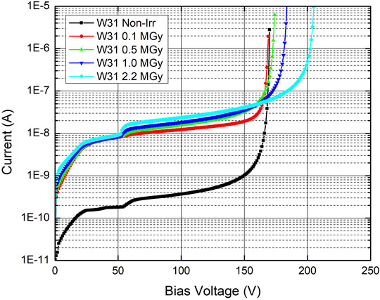
FIGURE 2. Sample current versus voltage characteristics for LGADs from Wafer 31, for various gamma doses.
Figure 3 shows an example curve of 1/C2 versus applied potential V, in this case for an unirradiated LGAD from Wafer 31; data recorded at a temperature of 20°C for applied signal frequency of 1 MHz are shown. The value of the frequency was varied between 1 kHz and 1 MHz, and there was no dependence of the results on the signal frequency provided by the HP4284A LCR meter. The two intercepts of the linear fits to the data in the three regions provide the gain layer depletion voltage Vgl and the full bulk depletion voltage Vfd. Changes in gain layer depletion have previously been shown to correlate with charge collection performance [10].
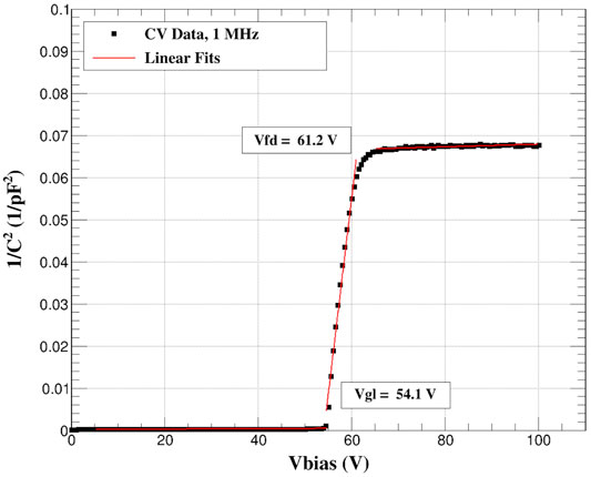
FIGURE 3. Sample capacitance characteristics versus bias voltage, for an unirradiated LGAD from Wafer 31.
Interpretation
Figures 4 and 5 show, respectively, the gain layer depletion voltage Vgl and the difference between the full depletion voltage and Vgl, which should be proportional to the effective dopant concentration, as a function of total ionizing dose, for single LGAD devices representing all of the gain layer dopant concentrations in wafers with UBM. The data in Figure 4 are fit to the function Vgl = Vgl,0 e-cϕ, where ϕ is the total ionizing dose. Table 1 summarizes the extracted acceptor removal constant (c) values for each wafer, following exposure to 2.2 MGy. Also provided there are the pre-irradiation depletion voltages of the gain layers.
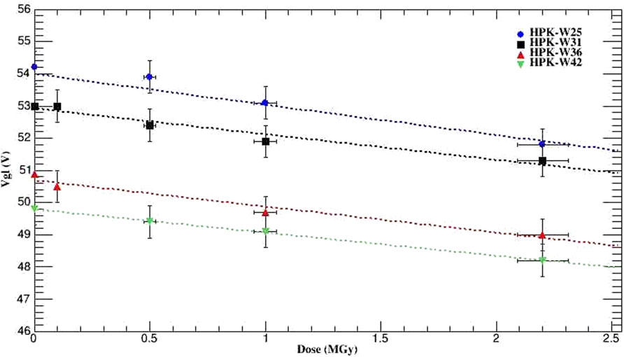
FIGURE 4. Gain layer depletion voltage as a function of dose, for LGADs from all four wafers. The fits to the function Vgl = Vgl,0 e−cϕ are shown, and the resulting values of c are reported in Table 1 as cγ.
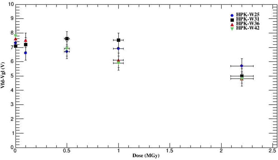
FIGURE 5. Full bulk depletion voltage minus gain layer depletion voltage, as a function of dose, for LGADs from all four wafers.

TABLE 1. Properties of the prototype wafers including the acceptor removal constants cγ of the gain layers, as obtained from a fit of the data in Figure 4 to the formula Vgl = Vgl,0 e−cϕ after the gamma exposure reported here. The initial dopant concentrations of the gain layers (as reflected in the values of Vgl,0) decrease with increasing wafer number.
The Vgl is seen to be only slightly affected by even the highest dose. The full depletion voltage decreases slightly over the same range; this has been observed on epitaxial substrates also for proton-irradiated samples [11]. The observed increase in the breakdown voltage is validated by measurements on the p-i-n diodes (see below). The substantial rise of the surface current below depletion of the gain layer, that is, below the point at which multiplication is possible, can be explained by an increase of the surface recombination velocity. It is not a bulk effect as it does not scale with dose. The fact that it shows signs of saturation above 0.1 MGy is compatible with a surface generation effect. The decrease of Vgl in LGADs implies less multiplication. Once the LGAD is fully depleted, further increase of bias voltage adds to the field which can eventually reach breakdown level. The smaller the gain layer depletion voltage, the larger the breakdown voltage is for the device. For gain layer width approximately 2 microns, and active thickness 50 microns, every decrease of Vgl by 1 V decreases the breakdown voltage by 25 V.
P-I-N Diode Measurements and Interpretation
Figure 6 shows example IV characteristics for p-i-n diodes from Wafer 25, for total ionizing dose from 0 to 2.2 MGy. In this case, post-irradiation breakdown voltages approaching 800 V are achieved, as irradiation-induced oxide charge moderates the electric field. If the LGADs’ primary susceptibility to breakdown were also in the guard ring region, these high values would apply to them as well; however, the LGADs break down at the electrode pads first. These outcomes follow closely the results of measurements made following neutron exposures, reported previously [12]. Between 700 and 800 V, the field in the bulk is sufficiently large that the device breaks down at its weakest point—regardless of whether it is a full LGAD or a p-i-n test structure. For the LGAD, this breakdown is typically through the bulk, whereas for the p-i-n, it is typically at the periphery.
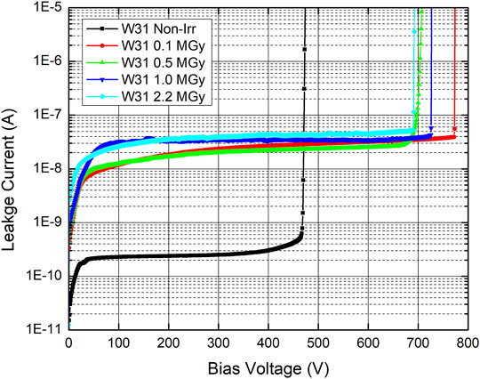
FIGURE 6. Sample current versus voltage characteristics for p-i-n diodes from Wafer 31, for several values of total ionizing dose.
Quad Sensor Measurements and Interpretation
If an electrode is floating, its potential is distributed to neighbors by punch-through [13]. This process places a limit on the interelectrode separation, for which the designer must anticipate the consequences in case a lost bump bond leads to breakdown at an electrode, which could then cascade to breakdowns in neighbors.
An IV study involving the quad sensors was carried out to investigate the question of what minimal interelectrode separation will reliably inhibit full punch-through. Bias is applied to the back side of the chip, and leakage current is measured with ground connected to the guard ring plus 0, 1, 2, 3, or all 4 pads. Figure 7 shows an example set of measurements of this type, for devices taken from Wafer 31, as a function of applied dose.
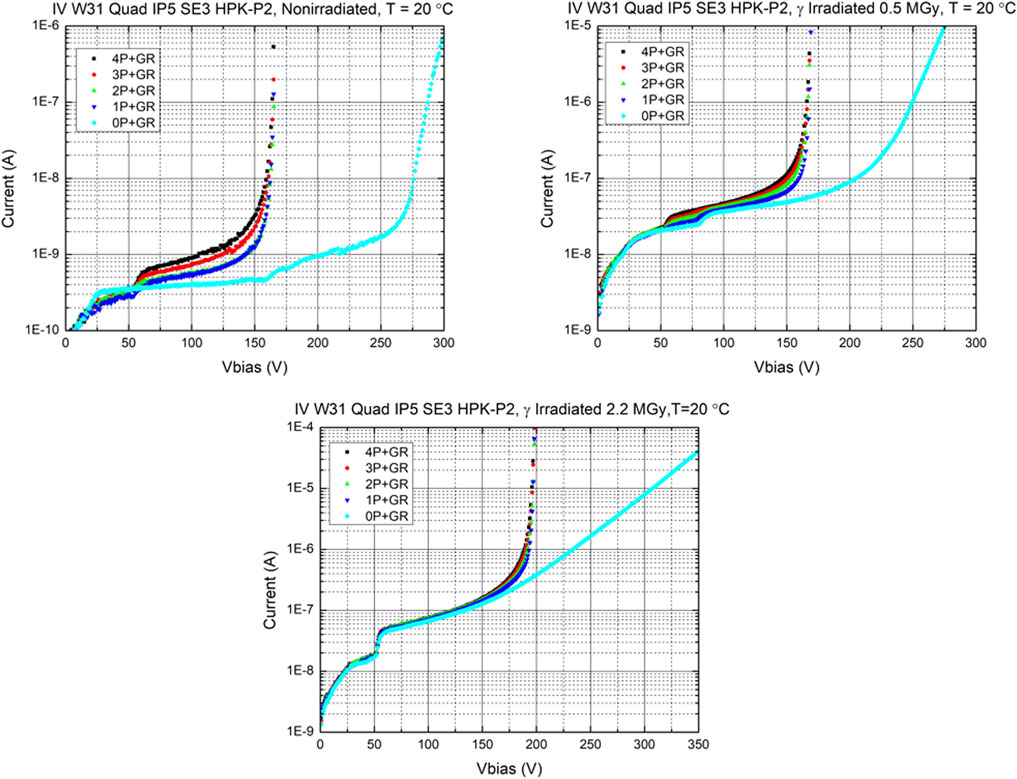
FIGURE 7. Leakage current versus bias voltage for quad sensors taken from Wafer 31, measured (upper left) prior to irradiation, (upper right) after exposure to 0.5 MGy, and (lower) after exposure to 2.2 MGy. In all cases, the temperature during the measurement was 20°C. In each graph, measurements reflect the five modes in which the probes contact the guard ring plus n pads, where n∈{0,1,2,3,4}.
Figure 8 shows the punch-through voltage, as a function of dose, for all four interelectrode separations. Punch-through between the guard ring and the pads occurs around 100–140 V prior to irradiation and decreases to nearly 0 V at 2.2 MGy, indicating the loss of resistivity in the region between the pads and the guard ring. At 2.2 MGy, all of the devices’ IV curves are similar. In the case of the wafer with 30 μm interelectrode separation, the breakdown voltage for measurement on the guard ring alone was observed to be substantially higher than that in the case in which the guard ring plus any non-zero number of pads are contacted. Among wafers with 30 μm interelectrode separation but differing gains, the voltage at which punch-through occurs increases from approximately 85 V in Wafer 25 to approximately 100 V in Wafer 42.
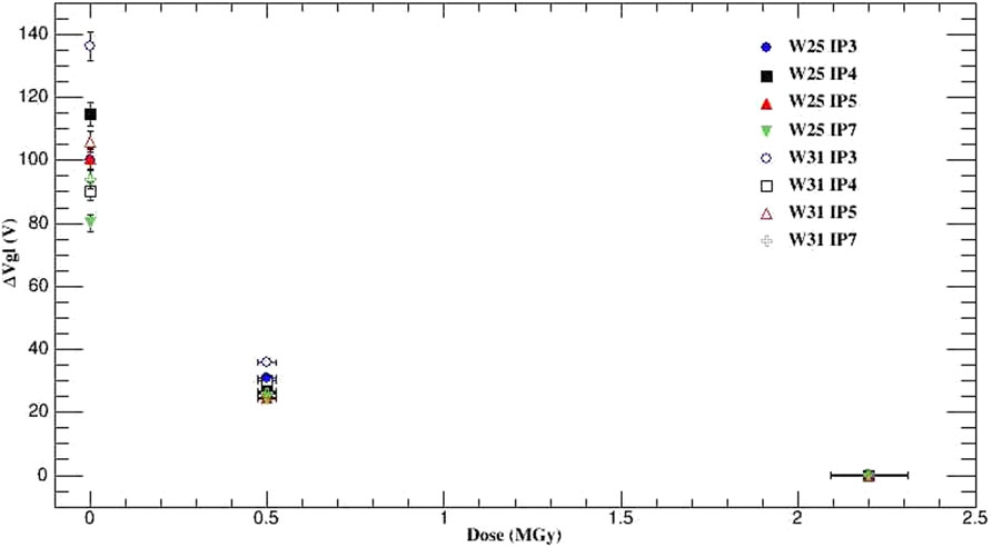
FIGURE 8. The difference between Vgl for the electrodes connected directly to ground, and Vgl for electrodes floating, as a function of dose and interelectrode separation. This indicates the voltage needed for punch-through.
Figure 9 shows the leakage current versus applied bias voltage, for quad devices taken from all wafers (thus with four different initial values of the gain layer depletion voltage). These measurements were made after application of 0.5 MGy, for the measurement configuration indicated above, that is, bias applied to the back side of the chip, and leakage current measured with ground connected to the guard ring plus 0, 1, 2, 3, or all 4 pads. Breakdown occurs at the same bias potential for measurements connecting the guard ring to any number of pads greater than zero. This indicates that the loss of a pad (e.g., disconnection of a bump) will present a danger of breakdown between that pad and its neighbors, for any of the interelectrode separations (30–70 μm) reported here. It is interesting to note that by 2.2 MGy, while the IV curves are identical up to breakdown, the IV measured on the guard ring alone rises with a much slower characteristic.
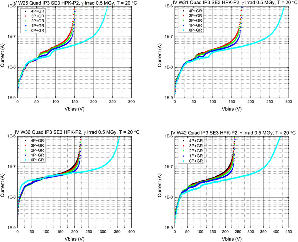
FIGURE 9. Leakage current versus applied bias voltage, for quad devices taken from all wafers (thus with four different initial values of the gain layer depletion voltage). These measurements were made at room temperature after application of 0.5 MGy, for the measurement configuration in which bias is applied to the back side of the chip, and leakage current is measured with ground connected to the guard ring plus 0, 1, 2, 3, or all 4 pads.
The resistance between electrodes in the quad sensors was also measured. On each quad sensor, one pad was biased to values in the range 0.5–2.0 V relative to the remaining three grounded pads, and the current drawn on that biased pad from the others was recorded. The back side of the sensor was biased at −100 V with a separate source meter, and the guard ring was allowed to float. A fit to the slope of this IV characteristic yields the inverse of the resistance. Figure 10 shows the resistance values obtained in this way, for quad sensors representing the four inter-pad spacings, taken from wafers 25 and 31, for doses 0, 0.5, and 2.2 MGy. On all samples, the resistance value is significantly greater than 1 GΩ prior to irradiation; it drops to values around 1 GΩ after application of 0.5 MGy and reaches values in the range 10–100 MΩ after application of 2.2 MGy.
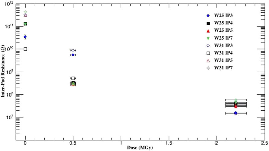
FIGURE 10. Inter-pad resistance measured on wafers 25 and 31, for all four inter-pad spacings, for doses 0, 0.5, and 2.2 MGy.
Uncertainties
The errors on the IV and CV measurements include statistical and systematic uncertainties. Each IV and CV data point shown on the graphs is the average of three to five measurements, and the standard deviation for each is found to be less than 2%. Systematic uncertainties include uncertainties associated with the setup configuration (typically 1.9%), the accuracy of the source and measurement instruments (±0.3% + 100 fA for the Keithley 237; ±0.029% + 300 pA for the Keithley 2410, and ±0.34% for the HP4284A), the precision of the measurement of the temperature (±0.5°C leads to uncertainty of ±1.82% on leakage current), and the data increment size of 1 V. The uncertainties on Vgl, Vfd, and pad resistance are derived from the quality of the linear fits and the bias voltage step size of ±1 V. Analyses of the measurements typically require linear fits, on which the uncertainty is typically a small percent.
Conclusion
The surface, gain layer, and bulk properties of the LGADs included in this study are found to change after gamma irradiation.
For the single LGADs and the p-i-n diodes, the surface component increases the total leakage current by more than an order of magnitude with only 0.1 MGy dose and saturates at about the same level with a high gamma dose. The single LGADs have a much lower breakdown voltage than the p-i-n diodes, indicating that the LGAD breakdown occurs in the bulk at the electrode pad region. Both the gain layer and full depletion voltages decrease by a small amount even at the highest dose, indicating some damage to the gain layer and bulk. The decrease in (Vfd − Vgl) with dose implies a change in doping concentration in the gain layer and thus acceptor removal. The gamma radiation produced Compton electrons and photoelectrons that led to lattice point defects in the gain layer. The acceptor removal constant was characterized by fitting the data to a decaying exponential function (Figure 4), and the resulting values are shown in Table 1.
For the 2 × 2 quad LGADs, the punch-through between the guard ring and the pads for all inter-pad separations has been characterized to be over 100 V prior in irradiation; however, after application of gamma irradiation it decreases for all devices studied and reaches nearly 0 V at the maximum 2.2 MGy dose. Pad-to-pad resistance after the maximum dose is found to lie in the range of 10–100 MΩ. Some variations in punch-through voltage and inter-pad resistance are observed for devices from different wafers and different doping concentrations.
Data Availability Statement
The raw data supporting the conclusions of this article will be made available by the authors, without undue reservation.
Author Contributions
MH, AH, GK, JS, SS, and AY collected and analyzed data. MH and SS carried out irradiations and supervised students’ research. GK supervised students’ research and initiated the device design. SS composed the manuscript.
Funding
This work was made possible by support from the U.S. Department of Energy grant DE-SC0020255 and from ARRS and MIXS, Slovenia. It was also supported by the National Aeronautics and Space Administration (NASA) under Federal award number 80NSSC20M0034.
Conflict of Interest
The authors declare that the research was conducted in the absence of any commercial or financial relationships that could be construed as a potential conflict of interest.
Publisher’s Note
All claims expressed in this article are solely those of the authors and do not necessarily represent those of their affiliated organizations, or those of the publisher, the editors, and the reviewers. Any product that may be evaluated in this article, or claim that may be made by its manufacturer, is not guaranteed or endorsed by the publisher.
Acknowledgments
The opportunity to use the Sandia Gamma Irradiation Facility, made possible by Maryla Wasiolek and Donald Hansen of Sandia National Laboratories, as well as by the University of New Mexico, is gratefully acknowledged. Support from Paulo Oemig of New Mexico State University and the encouragement of Jeremy Perkins and Regina Caputo, both of NASA/GSFC, are deeply appreciated.
References
1. Pellegrini G, Fernández-Martínez P, Baselga M, Fleta C, Flores D, Greco V, et al. Technology Developments and First Measurements of Low Gain Avalanche Detectors (LGAD) for High Energy Physics Applications. Nucl Instr Methods Phys Res Section A: Acc Spectrometers, Detectors Associated Equipment (2014) 765:12–6. doi:10.1016/j.nima.2014.06.008
2. Cartiglia N. Design Optimization of Ultra-fast Silicon Detectors. Nucl Instr Meth A (2015) 796:141.
4. Galloway Z, Fadeyev V, Freeman P, Gkougkousis E, Gee C, Gruey B, et al. Properties of HPK UFSD after neutron irradiation up to 6e15 n/cm2. Nucl Instr Methods Phys Res Section A: Acc Spectrometers, Detectors Associated Equipment (2019) 940:19–29. doi:10.1016/j.nima.2019.05.017
7. Sadrozinski HF-W, Seiden A, Cartiglia N. 4D Tracking with Ultra-fast Silicon Detectors. Rep Prog Phys (2018) 81:026101. doi:10.1088/1361-6633/aa94d3
8. Kramberger G, Baselga M, Cindro V, Fernandez-Martinez P, Flores D, Galloway Z, et al. Radiation Effects in Low Gain Avalanche Detectors after Hadron Irradiations. J Inst (2015) 10:P07006. doi:10.1088/1748-0221/10/07/p07006
9. Moll M, dissertation Ph.D.. Radiation Damage in Silicon Particle Detectors: Microscopic Defects and Macroscopic Properties. Univ. Hamburg (1999).
10. Jin Y, Ren H, Christie S, Galloway Z, Gee C, Labitan C, et al. Experimental Study of Acceptor Removal in UFSD. Nucl Instr Methods Phys Res Section A: Acc Spectrometers, Detectors Associated Equipment (2020) 983:164611. doi:10.1016/j.nima.2020.164611
11. Lindstroem G, et al. Epitaxial Silicon Detectors for Particle Tracking - Radiation Tolerance at Extreme Hadron Fluences. Nucl Instr Meth A (2006) 568:66–71.
12.ATLAS Collaboration. Technical Design Report: A High-Granularity Timing Detector for the ATLAS Phase-II Upgrade. CERN-LHCC-2020-07 (2020).
Keywords: Low Gain Avalanche Detector, LGAD, silicon detector, particle physics, timing detector
Citation: Hoeferkamp M, Howard A, Kramberger G, Seidel S, Sorenson J and Yanez A (2022) Characterization of Low Gain Avalanche Detector Prototypes’ Response to Gamma Radiation. Front. Phys. 10:838463. doi: 10.3389/fphy.2022.838463
Received: 17 December 2021; Accepted: 27 January 2022;
Published: 03 March 2022.
Edited by:
Petra Merkel, Fermilab (DOE), United StatesReviewed by:
Gabriele Giacomini, Brookhaven National Laboratory (DOE), United StatesMarco Mandurrino, National Institute of Nuclear Physics of Turin, Italy
Copyright © 2022 Hoeferkamp, Howard, Kramberger, Seidel, Sorenson and Yanez. This is an open-access article distributed under the terms of the Creative Commons Attribution License (CC BY). The use, distribution or reproduction in other forums is permitted, provided the original author(s) and the copyright owner(s) are credited and that the original publication in this journal is cited, in accordance with accepted academic practice. No use, distribution or reproduction is permitted which does not comply with these terms.
*Correspondence: Sally Seidel, c2VpZGVsQHVubS5lZHU=
 Martin Hoeferkamp
 Alissa Howard2
 Gregor Kramberger
 Sally Seidel