- 1Institute of Advanced Optoelectronic Materials, Technology of School of Big Data and Information Engineering, Guizhou University, Guiyang, China
- 2College of Mathematics and Big Data, Guizhou Education University, Guiyang, China
- 3College of Computer Science and Electronic Engineering, Hunan University, Changsha, China
- 4School of Mechanical and Electrical Engineering, Guizhou Normal University, Guiyang, China
- 5State Key Laboratory of Public Bigdata, Guizhou University, Guiyang, China
A novel, simple Jerk chaotic circuit with three current feedback operational amplifiers included (CFOA-JCC) is proposed, which has a simpler circuit structure, fewer components, but higher frequency characteristics. The dynamic behaviors of CFOA-JCC are analyzed, including equilibrium, stability, Lyapunov exponent, bifurcation diagram, offset boosting, and phase diagram. Furthermore, the frequency spectrum characteristic of the ordinary op-amps Jerk chaotic circuit was compared with CFOA-JCC under the same circuit parameters, and the chaotic attractor frequency of CFOA-JCC can reach about 650 kHz, much better than that of ordinary op-amps (12 kHz). Numerical simulation shows that CFOA-JCC has coexisting attractors, verified by hardware circuit experiments.
Introduction
Chaos is a complex nonlinear phenomenon with special dynamical properties, and various chaotic systems are found and widely used in the fields of electronic communication systems, control systems, and so on [1–6]. Chaotic circuits have become an important tool for studying chaos theory due to easy observation. Proposed by Sprott based on the method of computer exhaustive, the Jerk chaotic system (a class of third-order autonomous chaotic systems) has attracted much attention because it is easy to achieve complex dynamical behavior with a simple structure. The general mathematical expression is
The nonlinear term in the chaotic circuit can be nonlinear functions, piecewise linear functions, and mersister generation [12–14]. However, most Jerk circuit implementations use traditional voltage mode op-amps as active devices, and the gain of the designed circuit must be decreased to increase bandwidth. For the current feedback operational amplifier (CFOA), there is almost no such relationship between gain and bandwidth. Therefore, it is not necessary to design a circuit to balance the gain and bandwidth as a voltage feedback amplifier [15–17]. Therefore, using CFOA to realize chaotic circuits has become a hotspot because CFOA has better frequency gain characteristics [18–24]. It makes the circuit structure simpler and more flexible due to its good port characteristics [25–29]. There have been many reports about the coexistence attractors in recent years, but all the reports did not pay much attention to the simpler topology of the chaotic circuit. For example, in 2011, Sprott proposed a Jerk chaotic circuit with traditional voltage feedback operational amplifiers (VFOA). He did not discuss the coexistence of attractors of his system, and the circuit was not the simplest one. In 2016, Kengene et al. proposed a novel chaotic Jerk circuit, which can realize the coexistence of multiple attractors [30]. Five amplifiers and two diodes had been used in the circuit, and they discussed the frequency of the circuit. In their circuit, the center frequency can be obtained at about 4 Hz. In 2020, Xu et al. proposed a memristive Chua’s circuit with attractors with two stable foci [14]. A one-dimensional multi-scroll chaotic circuit is designed with CFOA [26], but the circuit structure is complex, and there are many active devices. A grid multi-scroll chaotic circuit is designed using CFOA [27, 28], but more active devices are used with lower operating frequency. Wu proposed a chaotic circuit only using CFOA [29], but the center frequency of the chaotic signal is 250 kHz.
In this article, a novel Jerk chaotic circuit with three CFOAs (called CFOA-JCC) was designed to realize a chaotic system in Description of the CFOA-JCC. In Equilibrium Point Analysis, based on the equation of state of CFOA-JCC, the equilibrium point and the system dissipation are analyzed by solving the dimensionless equation. In Dynamical Behaviors, numerical analysis and description were done using MATLAB R2018b to perform the numerical simulation. Lyapunov exponent spectra and bifurcation diagram are plotted in adjusting the parameter regions to reveal the dynamical behaviors. The occurrence of coexisting attractors at deferent initial conditions is also discussed using phase diagrams and bifurcation. Single parameter-controlled offset boosting for variable
Description of the CFOA-JCC
AD844AN is a typical CFOA with better frequency properties. Its circuit symbol is shown in Figure 1A. Under ideal conditions, the port characteristics of AD844AN are satisfied:
With the current output port, the current state of CFOA is easy to observe. As can be seen from the characteristic curve in Figure 1B, the gain of both op-amps is stable when the frequency is within 100 kHz. AD844AN has a better high-frequency performance than VFOA. The closed-loop bandwidth frequency at −3 dB can be expressed as
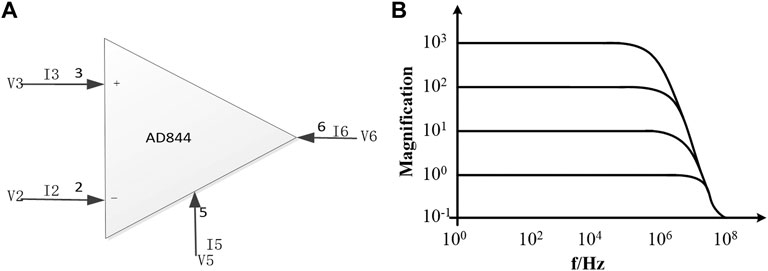
FIGURE 1. AD844AN circuit symbol and its frequency characteristic. (A) AD844AN circuit symbol. (B) Magnification frequency characteristic curve of AD844AN.
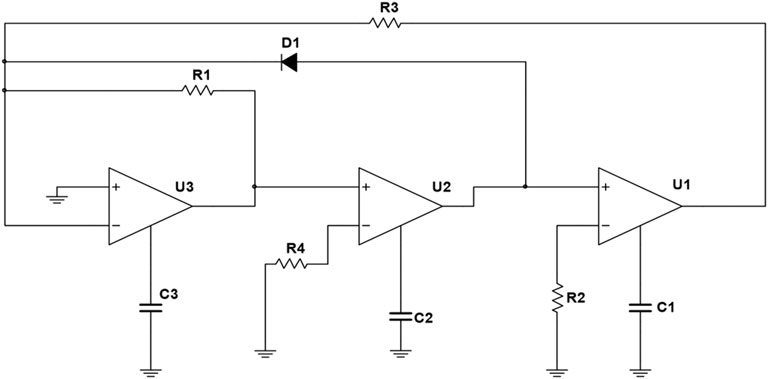
This designed circuit configuration is shown in Figure 2, which includes three CFOAs; three capacitors C1, C2, C3; four resistors R1, R2, R3, R4, and a silicon diode named D1. This circuit is derived from the CFOAs-based sinusoidal oscillator [32], and a nonlinear function is obtained according to volt-ampere characteristics of the diode.
Equilibrium Point Analysis
According to Kirchhoff’s Current Law and Kirchhoff’s Voltage Law, the port characteristics of CFOA, and the current-voltage relations of each circuit component of the novel circuit in Figure 2, in terms of the three-node voltage of u1, u2, u3, three coupled first-order autonomous nonlinear differential equations can be attained to express the nonlinear dynamics of the circuit. The differential equations of the proposed system can be written as
The voltage signals u1, u2, u3 and time variable t are non-dimensional to obtain
When it is at room temperature 300 K, the diode reverse saturation current
Assuming
The Jacobin matrix at the equilibrium point can be derived as
The characteristic equation at the equilibrium is yielded as
The Routh–Hurwitz conditions for the above cubic polynomial Eq. 8 are given by [36–39]
Obviously, the first and second conditions are satisfied in this system, but the third condition is only satisfied when ε and δ take very large values. Then, the system can be stable. Nevertheless, the system is unstable when the value of ε and δ is small, and the above characteristic equation has both positive and negative roots.
The circuit parameters in Figure 2 are given as
Three eigenvalues can be obtained from Eq. 10: λ1 = −1.4665571, λ2 = 0.232786 + 0.792552i, and λ3 = 0.232786 + 0.792552i. Among them, λ2 and λ3 are complex roots, and λ1 is a negative real root. From the three eigenvalues, it can be seen that P0 (0, 0, 0) is an unstable saddle point. Consequently, system (3) may produce chaotic behaviors [40–42]. System (3) is a three-dimensional system, and the divergence of its vector field can be described as
It shows that the system is dissipative. When t→∞, each volume element of the trajectory of the system shrinks to 0 at an exponential rate of −1, and its gradual motion will be fixed on an attractor [43–46].
Dynamical Behaviors
With fixed parameters α = 1, β = 1, γ = 1, δ = 1, and the initial values (x0, y0, z0) = (0, 0.4, 0) and (x0, y0, z0) = (0, −0.4, 0) lying close to the equilibrium point, the Lyapunov exponent (LE) spectrum and bifurcation diagram of the system varying with parameter ε∊ [0.001, 2] can be obtained as shown in Figures 3A,B,D. In this article, all the numerical simulations are made in MATLAB R2018b, the simulation step size is 0.01, the ode45 numerical solver is used, and the simulation time is 500 s.
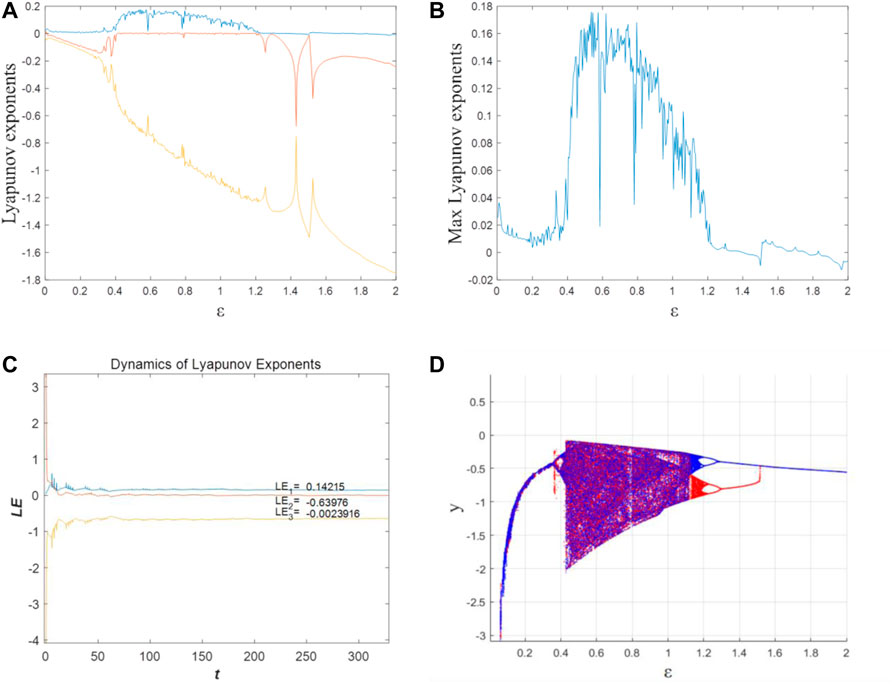
FIGURE 3. Lyapunov exponent spectrum and bifurcation diagram at different initial values. (A) Lyapunov exponents at (x0, y0, z0) = (0, 0.4, 0). (B) Max Lyapunov exponent at (x0, y0, z0) = (0, 0.4, 0). (C) LEs when ε = 0.5 at (x0, y0, z0) = (0, 0.4, 0). (D) Bifurcation diagram at (x0, y0, z0) = (0, 0.4, 0) (red) and (x0, y0, z0) = (0, −0.4, 0) (blue).
The system can maintain a chaotic state when the parameter ε changes within a certain range. The value of the max LE of the system is approximately 0 when ε ∊ [0.001, 0.394), which means the system is in a period state. The bifurcation diagram shown in Figure 3D is represented by one or several curves. When ε ∊ [0.0.39, 0.394), the system produces a bifurcation, which evolves from period 1 to period 2, respectively. When ε ∊ [0.394, 1.2), there is one positive LE, which means the system is in a chaotic state. For instance, as Figure 3C shows, when ε = 0.5, the LEs can be calculated as LE1 = 0.14215, LE2 = −0.63976, LE3 = −0.0023916. LE1 is positive, and LE2 and LE3 are negative, meaning the system’s phase volume is exponentially shrinking. According to the Kaplan–York dimension (
In Figure 3D, the bifurcation diagram also proves the system is chaotic when ε ∊ [0.394, 1.2). With the increase in ε, the system returns to the periodic state when ε ≥ 1.2. From Figure 3D, we also can obtain that there are two different attractors when the initial value is fixed (x0, y0, z0) = (0, 0.4, 0) and (x0, y0, z0) = (0, −0.4, 0). That means there are coexisting attractors in this system.
Figure 4 shows the phase diagram of the system corresponding to different ε values. The process of the system from period bifurcation to chaos and then back to the periodic state can be clearly seen from the diagrams. The trajectories colored in red start from the initial condition (x0, y0, z0) = (0, 0.4, 0) and those colored in blue correspond to (x0, y0, z0) = (0, −0.4, 0). For the two initial conditions, it can be observed from Figure 4 that when ε = 0.5, the chaotic attractor is obtained, as shown in Figures 4A1, A2. Then as ε increases, the system returns to the periodic state, but the period attractors are different under two initial conditions, which are shown in Figures 4B1,B2,C1,C2.
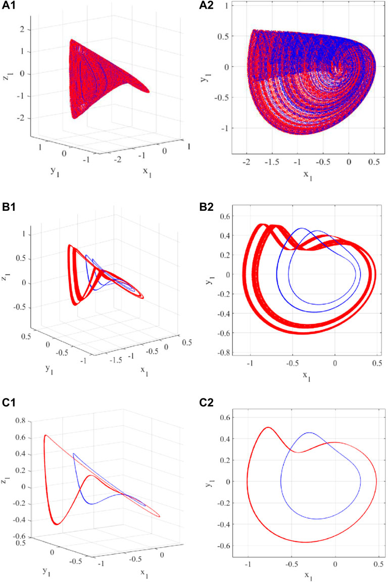
FIGURE 4. The phase diagrams in 3D and 2D (x-y plane) with the initial conditions of (x0, y0, z0) = (0, 0.4, 0) (red) and (x0, y0, z0) = (0, −0.4, 0) (blue), and different values of ε: (A) 0.5; (B) 1.2; (C) 1.3.
The state variable
To better clarify the variable-boostable phenomenon, different k was selected to plot the phase diagrams. For the dimensionless system (13), the fixed time step of 0.001 was used for numerical simulations. The projections of attractors in the x-y plane are given in Figures 5A,B, where the blue, red, and yellow orbits correspond to k = 2 for (x0, y0, z0) = (−2, 0.4, 0), k = 0 for (x0, y0, z0) = (0, 0.4, 0), and k = −2 for (x0, y0, z0) = (2, 0.4, 0). It is found that the attractor is linearly boosted towards the x direction. Besides, we choose a relatively long time interval τ ∊ [1000,5000] to compute the average and amplitude of each variable [49–51]. The average and amplitude (maximum and minimum size) of x, y, and z are plotted in Figures 5C,D, respectively. The results show that both the average and amplitude of the variable x are boosted when adjusting k, whereas the other three variables almost keep unchanging.
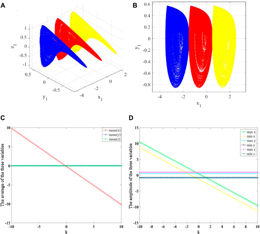
FIGURE 5. Offset boosting behaviors of the system (13) for the constant k. (A) 3D phase diagram of the boosted attractors for k = 2 (blue), k = 0 (red), k = −2 (yellow). (B) x-y plane phase diagrams of the boosted attractors for k = 2 (blue), k = 0 (red), k = −2 (yellow). (C) The average of each variable x, y, and z. (D) the amplitude of variables x, y, and z.
Circuit Implementation and Spectrum Characteristics
Circuit Implementation
To verify the authenticity of the simulation results, the real circuit was made to physically implement the system shown in Figures 6A,B, in which one precision potentiometer, three monolithic ceramic capacitors, one silicon diode 1N4148, three carbon film resistors with the error of ±5%, and three CFOAs AD844AN with operating voltages of ±12 V are utilized. The circuit parameters are listed in Table 1. The experiment results of x-y plane phase diagrams and spectrum can be captured by the UNI-T UTD2102CM and UNI-T UPO9504Z, respectively.

FIGURE 6. Actual circuit implementation with COFAs. (A) Etched circuit board. (B) Actual experimental test with UNI-TUTD2102CM and UNI-T UPO9504Z.
According to the previous normalization formula Eq. 4, when the component parameters in the circuit are fixed, the value of ε depends on R1. When R1 = 34.48 kΩ, the value of ε is 0.29, and the system is in a period one state. Moreover, the value of R1 continues to decrease when R1 is adjusted to correspond to the value of ε in Figure 4, respectively, and the phase diagrams are captured by UNI-T UTD2102CM as shown in Figure 7. According to the phase diagrams, it is found that when R1 is adjusted to a certain fixed value, the phase diagrams can be consistent with the numerical simulation results. For example, R1 = 19.8 kΩ and ε = 0.5, and its phase diagram is shown in Figure 7C. The system is in a chaotic state and is in the same state in Figure 4A. Meanwhile, it is found that when R1 is in the range of [10.1, 12.58] kΩ, the system shows periods corresponding to another period attractor, which also fully proves that the system has the phenomenon of attractors coexistence, as shown in Figures 7D,F.
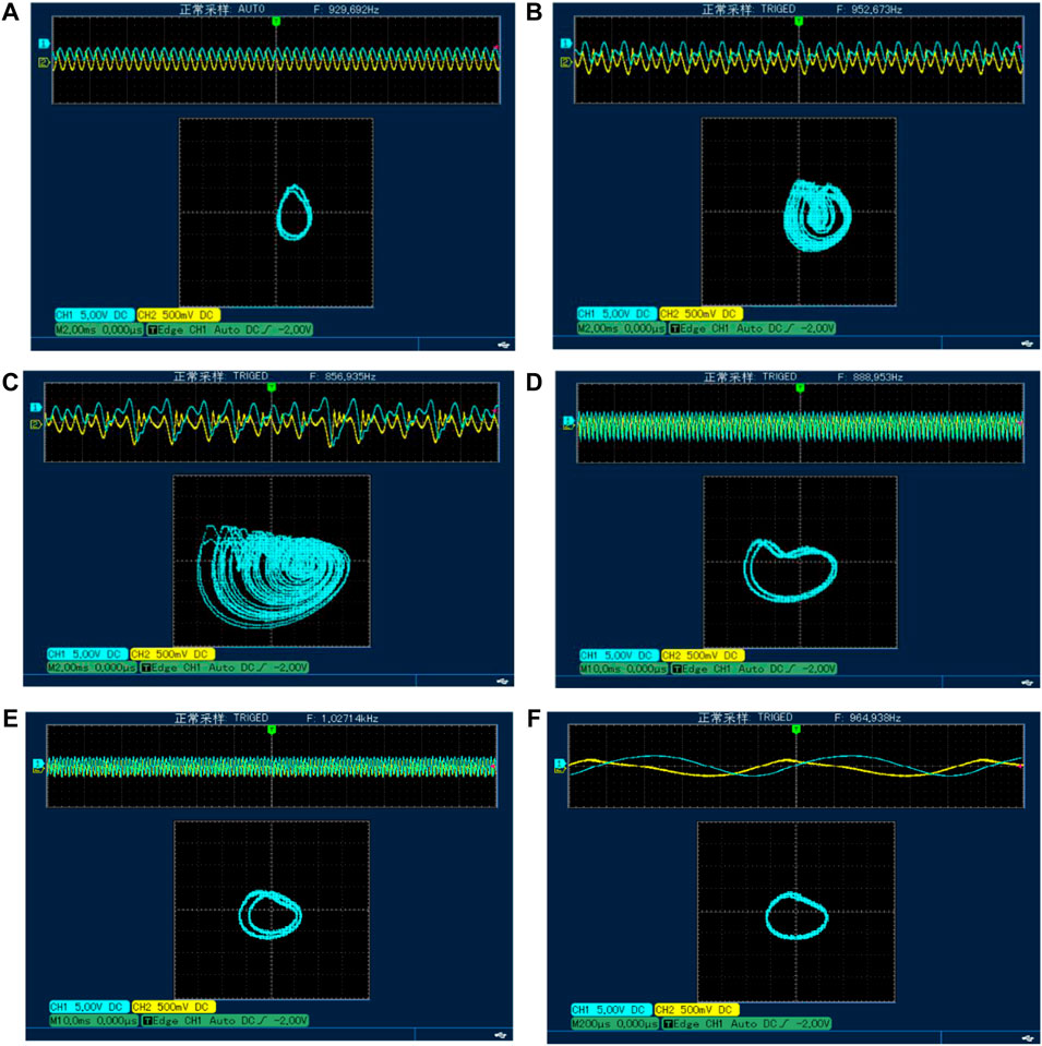
FIGURE 7. Experiment results at different values of R1. (A) R1 = 34.48 kΩ. (B) R1 = 26.35 kΩ. (C) R1 = 19.8 kΩ. (D) R1 = 10.59 kΩ. (E) R1 = 8.32 kΩ. (F) R1 = 7.67 kΩ.
Offset Boosting Implementation
Rewrite Eq. 13 as follows:
According to the circuit diagram of Figure 2 and Eq. 14, the simple Jerk circuit is built in NI Multisim 14.0, as shown in Figure 8A. A circuit in the red dashed box, containing a precision potentiometer, a common discharge constituting a voltage follower, and a resistor forming DC current
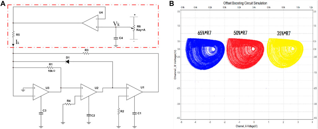
FIGURE 8. The circuit simulation of offset boosting. (A) The circuit of offset boosting for variable x. (B) The attractors of offset boosting when adjusting for R7 to 35% (blue), 50% (red), and 65% (yellow).
To verify the implementation ability of the simulation, we performed the experimental test as shown in Figure 9A. Adjusting the precision potentiometer to correspond the voltage of
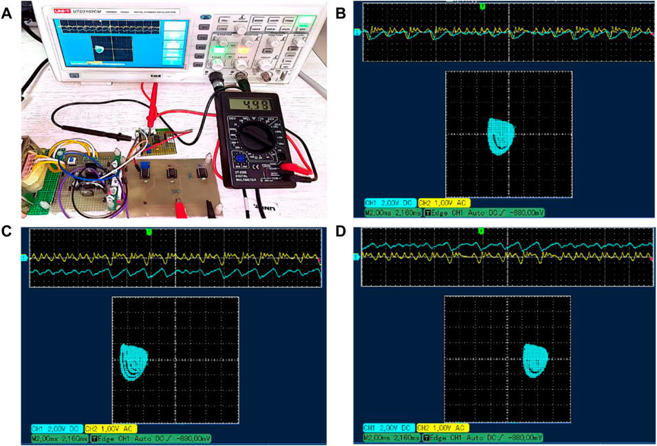
FIGURE 9. Offset boosting with actual circuit implementation and its x-y plane phase diagrams in oscilloscope. (A) Actual experimental test. (B) Vk = −4.5 V. (C) Vk = 0 V. (D) Vk = 4.5 V.
Frequency Spectrum Characteristics
The frequency spectrum is one of the most important characteristics of the chaotic signal. The frequency-domain characteristics of chaos are of great significance in chaotic encryption communication and automatic control [52]. In the integrator circuit, the time constant τ = RC, when R is determined to be unchanged, changing the value of the capacitor C, different time constants can be obtained [53].
For comparison, an experimental circuit using four ordinary op-amps to realize the chaotic system [11] was made as Figure 10 shows which includes four VFOAs AD711AN; three capacitors C1, C2, C3; five resistors R1, R2, R3, R4, R5; one precision potentiometer R6; and one silicon diode D1 1N4148, which provides the nonlinear function.

FIGURE 10. VFOA circuit experimental test. (A) The experimental circuit board with AD711AN. (B) Actual experimental test with UNI-TUTD2102CM and UNI-T UPO9504Z.
The specific parameters are that all the resistances are 10 kΩ in both of the two kinds of the chaotic circuit, and all capacitors are changed according to the experimental requirements at the same time. The frequency spectrums of the chaotic attractor under different time constants are obtained, as shown in Figure 11, during changing the value of integrating capacitors. It can be seen that when C = 100 nF, the center frequency of the two chaotic circuits is about 1.5 kHz. When C = 10 nF, the center frequency is about 12 kHz. Continuously, when C = 1 nF, the circuit with VFOAs is no longer chaotic. It can be seen from the frequency spectrum and the phase diagram that it is in a periodic state. However, CFOA-JCC is still in chaos and the center frequency of the chaotic attractor is about 120 kHz. What is more, the center frequency can be improved to about 650 kHz when C = 200 pF in the CFOA-JCC. Compared with the chaotic circuit based on VFOA, it can generate a high-frequency chaotic signal. Consequently, the CFOA-JCC is not only simple in structure but also can increase the operating frequency of the circuit and broaden its spectrum range.
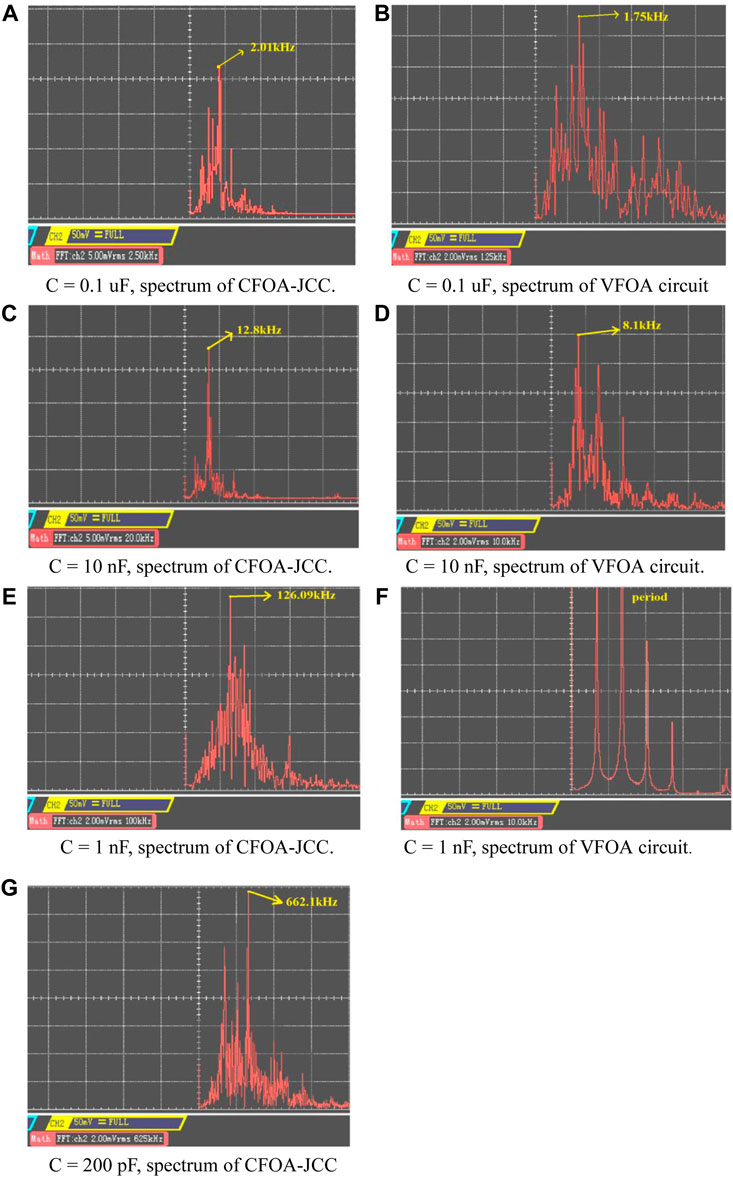
FIGURE 11. Spectrums of the CFOA-JCC and VFOA circuit when capacitors take different values. (A) C = 0.1 uF, spectrum of CFOA-JCC. (B) C = 0.1 uF, spectrum of VFOA circuit. (C) C = 10 nF, spectrum of CFOA-JCC. (D) C = 10 nF, spectrum of VFOA circuit. (E) C = 1 nF, spectrum of CFOA-JCC. (F) C = 1 nF, spectrum of VFOA circuit. (G) C = 200 pF, spectrum of CFOA-JCC
In ideal conditions, the dominant frequency of oscillation is expected to be
Conclusion
The dynamics of CFOA-JCC and the electronic circuit implementation have been discussed extensively in terms of its parameters using standard nonlinear analysis techniques such as bifurcation diagrams, Lyapunov exponent plots, offset boosting, and frequency spectra. The bifurcation analysis suggests that chaos that arises in the CFOA-JCC follows the classical period-doubling when adjusting the bifurcation control parameters slowly. It is also found that the proposed CFOA-JCC exhibits the asymmetrical and striking feature of multiple coexistence attractors for a wide range of circuit parameters. A numerical simulation and circuit experimental test verified the coexistence of multiple attractors of this system. The voltage slew rate of the feedback amplifier is almost independent of frequency and has better high-frequency characteristics. Consequently, the CFOA-JCC has better high-frequency performance than the chaotic circuit designed by ordinary VFOAs, so that higher frequency chaotic attraction can be obtained. At the same time, compared with the VFOA chaotic circuit, the CFOA-JCC has a simpler topology and fewer components, conducive to system integration.
Data Availability Statement
The original contributions presented in the study are included in the article/Supplementary Material. Further inquiries can be directed to the corresponding author.
Author Contributions
QW: system analysis, circuit design, and draft writing. ZT: checking the whole analysis and manuscript revision. XW: numerical analysis, circuit implementation. WT: checking the whole analysis.
Funding
This work was supported by the Natural Science Foundation of China (nos. 51660115, U1612442, 62061008, and 61264004), the Guizhou Province Science and Technology Plan Project (no. 20185769), and Research Projects of Innovation Group of Guizhou Provincial Department of Education (QianJiaoHeKY(2021)022).
Conflict of Interest
The authors declare that the research was conducted in the absence of any commercial or financial relationships that could be construed as a potential conflict of interest.
Publisher’s Note
All claims expressed in this article are solely those of the authors and do not necessarily represent those of their affiliated organizations, or those of the publisher, the editors, and the reviewers. Any product that may be evaluated in this article, or claim that may be made by its manufacturer, is not guaranteed or endorsed by the publisher.
References
1. Lü J., Murali K., Sinha S., Leung H., Aziz-Alaoui M. Generating Multi-Scroll Chaotic Attractors by Thresholding. Phys Lett A (2008) 372(18):3234–9. doi:10.1016/j.physleta.2008.01.065
2. Li Z., Peng C., Tan W., Li L. An Efficient Plaintext-Related Chaotic Image Encryption Scheme Based on Compressive Sensing. Sensors (2021) 21(3):758. doi:10.3390/s21030758
3. Yu F., Zhang Z., Shen H., Huang Y., Cai S., Du S. FPGA Implementation and Image Encryption Application of a New PRNG Based on a Memristive Hopfield Neural Network with a Special Activation Gradient. Chin Phys. B (2021). doi:10.1088/1674-1056/ac3cb2
4. Xu Q., Tan X., Zhu D., Bao H., Bao B. Bifurcations to Bursting and Spiking in the Chay Neuron and Their Validation in a Digital Circuit. Chaos, Solitons & Fractals (2020) 141(927):110353. doi:10.1016/j.chaos.2020.110353
5. Ma C., Mou J., Li P., Liu T. Dynamic Analysis of a New Two-Dimensional Map in Three Forms: Integer-Order, Fractional-Order and Improper Fractional-Order. Eur Phys J Spec Top (2021) 230:1945–57. doi:10.1140/epjs/s11734-021-00133-w
6. Lu T., Chen G., Xing H. Doubling the Coexisting Attractors. Chaos (2019) 29:051102–2. doi:10.1063/1.5097998
8. Sprott J. C. A New Class of Chaotic Circuit. Phys Lett A (2000) 266:19–23. doi:10.1016/s0375-9601(00)00026-8
9. Sprott J. C. Simple Chaotic Systems and Circuits. Am J Phys (2000) 68:758–63. doi:10.1119/1.19538
10. Kiers K., Klein T., Kolb J., Price S., Sprott J. C. Chaos in a Nonlinear Analog Computer. Int J Bifurcation Chaos (2004) 14:2867–73. doi:10.1142/s0218127404010898
11. Sprott J. C. A New Chaotic Jerk Circuit. IEEE Trans Circuits Syst (2011) 58:240–3. doi:10.1109/tcsii.2011.2124490
12. Ma X., Mou J., Liu J., Ma C., Zhao X. A Novel Simple Chaotic Circuit Based on Memristor–Memcapacitor. Nonlinear Dyn (2020) 100:2859–76. doi:10.1007/s11071-020-05601-x
13. Xu Q., Ju Z., Ding S., Feng C., Chen M. Electromagnetic Induction Effects on Electrical Activity within a Memristive Wilson Neuron Model. Cogn Neurodynamics (2021). doi:10.1007/s11571-021-09764-0
14. Xu Q., Lin Y., Bao B., Chen M. Multiple Attractors in a Non-ideal Active Voltage-Controlled Memristor Based Chua's Circuit. Chaos, Solitons & Fractals (2016) 83:186–200. doi:10.1016/j.chaos.2015.12.007
15. Elwakil A. S., Soliman A. M. Current Conveyor Chaos Generators. IEEE Trans Circuits Syst (1999) 46:393–8. doi:10.1109/81.751313
17. Wang C., Zhang J., Wang L., Shi W., Jing D. A Novel Nth-Order Voltage-Mode Universal Filter Based on CMOS CFOA. Optik (2016) 127:2226–30. doi:10.1016/j.ijleo.2015.11.127
18. Kilic R. On Current Feedback Operational Amplifier-Based Realization of Chua's Circuit. Circuits Syst Signal Process (2003) 22:475–91. doi:10.1007/s00034-003-0920-z
19. Kilic R., Yildirim F. Current-Feedback Operational Amplifier-Based Inductorless Mixed-Mode Chua’s Circuits. Int J Bifurcation chaos (2006) 16:709–14. doi:10.1142/S0218127406015076
20. Bao B.-C., Xu J.-P., Liang Y. Inductor Current Sampled Feedback Control of Chaos in Current-Mode Boost Converter. J Electron Sci Technology (2008) 6:52–5.
21. Tan Ping-An T., Zhang Bo Z., Qiu Dong-Yuan Q. Stabilization of Chaotic Behaviour and Spiking Current in Thyristor with Time-Delayed Feedback Control. wlxb (2010) 59:5299–306. doi:10.7498/aps.59.5299
22. Ji X., Ren W., Yuan W. The Design of Multi-Scroll Chaotic Circuit Based on Current Conveyor. Sci Technology Eng (2013) 17.
23. Lin Y., Wang C. H., Xu H. Generation of Grid Multiscroll Chaotic Attractors Using a Current Conveyor. J Math Sci (2014) 201:350–60. doi:10.1007/s10958-014-1995-8
24. Joshi M., Ranjan A. Current-Controlled Chaotic Chua’s Circuit Using CCCII. In: Advances in Communication and Computational Technology. Lecture Notes in Electrical Engineering, 668. Singapore: Springer (2020).
26. Prasad S. R. A New High Frequency Realization of Chua’s Chaotic Circuit Using Current Feedback Operational Amplifiers (CFOA’s). Int J Electron Comput Sci Eng (2012) 1 (02), 223–229.
27. Wand C.-H., Yin J.-W., Lin Y. Design and Realization of Grid Multi-Scroll Chaotic Circuit Based on Current Conveyers. Acta Phys Sin (2012) 61. doi:10.7498/aps.61.210507
28. Lin Y., Wang C. H., Xu H. Grid Multi-Scroll Chaotic Attractors in Hybrid Image Encryption Algorithm Based on Current Conveyor. Acta Physica Sinica (2012) 61:514–8. doi:10.7498/aps.61.240503
29. Wu X. M., He Y. G., Yu W. X. Design and Implementation of Grid Multi-Scroll Chaotic Circuit Based on Current Feedback Operational Amplifier. Acta Physica Sinica (2014) 63. doi:10.7498/aps.63.180506
30. Kengne J., Njitacke Z. T., Nguomkam Negou A., Fouodji Tsostop M., Fotsin H. B. Coexistence of Multiple Attractors and Crisis Route to Chaos in a Novel Chaotic Jerk Circuit. Int J Bifurcation Chaos (2016) 26:1650081. doi:10.1142/s0218127416500814
31. Topaloglu S., Sagbas M., Anday F. Three-input Single-Output Second-Order Filters Using Current-Feedback Amplifiers. AEU - Int J Electronics Commun (2012) 66:683–6. doi:10.1016/j.aeue.2011.12.009
32. Elwakil A. S., Kennedy M. P. Chaotic Oscillators Derived from Sinusoidal Oscillators Based on the Current Feedback Op Amp. Analog Integrated Circuits Signal Process. (2000) 24:239–51. doi:10.1023/a:1008369810214
33. Qiwei T., et al. A Simple Inductor-free Memristive Circuit with Three Line Equilibria. Nonlinear Dyn (2018) 94:1585–602.
34. Se Hwan Kim S. H., Seung Hoon Lee S. H., Jang J. Fabrication and Characterization of Low-Temperature Poly-Silicon Lateral P-I-N Diode. IEEE Electron Device Lett (2010) 31:443–5. doi:10.1109/led.2010.2043047
35. Yan-ning F., Yi-sui S., Ji-lin Z. Non-linear Stability of the Equilibrium of a System of Mass Points. Chin Astron Astrophysics (2002) 26:354–62. doi:10.1016/s0275-1062(02)00077-2
36. Erawaty N., Kasbawati K., Amir A. K. Stability Analysis for Routh-Hurwitz Conditions Using Partial Pivot. J Phys Conf Ser (2019) 1341:062017. doi:10.1088/1742-6596/1341/6/062017
37. Peña J. M. Characterizations and Stable Tests for the Routh-Hurwitz Conditions and for Total Positivity. Linear Algebra its Appl (2004) 393:319–32. doi:10.1016/j.laa.2003.11.013
38. Dharma Rao N. Routh-Hurwitz Conditions and Lyapunov Methods for the Transient-Stability Problem. Proc Inst Electr Eng UK (1969) 116:539–47. doi:10.1049/piee.1969.0112
39. Bottema O. The Routh-Hurwitz Condition for the Biquadratic Equation. Indagationes Mathematicae (Proceedings) (1956) 59:403–6. doi:10.1016/s1385-7258(56)50054-6
41. Lü J., Chen G., Zhang S. Dynamical Analysis of a New Chaotic Attractor. Int J Bifurcation Chaos (2002) 12:1001–15. doi:10.1142/s0218127402004851
42. Marsden J. E., Ratiu T. S. Introduction to Mechanics and Symmetry. New York: Springer-Verlag (1999).
43. Pehlivan İ., Uyaroğlu Y. A New 3D Chaotic System with golden Proportion Equilibria: Analysis and Electronic Circuit Realization. Comput Electr Eng (2012) 38:1777–84. doi:10.1016/j.compeleceng.2012.08.007
44. Teng L., Iu H. H. C., Wang X., Wang X. Chaotic Behavior in Fractional-Order Memristor-Based Simplest Chaotic Circuit Using Fourth Degree Polynomial. Nonlinear Dyn (2014) 77:231–41. doi:10.1007/s11071-014-1286-4
45. Zhang X., Chen M., Wang Y., Tian H., Wang Z. Dynamic Analysis and Degenerate Hopf Bifurcation-Based Feedback Control of a Conservative Chaotic System and its Circuit Simulation. Complexity (2021) 2021:1–15. doi:10.1155/2021/5576353
46. Joshi M., Ranjan A. Investigation of Dynamical Properties in Hysteresis-Based a Simple Chaotic Waveform Generator with Two Stable Equilibrium. Chaos, Solitons & Fractals (2020) 134:109693 doi:10.1016/j.chaos.2020.109693
47. Li C., Sprott J. C., Liu Y., Gu Z., Zhang J. Offset Boosting for Breeding Conditional Symmetry. Int J Bifurcation Chaos (2018) 28(14):1850163. doi:10.1142/s0218127418501638
48. Ma C., Mou J., Xiong L., Banerjee S., Han X. Dynamical Analysis of a New Chaotic System: Asymmetric Multistability, Offset Boosting Control and Circuit Realization. Nonlinear Dyn (2021) 103:1–14. doi:10.1007/s11071-021-06276-8
49. Li C., Lei T., Wang X., Chen G. Dynamics Editing Based on Offset Boosting. Chaos (2020) 30:063124. doi:10.1063/5.0006020
50. Li C., Gu Z., Liu Z., Jafari S., Kapitaniak T. Constructing Chaotic Repellors. Chaos, Solitons & Fractals (2021) 142:110544. doi:10.1016/j.chaos.2020.110544
51. Li C., Peng Y., Tao Z., Sprott J. C., Ja Fari S. Coexisting Infinite Equilibria and Chaos. Int J Bifurcation Chaos (2021) 31. doi:10.1142/s0218127421300147
52. Zemlyanyi O. V. KEYING OF THE BROADBAND CHAOTIC SIGNAL SPECTRUM FOR DATA TRANSMISSION. Telecommunications Radio Eng (2016) 75 (05), 401–411. doi:10.1615/TelecomRadEng.v75.i5.20
Keywords: Jerk, chaotic, coexisting attractors, CFOA, frequency spectrum
Citation: Wang Q, Tian Z, Wu X and Tan W (2022) Coexistence of Multiple Attractors in a Novel Simple Jerk Chaotic Circuit With CFOAs Implementation. Front. Phys. 10:835188. doi: 10.3389/fphy.2022.835188
Received: 14 December 2021; Accepted: 14 January 2022;
Published: 07 February 2022.
Edited by:
Jun Mou, Dalian Polytechnic University, ChinaReviewed by:
Quan Xu, Changzhou University, ChinaChunbiao Li, Nanjing University of Information Science and Technology, China
Copyright © 2022 Wang, Tian, Wu and Tan. This is an open-access article distributed under the terms of the Creative Commons Attribution License (CC BY). The use, distribution or reproduction in other forums is permitted, provided the original author(s) and the copyright owner(s) are credited and that the original publication in this journal is cited, in accordance with accepted academic practice. No use, distribution or reproduction is permitted which does not comply with these terms.
*Correspondence: Zean Tian, dGlhbnplYW5AaG51LmVkdS5jbg==
 Qiao Wang
 Zean Tian1,3*
 Xianming Wu
 Weijie Tan