ORIGINAL RESEARCH article

Front. Phys., 03 February 2022
Sec. Optics and Photonics
This article is part of the Research Topic Topological Photonics View all 15 articles

Bidirectional Rainbow Trapping in 1-D Chirped Topological Photonic Crystal

  • 1Key Laboratory of Advanced Optoelectronic Quantum Architecture and Measurements of Ministry of Education, Beijing Key Laboratory of Nanophotonics and Ultrafine Optoelectronic Systems, School of Physics, Beijing Institute of Technology, Beijing, China
  • 2Physics Department, Faculty of Science, Assiut University, Assiut, Egypt
  • 3Collaborative Innovation Center of Light Manipulations and Applications, Shandong Normal University, Jinan, China

The rainbow trapping effect has attracted gathering attention due to its potential application in data processing, energy storage, and light-matter interaction enhancement. The interest has increased recently with the advent of topological photonic crystals (PCs), as the topological PC affords a robust platform for nanophotonic devices. We proposed a chirped one-dimensional (1D) PC as a sandwiched trapped between two1D topological PCs to realize two topological edge states (TESs) for topological protection and trap the formed rainbow. Through graded the thickness of dielectric layers of the chirped 1D PC, light of different wavelengths components localizes and stores at different spatial positions leading to rainbow trapping formation. Unidirectional rainbow trapping can be observed by progressively increasing the thicknesses of the chirped PC. Nonetheless, changing increasingly one of its thicknesses and solidifying the other leads to bidirectional rainbow trapping. Achieving bidirectional rainbow trapping will reduce the footprint of nanophotonic devices in the future. This work brings inspiration to the realization of the rainbow trapping effect and provides a way to design topological nanophotonic devices.

Introduction

Photonics is principally concerned with the wave properties of frequency, wavevector, and polarization, representing the degrees of freedom of essential information for any optical system. Frequency plays an instrumental part in integrated photonic devices. In particular, it has been shown that in a tapered metamaterial structure, light can be trapped and slowed down in exact positions depending on its frequency [1]. This phenomenon is named a trapped rainbow, just as sunlight is scattered in a continuous color spectrum through a prism (hence the name is rainbow). The effect can also be considered as the spatial separation of the frequency components of the propagating wave. The appearance of rainbow trapping offers a novel technique for frequency routing of slow light [1]. After the formation of the first theoretical work, many successive methods were presented to realize rainbow trapping, such as metamaterials [1, 2], metasurfaces [3], plasmonic structures [46], phononic crystals in one-dimensional (1D) [7] and two-dimensional (2D) [8], and photonic crystals (PCs), in 1D [9], 2D [10, 11] and three-dimensional (3D) [12]. Most of the mentioned methods depend on either metallic or dielectric materials. However, metallic materials are lossy at optical wavelengths. Thus, the fully dielectric structure (PCs) is an excellent alternative to realizing rainbow trapping.

The rainbow trapping effect has attracted attention due to its potential applications in data processing, energy storage, and light-matter interaction enhancement. The interest has increased recently with the advent of topological PCs, which affords a robust platform for optical devices. Consequently, the combination of topology and rainbow can make possible new potentials designing topologically protected photonic devices. Due to the complex design and manufacturing structure of 2D and 3D PCs, topological PCs are preferred in the 1D structure for the advantages of simple design and ease of fabrication.

In this paper, the proposed structure is based on two-1D topological PCs to realize two topological edge states (TESs) for topological protection and trap the formed rainbow. A chirped 1D PC is inserted as a sandwiched between the two-1D topological PCs. The way to achieve the rainbow is to set the structure (or chirp) statically through one or more basic structural parameters such as position, size, and refractive index that gradually change along the direction of propagation. Through graded the thickness of dielectric layers of the chirped 1D PC, light of different wavelengths components localizes and stores at different spatial positions leading to rainbow trapping formation. The interesting observation is bidirectional rainbow trapping, increasing the thickness of one layer kind progressively and solidifying a different kind. Thus, the light propagates and localizes in both directions in the trapped area between the two TESs. Then, different frequencies can be segregated at different positions in both directions. To the best of our knowledge, this type of rainbow trapping has not been observed in topological photonics. Achieving bidirectional rainbow trapping will reduce the footprint of the nanophotonic device in the future. It is possible for this type of rainbow trapping to have numerous applications, for example, a bidirectional optical filter, a bidirectional laser, etc.

Designs and Results

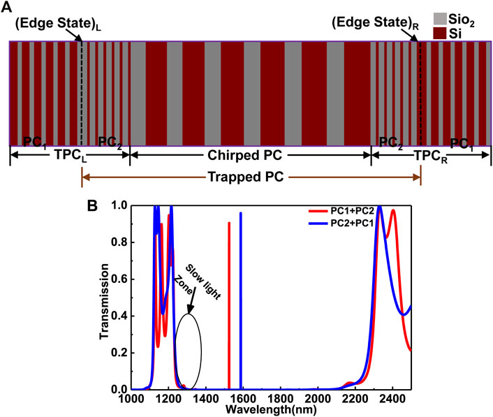
The topological heterostructure of PC is based on two topological PCs, namely TPCL and TPCR as shown in Figure 1A. TPCL is composed of two PCs (PC1 and PC2), from the same dielectric materials of silicon Si and silicon dioxide SiO2 with refractive indices nSi=3.48 and nSiO2=1.45, respectively. TPCR, is composed of two PCs (PC2 and PC1), is the mirror image of TPCL. PC1 consists of six consecutive layers from Si and SiO2 of layer thicknesses d1Si=350nm, and d1SiO2=225nm, respectively, and the lattice constant of PC1 is a1=575nm. The thicknesses of PC2, are evaluated based on [13], are d2SiO2=276nm and d2Si=115nm and consists of six consecutive layers from SiO2 and Si, respectively with a2=391nm. The TESs can exist in TPCL(PC1+PC2) and TPCR(PC2+PC1) at the heterostructure interface because the two PCs possess bandgaps in the same wavelength range with different topological properties [14]. The transmission spectrum of TPCL and TPCR is shown in Figure 1B using the finite element method (FEM), solver package of COMSOL Multiphysics, with perfect matched layer boundary condition (PML). Two TESs formed at the left and right interfaces with a high resonated transmission peak between the two stacked PCs. The two TESs areas appeared inside the bandgap, allowing two areas of slow light zones near the bandgap edges. Whereas the two edge states work as a topological cavity to trap the light inside the chirped structure, which may enhance the field localization and quality factor.

FIGURE 1
www.frontiersin.org

FIGURE 1. (A) Schematic diagram of 1D PC heterostructure; (B) the transmission spectrum of TPCL andTPCR.

A linearly chirped 1D PC is inserted as a sandwiched between the two-1D topological PCs. The chirped 1D PC is composed of six consecutive layers from SiO2 and Si. It started from SiO2 to avoid the edge states between PC2 and the chirped one. Consequently, PC2, chirped PC and PC2 formed a trapped PC, and the formed rainbow trapping will be topologically protected by the two TESs as shown in Figure 1A. The possibility for the light entering the trapped PC to escape is slight because the two edge states work like topological cavities. The thicknesses of SiO2 and Si layers are dSiO2 and dSi respectively. Through graded dSiO2 linearly from 740 to 765 nm and dSi from 1,000 nm to 1,100 nm, the light can be trapped and slowed down in exact position depending on its frequency, forming a rainbow trapping effect.

Unidirectional and Bidirectional Rainbow Trapping

As mentioned above, achieving rainbow trapping is to set the structure statically through one or more basic structural parameters that gradually change along the propagation direction. Unidirectional rainbow trapping can be observed by gradually increasing dSiO2 and dSi of the chirped PC sandwiched between the two topological PCs. dSiO2 is varying from 740 to 765 nm with an increment of 5 nm and dSi from 1,000 to 1,100 nm with an increment of 20 nm. Figure 2A shows the transmission spectrum of the proposed structure with the fitting curves, which are symmetric in the representative Lorentzian-line shape. The resonated transmission peaks at nm wavelengths are 1234.91,  1251.16,  1268.82,  1294.75,  and 1328.50, with the full width at half maximum (FWHM) by nm is 1.41444,  0.23029,  0.05598,  0.01136,   and 5.86×10⁴  respectively. The quality factor (Q), which is the ratio of the resonant wavelength to FWHM, at each resonated transmission peak is 873.07,  5.43×10³,  2.26×10⁴,  1.13×10⁵,  and 2.26×10⁶  respectively. The high Q-factor due to the robust field localization between the two TES, which led to robust optical localization in the chirped area.
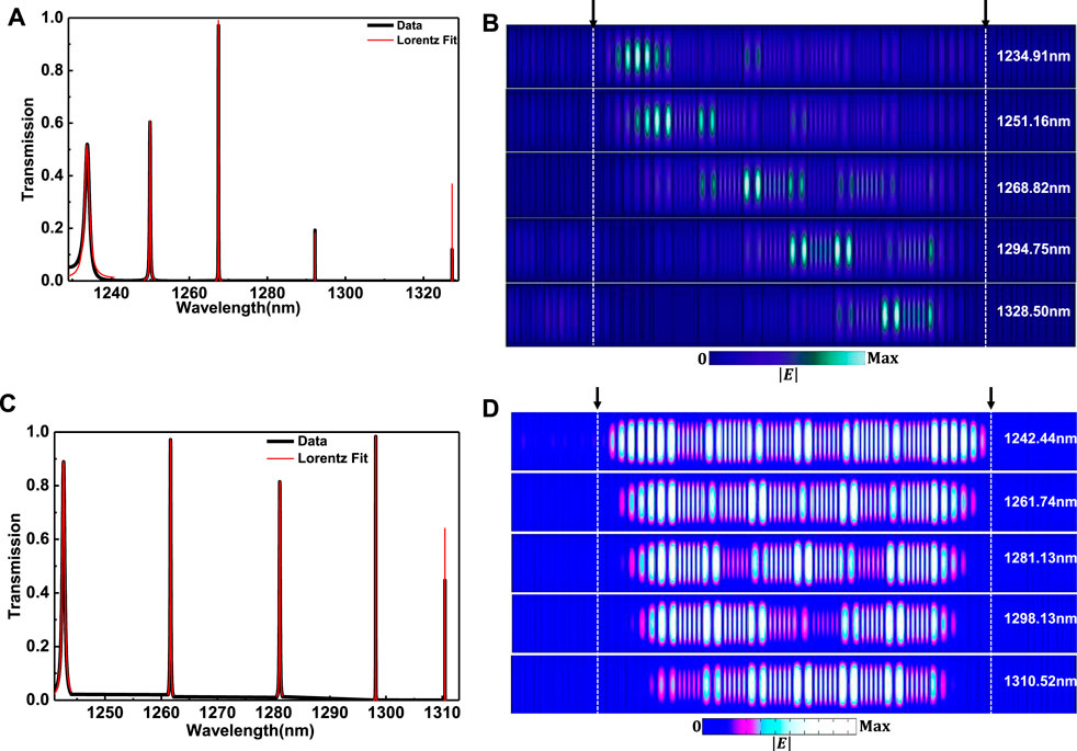
FIGURE 2
www.frontiersin.org

FIGURE 2. (A) The transmission spectrum of the unidirectional rainbow trapping structure with the Lorentzian-fitting curves when dSiO2 is varying from 740 to 765 nm and dSi from 1,000 to 1,100 nm; (B) the electric field |E| intensity distribution of the unidirectional rainbow trapping at wavelengths  1234.91,  1251.16,  1268.82,  1294.75,  and 1328.50  by nm(C) the transmission spectrum of the bidirectional rainbow trapping structure with the Lorentzian-fitting curves of dSiO2 varying from 740 to 765 nm and dSi is fixed at 1,060 nm; (D) the |E| intensity distribution of the bidirectional rainbow trapping at wavelengths 1242.44,  1261.74,  1281.13,  1298.13, and 1310.52 by nm.

To show the formed unidirectional rainbow trapping, the electric field |E| intensity distribution is calculated as shown in Figure 2B. Consequently, multi-modes are excited at the desired wavelengths due to coupling light and the chirped structure. The |E| intensity distributions point out the propagation of light inside the chirped PC. The |E|  intensity rises at the localization points. With gradually increasing the thicknesses of the chirped PC in the propagation direction and light propagates from left to right. In principle, the light will gradually slow down and eventually approach the “stop”. The light of different wavelengths localizes at different spatial positions leading to rainbow trapping in the slow light zone near the left bandgap edge. The property of the bandgap rises when the wavelength of the incident light is in the order of the structure periodicity [15]. The left/right side of the chirped PC is composed of smaller (740nm(dSiO2)+1000nm(dSi) /larger (765nm(dSiO2)+1100nm(dSi) periodicity. This, in turn, affects the shorter/longer wavelengths to be trapped in the appropriate positions. As with increasing the wavelength, the trapped light moves to the right side. The lowest wavelength of 1,234.91 nm is localized near the left TES at the smaller periodicity. With increasing the wavelength, the |E| intensity distributions move to the right till the right TES at the wavelength of 1,328.50 nm. The rainbow trapping bandwidth changed from 1,234.91 to 1,328.50 nm. We find that the formed rainbow is trapped between the two TESs, which act as a strong cavity and enhance the field localization and Q-factor.

The work can extend to construct bidirectional rainbow trapping by progressively increasing one of its thicknesses and solidifying the other. dSiO2 is varying from 740 to 765 nm with an increment of 5 nm and dSi can be fixed at any value from 1,000 to 1,100 nm. The results of fixing dSi at 1060 nm is only shown. Figure 2C shows the transmission spectrum of the bidirectional rainbow trapping structure with the Lorentzian-fitting curves. The resonated transmission peaks that appear at wavelengths by nm are 1242.44,  1261.74,  1281.13,  1298.13, and 1310.52 with FWHM by nm is 0.50719,  0.13104,  0.12927,  0.01949, and 0.00327, respectively. The Q-factor at each resonated transmission peak is 2.45×10³,  9.77×10³,  9.76×10³,  6.66×10⁴,  and 4.00×10⁵, respectively. The |E| intensity distribution is shown in Figure 2D. The field localization is observed in both directions near the two TESs with a smaller wavelength. The two TESs work as a cavity to trap the light inside the chirped PC and make the possibility of light escaping slightly. With increasing the wavelength value, filed localization is shrinking into the chirped PC to form a unidirectional rainbow in both directions simultaneously. Accordingly, the different wavelengths from the wave packet can be segregated spatially at different positions in both directions, and bidirectional rainbow trapping is realized clearly. To the best of our knowledge, this kind of rainbow has not been observed yet in topological photonics. It may possess numerous applications, such as bidirectional devices. Realizing bidirectional rainbow trapping will diminish the footprint of nanophotonic devices in the future.

With increasing the number of alternative layers of the chirped PC, a higher Q-factor and multi-localized modes are obtained. Unidirectional and bidirectional rainbow trapping can be realized by considering ten periods of the chirped PC sandwiched between the two topological PCs. Through the same manner, unidirectional rainbow trapping is detected by gradually increasing dSiO2 and dSi of the chirped PC. dSiO2 is varying from 740 to 785 nm with an increment of 5 nm and dSi from 1,000 to 1,180 nm with an increment of 20 nm. Multi-modes are increased and excited at the desired wavelengths due to coupling light and the increased chirped PC. Figure 3A shows only three localized modes of the |E| intensity distribution of the formed unidirectional rainbow at 1233.58,  1305.83,  and 1410.54  by nm. Different wavelengths localize in different spatial locations. Whereas the wavelength increases, the locations where the light is trapped move to the right side, as shown in Figure 3A. For the bidirectional rainbow trapping, it can be created by gradually thickening dSiO2 and anchoring dSi. A bidirectional rainbow is observed for fixing dSi at any value from 1,000 to 1,180 nm with dSiO2 is varying from 740 nm to 785 nm. Figure 3B shows the results of fixing dSi at 1060 nm of the |E| intensity distribution of the bidirectional rainbow trapping at 1239.93,  1277.23, and 1308.64 by nm. It seen clearly from Figure 3B, as the wavelength value increases, the localization deposited in the chirped PC shrinks to form a unidirectional rainbow in both directions simultaneously. Hence, the bidirectional rainbow can be achieved. Summing up, as the number of periods increases, the transmittance remains high due to both TESs serving as a light-trapping cavity within the chirped PC, but with a very fine meshing and a small step size. It should be noted that increasing the number of periods will increase the manufacturing effort and cost. The less of the periods, the smaller size of the structures, and it is better for the integration of nanophotonic devices. We use six smaller periods for both topological PCs and chirped PC; thus, the trapped PC is 18 periods under the premise of good performance.
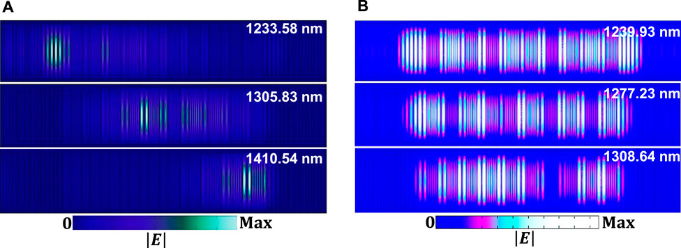
FIGURE 3
www.frontiersin.org

FIGURE 3. (A) The |E| intensity distribution of the unidirectional rainbow trapping at wavelengths  1233.58,  1305.83,  and 1410.54  by nm when dSiO2 is varying from 740 nm to 785 nm with an increment of 5 nm and dSi from 1000 nm to 1180 nm with an increment of 20 nm; (B) the |E| intensity distribution of the bidirectional rainbow trapping at wavelengths 1239.93,  1277.23, and 1308.64 by nm, when dSiO2 is varying from 740 nm to 785 nm with an increment of 5 nm and dSi is fixed at 1060 nm.

FDTD Validation

The proposed PC heterostructure was modeled by the finite-difference-time-domain (FDTD) method to validate the propagation properties. A high resolution (grid size for each dimension) of 30/a1 is used, which is small enough to resolve a minor feature in the fields and structure during the simulation. A PML boundary is added to the edge of the domain of about a1 to absorb all incident energy without producing reflections. A Gaussian source was launched for FDTD calculation and placed in the middle of the trapped PC, as shown in Figure 4A. During the simulation, two monitors are introduced to study the spectral characteristics of the structure at specific wavelength/frequency values and used to measure the steady-state properties for the field distribution. The first and second monitors (M1 and M2) are placed at the trapped PC’s beginning and ending, respectively. Figures 4B,C show the electric field intensity amplitude (Ez2) along the propagation (z) of unidirectional and bidirectional rainbow trapping, respectively, at the center point of the x-y-plane.
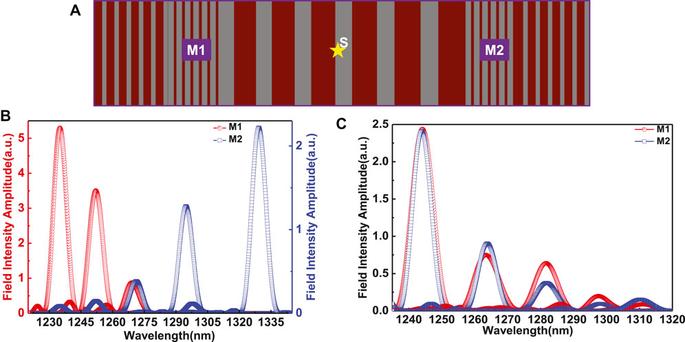
FIGURE 4
www.frontiersin.org

FIGURE 4. (A) FDTD set up of grid size 30/a1 with placing a Gaussian source in the middle of the trapped PC and two monitors (M1, M2) to the left and right, respectively; The electric field intensity amplitude (Ez2)  of (B) unidirectional (C) bidirectional rainbow trapping.

In the case of unidirectional rainbow trapping of dSiO2 linearly varies from 740 to 765 nm with dSi from 1,000 to 1,100 nm, and based on the above explanation, at low wavelengths, M1 records the highest amplitude of the electric field intensity indicating the field localization, and the amplitude is minimized at M2 simultaneously. When the wavelength increases, the intensity begins to decrease at M1 gradually and vice versa at M2 because the field localization moves progressively from left to right with increasing the wavelength, which is illustrated in Figure 4B. A complete agreement with the previous section’s results as shown in Figure 2B. However, there is a minor disparity in the values of wavelengths between FEM and FDTD methods, principally originating from the limited discretization of grid size in FDTD and the number of mesh points for FEM calculations.

Then, to verify bidirectional rainbow trapping, the same above condition are fixed but with dSiO2 is varying from 740 to 765 nm and dSi is fixed at 1,060 nm. The highest field intensity of M1 is located sequentially in the trapped PC from the left side (with the smallest wavelength) to the right side (with the largest wavelength). On the contrary, for M2, the highest field intensity is located sequentially in the trapped PC from the right side (with the smallest wavelength) to the left side (with the largest wavelength), as shown in Figure 4C, confirming the results in Figure 2D. The two TESs works as a cavity which cases exchange with transfer the energy flow between the two cavities of the forward and backward propagation. Meanwhile, rainbow trapping is observed in both FEM and FDTD methods, which confirms our simulation results.

Immune to Defects

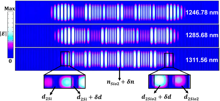
The critical step is to confirm that the formed rainbow is robust and topologically protected from disorders by the two TESs on both sides. Some disorders are introduced in the trapped PC (PC2, chirped PC and PC2 ) between the two TESs through changing thickness or refractive index of some layers. Three cases are considered; the last layer of PC2 (d2Si) from the TPCL is deformed by δd=±0.05a2. Via the same amount of deformation (±0.05a2) is applied on the first layer of PC2 (d2Si) from the TPCR. The last case is changing the refractive index of the middle SiO2 in the chirped PC by δn=±0.01. By applying each case individually or combined, rainbow tapping is achieved with a slight shifting in the wavelength. Figure 5 shows the realization of bidirectional rainbow trapping with disordering of all deformed cases together. We can see clearly, the |E| intensity distribution is highly localized in the trapped PC due to topological protection by the two TESs even in the presence of disorders. Bidirectional rainbow trapping is still observed on both sides but with slight shifting in wavelengths. Accordingly, the formed rainbow is robust and immune to disorders.

FIGURE 5
www.frontiersin.org

FIGURE 5. Bidirectional rainbow trapping realization with disordering of some parameters, the inset shows the deformation in last and first layers of PC2 from TPCL and TPCR respectively.

Trivial Rainbow Trapping

Trivial rainbow trapping is realized through the same modality by introducing a chirped PC as a trapped structure between two conventional PCs. In the exact mechanism as mentioned above, introducing a chirped PC as a sandwiched between two topological PCs (TPCL and TPCR). Under the same conditions and variables, values of PC1 and PC2  are setups, and the chirped PC consists of 18 periods from SiO2 and Si as shown in Figure 6A. The bidirectional trivial rainbow trapping as in the content of the topological case cannot be formed when  dSi is fixed at any value from 1,000 to 1,340 nm and dSiO2 is varying from 740 to 825 nm. This is because the two TESs act as a cavity to transfer the energy flow between the two cavities of the forward and backward propagation and make the possibility of light escaping slightly. Therefore, the formed bidirectional rainbow may occur in the topological case.

FIGURE 6
www.frontiersin.org

FIGURE 6. (A) Schematic diagram of the chirped PC sandwiched between two PCs. The |E| intensity distribution of the trivial unidirectional rainbow trapping of 18 periods of the trapped chirped PC between PC1 and PC2 (B) without defects; (C) with defects by the disordering of some parameters (deformation in last and first layers of PC1 and PC2 respectively).

Unidirectional trivial rainbow trapping can be formed with the same conditions for topological cases. When dSiO2 is varying from 740 to 825 nm with an increment of 5 nm and dSi from 1,000 to 1,340 nm with an increment of 20 nm, as shown in Figure 6B. The trivial unidirectional rainbow trapping is observed but lacks highly field localization and light confinement compared with the topological case due to the robust field localization between the two TES, which resulted in a robust optical localization in the chirped region. Some disorders are introduced. The last and the first layer of PC1 and PC2 (d2SiO2) on the left and right sides respectively are deformed by δd=±0.05a2 with changing the refractive index of the middle SiO2 in the chirped PC by δn=±0.01. Figure 6C shows the formed trivial rainbow trapping with disordering. Two points are observed clearly between the two cases; some localized modes occurred at the same wavelengths, and others slightly shifted. However, the case of 1,493.69 nm is localized at a different position without defects.

Conclusions

In conclusion, a unidirectional and bidirectional rainbow trapping have been investigated. The main idea is based on trapping a chirped PC as a sandwich between two edge states. At the same time, the two edge states work as a cavity to trap the light inside the chirped structure and can be propagated in both directions. Consequently, different frequencies from the wave packet segregate at different positions in both directions. Moreover, the propagation properties are validated using FDTD by measuring the electric field intensity amplitude. In addition, we confirmed that the formed rainbow is robust and topologically protected even in the presence of disorders. Bidirectional rainbow trapping will open a feasible way for numerous applications, e.g., multichannel wavelength demultiplexers, bidirectional optical filter, and bidirectional laser.

Data Availability Statement

The original contributions presented in the study are included in the article/Supplementary Material, further inquiries can be directed to the corresponding author.

Author Contributions

SE conceived the idea, performed the numerical simulations, and wrote the draft of the manuscript. CL checked the simulation results and revised the manuscript. CL supervised the project.

Funding

National Natural Science Foundation of China (91850117, 11654003); Beijing Institute of Technology Research Fund Program for Young Scholars.

Conflict of Interest

The authors declare that the research was conducted in the absence of any commercial or financial relationships that could be construed as a potential conflict of interest.

Publisher’s Note

All claims expressed in this article are solely those of the authors and do not necessarily represent those of their affiliated organizations, or those of the publisher, the editors and the reviewers. Any product that may be evaluated in this article, orclaim that may be made by its manufacturer, is not guaranteed or endorsed by the publisher.

References

1. Tsakmakidis KL, Boardman AD, Hess O. 'Trapped Rainbow' Storage of Light in Metamaterials. Nature (2007) 450(7168):397–401. doi:10.1038/nature06285

PubMed Abstract | CrossRef Full Text | Google Scholar

2. Hu H, Ji D, Zeng X, Liu K, Gan Q. Rainbow Trapping in Hyperbolic Metamaterial Waveguide. Sci Rep (2013) 3(1):1249. doi:10.1038/srep01249

PubMed Abstract | CrossRef Full Text | Google Scholar

3. Xu Z, Shi J, Davis RJ, Yin X, Sievenpiper DF. Rainbow Trapping with Long Oscillation Lifetimes in Gradient Magnetoinductive Metasurfaces. Phys Rev Appl (2019) 12(2):024043. doi:10.1103/PhysRevApplied.12.024043

CrossRef Full Text | Google Scholar

4. Gan Q, Ding YJ, Bartoli FJ. "Rainbow" Trapping and Releasing at Telecommunication Wavelengths. Phys Rev Lett (2009) 102(5):056801. doi:10.1103/PhysRevLett.102.056801

PubMed Abstract | CrossRef Full Text | Google Scholar

5. Chen L, Wang GP, Gan Q, Bartoli FJ. Rainbow Trapping and Releasing by Chirped Plasmonic Waveguides at Visible Frequencies. Appl Phys Lett (2010) 97(15):153115. doi:10.1063/1.3502487

CrossRef Full Text | Google Scholar

6. Schuller JA, Barnard ES, Cai W, Jun YC, White JS, Brongersma ML. Plasmonics for Extreme Light Concentration and Manipulation. Nat Mater (2010) 9(3):193–204. doi:10.1038/nmat2630

PubMed Abstract | CrossRef Full Text | Google Scholar

7. Chaplain GJ, De Ponti JM, Aguzzi G, Colombi A, Craster RV. Topological Rainbow Trapping for Elastic Energy Harvesting in Graded Su-Schrieffer-Heeger Systems. Phys Rev Appl (2020) 14(5):054035. doi:10.1103/PhysRevApplied.14.054035

CrossRef Full Text | Google Scholar

8. Ungureanu B, Makwana MP, Craster RV, Guenneau S. Localizing Elastic Edge Waves via the Topological Rainbow Effect. Phys Rev Appl (2021) 15(1):014057. doi:10.1103/PhysRevApplied.15.014057

CrossRef Full Text | Google Scholar

9. Shen Y, Fu J, Yu G. Rainbow Trapping in One-Dimensional Chirped Photonic Crystals Composed of Alternating Dielectric Slabs. Phys Lett A (2011) 375(43):3801–3. doi:10.1016/j.physleta.2011.08.023

CrossRef Full Text | Google Scholar

10. Lu C, Wang C, Xiao M, Zhang ZQ, Chan CT. Topological Rainbow Concentrator Based on Synthetic Dimension. Phys Rev Lett (2021) 126(11):113902. doi:10.1103/PhysRevLett.126.113902

PubMed Abstract | CrossRef Full Text | Google Scholar

11. Zhang H, Qian L, Wang C, Lu C., Liu Y, Chen J, et al. Topological Rainbow Based on Graded Topological Photonic Crystals. Opt Lett (2021) 46(6):1237–40. doi:10.1364/OL.419271

PubMed Abstract | CrossRef Full Text | Google Scholar

12. Hayran Z, Kurt H, Staliunas K. Rainbow Trapping in a Chirped Three-Dimensional Photonic crystal. Sci Rep (2017) 7(1):3046. doi:10.1038/s41598-017-03454-w

PubMed Abstract | CrossRef Full Text | Google Scholar

13. Elshahat S, Abood I, Esmail MSM, Ouyang Z, Lu C. One-Dimensional Topological Photonic Crystal Mirror Heterostructure for Sensing. Nanomaterials (2021) 11(8):1940. doi:10.3390/nano11081940

PubMed Abstract | CrossRef Full Text | Google Scholar

14. Dal Lago V, Atala M, Foa Torres LEF. Floquet Topological Transitions in a Driven One-Dimensional Topological Insulator. Phys Rev A (2015) 92(2):023624. doi:10.1103/PhysRevA.92.023624

CrossRef Full Text | Google Scholar

15. Kurt H, Yilmaz D. Rainbow Trapping Using Chirped All-Dielectric Periodic Structures. Appl Phys B (2013) 110(3):411–7. doi:10.1007/s00340-012-5270-8

CrossRef Full Text | Google Scholar

Keywords: rainbow trapping, topological photonic crystal, nanophotonic devices, chirped photonic crystal, topological edge state

Citation: Elshahat S and Lu C (2022) Bidirectional Rainbow Trapping in 1-D Chirped Topological Photonic Crystal. Front. Phys. 10:831203. doi: 10.3389/fphy.2022.831203

Received: 08 December 2021; Accepted: 10 January 2022;
Published: 03 February 2022.

Edited by:

Yiqi Zhang, Xi’an Jiaotong University, China

Reviewed by:

Xiao-Dong Chen, Sun Yat-sen University, China
Chen Shen, Rowan University, United States
Fangwei Ye, Shanghai Jiao Tong University, China

Copyright © 2022 Elshahat and Lu. This is an open-access article distributed under the terms of the Creative Commons Attribution License (CC BY). The use, distribution or reproduction in other forums is permitted, provided the original author(s) and the copyright owner(s) are credited and that the original publication in this journal is cited, in accordance with accepted academic practice. No use, distribution or reproduction is permitted which does not comply with these terms.

*Correspondence: Cuicui Lu, Y3VpY3VpbHVAYml0LmVkdS5jbg==

Disclaimer: All claims expressed in this article are solely those of the authors and do not necessarily represent those of their affiliated organizations, or those of the publisher, the editors and the reviewers. Any product that may be evaluated in this article or claim that may be made by its manufacturer is not guaranteed or endorsed by the publisher.