- 1Institute of High Energy Physics, CAS, Beijing, China
- 2School of Nuclear Science and Technology, University of Chinese Academy of Sciences, Beijing, China
Following the discovery of the Higgs boson at the LHC in 2012, new large colliders are being considered and studied by the international high-energy community to explore the Higgs boson in details and to probe new physics beyond the Standard Model. In China, a two-stage circular collider project, CEPC-SPPC was proposed and is under study. The first stage, CEPC (Circular Electron Positron Collier, a so-called Higgs factory) is focused on the Higgs physics, and the second stage, SPPC (Super Proton-Proton Collider) will be an energy frontier collider and a discovery machine beyond the LHC. The two colliders will share a same tunnel of 100 km in circumference, with a goal of 250 GeV in center-of-mass for CEPC and 75 TeV for SPPC Phase-I and 125–150 TeV for the SPPC ultimate goal. This article presents the design concept of the SPPC and some study results about the key accelerator physics problems and technical issues, which include luminosity optimization, beam collimation, beam-beam effects, longitudinal beam dynamics, high-field magnets and beam screen.
1 Science Reach at the SPPC
SPPC (Super Proton-Proton Collider) is envisioned to be an extremely powerful machine, far beyond the scope of the Large Hadron Collider (abbr. as LHC), with a center-of-mass energy of 75 TeV, a nominal luminosity of 1.0 × 1035 cm−2s−1 per interactive point (abbr. as IP) at the collision start, and an integrated luminosity of 30 ab−1 assuming 2 interaction points and 10–15 years of operation. A later upgrade to even higher luminosities is also possible. While the luminosity has a more modest effect on energy reach, in comparison with higher beam energy [1], raising the luminosity will likely be much cheaper than increasing the energy. The ultimate upgrading phase for SPPC is to explore physics at the center-of-mass energy of 125–150 TeV.
The CEPC (Circular Electron-Positron Collider, or a Higgs Factory) and the SPPC together will have the capability to precisely probe Higgs physics [2]. However, what the community expects more eagerly is that SPPC will explore directly a much larger region of the landscape of new physics models, and make a huge leap in our understanding of the physical world. There are many issues in energy-frontier physics that SPPC will explore, including the mechanism of Electroweak Symmetry Breaking (EWSB) and the nature of the electroweak phase transition, the naturalness problem, and the understanding of dark matter. While these three questions can be correlated, they also point to different exploration directions leading to more fundamental physics principles. SPPC will explore new ground and have great potential for making profound breakthroughs in answering all of these questions.
Extending the CEPC Higgs factory program, billions of Higgs bosons will be produced at the SPPC. This huge yield will provide important physics opportunities, especially for the rare but relatively clean physics processes.
As an energy frontier machine, the SPPC could discover an entirely new set of particles in the O (10 TeV) regime, and unveil new fundamental physics principles. One of the most exciting opportunities is to address the naturalness problem. This problem stems from the vast difference between two energy scales: the currently probed electroweak scale and a new fundamental scale, such as the Planck scale. Solutions to the naturalness problem almost inevitably predict the existence of a plethora of new fundamental particles not far from the electroweak scale. Such new particles will shed light on the underlying physics principles that link the low energy scale of the electroweak processes, including the light Higgs boson mass, with respect to the extremely high value of the Planck scale that sets the upper energy limit of applicability of quantum physics as we know it. Searching for these possible new particles at the LHC can probe the level of fine-tuning down to 10–2, while SPPC would push this down to the unprecedented level of 10–4, beyond the common concept of the naturalness principle.
Dark matter remains one of the most puzzling issues in particle physics and cosmology. Weakly interacting massive particles (WIMPs) are still the most plausible dark matter candidates. If dark matter interacts with Standard Model (SM) particles with coupling strength similar to that of the weak interaction, the mass of a WIMP particle could easily be in the TeV range, and likely to be covered at SPPC energy. Combining the relevant bounds on the mass and coupling from the direct (underground) and the indirect (astroparticle) dark matter searches, SPPC would allow us to substantially extend the coverage of the WIMP parameter space for large classes of models.
At the SPPC energy regime, all the SM particles are essentially “massless”, and electroweak symmetry and flavor symmetry will be restored. The top quark and electroweak gauge bosons should behave like partons in the initial state, and like narrow jets in the final state. Understanding SM processes in such an unprecedented environment poses new challenges and offers unique opportunities for sharpening our tools in the search for new physics at higher energy scales.
2 The SPPC Complex
2.1 General
Since the CEPC-SPPC project is planned to be developed in two major phases: Phase One with the construction of CEPC has a timeline of 2026–2034; Phase Two with the construction of SPPC has a timeline of 2042–2050. Longer construction period for SPPC might be needed for building up the complex injector chain before the collider rings.
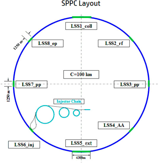
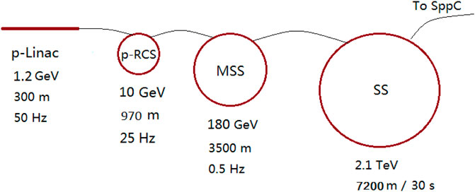
SPPC is a complex accelerator facility and will be able to support research in different fields of physics, similar to the multi-use accelerator complex at CERN. Besides the energy frontier physics program in the collider, the beams from each of the four accelerators in the injector chain can also support their own physics programs. The four stages, shown in Figure 1 and with more details in Figure 10, are a proton linac (p-Linac), a rapid cycling synchrotron (p-RCS), a medium-stage synchrotron (MSS) and the final stage synchrotron (SS). This research can occur during periods when beam is not required by the next-stage accelerator. For example, the high-power proton beam of about 0.8 MW from the p-Linac can be used for production of intense beams of neutrons, muons and rare isotopes for a wide range of research. The high-power beams of 10 GeV from the p-RCS and 180 GeV from the MSS can be used to produce very powerful neutrino beams for neutrino oscillation experiments and the high energy beam from the SS can be used for hadron physics research.
In summary, SPPC will play a central role in experimental particle physics in the post-Higgs-boson discovery era. It is the natural next stage of the circular collider physics program after CEPC. Combining these two world-class machines will be a significant milestone in our pursuit of the fundamental laws of nature.
2.2 Design Goals
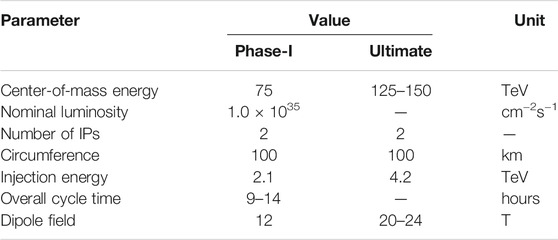
SPPC is a proton-proton collider, a discovery machine at the energy frontier. Given the 100 km circumference tunnel which is jointly defined by CEPC and SPPC, we will try to achieve the modest center-of-mass energy in proton-proton collisions with the anticipated accelerator technology and modest cost in late 2030s, but a more ambitious goal to go to higher energy is also preserved. This, of course, depends on the magnetic field that bends the protons around the collider rings: 12 T using magnets with iron-based high-temperature superconductors (iron-based HTS) for SPPC Phase-I and 20–24 T also using iron-based HTS magnets for Phase-II. Taking into account the expected evolution in detector technology, we can expect that the nominal luminosity of 1.0 × 1035 cm−2s−1 will be usable at the early phase but high-luminosity upgrade is also considered. At least two IPs will be made available.
This article describes the SPPC layout, basic design parameters, and its major challenges in accelerator physics and technology. It also explores the compatibility in the same tunnel with the previously built CEPC and different operating modes such as electron-proton, proton-ion, and electron-ion. Some key parameters are shown in Table 1.
2.3 Overview of the SPPC Design
The collider will share the same tunnel with the previously built CEPC, of circumference 100 km. A bypass scheme to avoid confliction is possible to keep the CEPC operating when adding the SPPC. The shape and symmetry of the tunnel is a compromise between the two colliders. The SPPC requires relatively longer straight sections which will be described later. This means eight identical arcs and eight long straight sections for two large detectors, injection and extraction, RF stations and a complicated collimator system. Based on expected progress in HTS technology, especially the iron-based HTS technology and also high-field magnet technology in the next 15–20 years, we expect that a field of 12 T will be attainable for the main dipole magnets with very reasonable cost or much cheaper than that based on Nb3Sn superconductors. Twin-aperture magnets will be used for the two-ring collider. A filling factor of 78% in the arcs (similar to LHC) is assumed. The SPPC will provide beams at a center-of-mass energy of about 75 TeV.
With a circulating beam current of about 0.73 A and small beta functions (β*) of 0.75 m at the collision points, the nominal or initial luminosity can reach 1.0 × 1035 cm−2s−1 per IP. The high beam energy, high beam current and high magnetic field will produce very strong synchrotron radiation which will impose critical requirements on the vacuum system that is based on cryogenic pumping. We expect that this technical challenge will be solved in the next 2 decades by developing efficient beam screens to extract the heavy heat load from the synchrotron radiation and reduce the electron cloud density within the beam apertures. If forced to lower the synchrotron radiation power, we would have to reduce the bunch population or the number of bunches and try to achieve a smaller β* in order to maintain high luminosity.
As in other proton colliders using superconducting magnets, the injection energy is mainly defined by the field quality of the magnets at the bottom of their range. Persistent currents in the coils (magnetization) distort the field distribution at injection energy. Other factors favoring relatively higher injection energy are the coupling impedance, which is important to collective beam instabilities, the smaller emittance required to reduce apertures of beam screen and magnet, and the requirement on the good-field-region of the magnets. At SPPC, we have adopted a compromised injection energy of 2.1 TeV. The injector chain pre-accelerates the beam to injection energy with the required bunch current, bunch structure, and emittance. The injection chain determines the beam fill period. To reach 2.1 TeV, a four-stage injector chain is proposed: the p-Linac to 1.2 GeV, the p-RCS to 10 GeV, the MSS to 180 GeV and the SS to 2.1 TeV.
If not controlled, synchrotron cooling in SPPC would rapidly reduce the beam emittances and cause excessive beam-beam tune shifts. Noise in transverse deflecting cavities must be used to limit the minimum transverse emittances (emittance heating), and thus tune shifts. Without luminosity leveling, and with constant beam-beam tune shift, the luminosity decays exponentially from its initial peak with a lifetime of approximately 14.2 h. A shorter turnaround time (defined as the period in a machine cycle excluding the collision period), 0.8 h as base-case and 2.4 h as average-case is preferable to maximize the integrated luminosity.
There are many technical challenges in designing and building such a collider, including its injector chain. The two most difficult ones are the development and production of 12-T magnets with iron-based HTS, and the beam screen associated with very strong synchrotron radiation. Significant R&D efforts in the coming decade are needed to solve these problems.
3 Key Accelerator Physics Issues
3.1 Main Design Parameters
3.1.1 Collision Energy and Layout
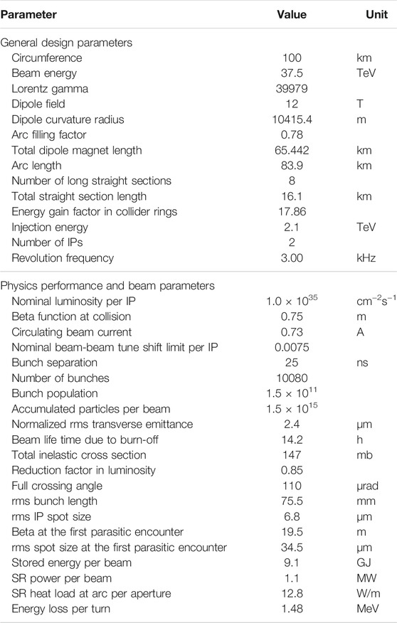
To reach the design goal for the 75-TeV center-of-mass energy with a circumference of 100 km, a modest magnetic field of 12 T is required, which is not far from the state-of-the-art magnet technology using Nb3Sn superconductors. However, iron-based HTS technology has a bright expectation to be available and much cheaper in 10–15 years, and to generate a field higher than 20 T in the far future. Thus iron-based HTS magnet technology is chosen for SPPC. Even with the long circumference, the arc sections should be designed to be as compact as possible to provide necessary long straight sections. Although different lattice schemes are under study, it is assumed that a traditional FODO focusing structure (using uniformly distributed focusing and defocusing elements) is everywhere, except at the IPs where triplets are used to produce the very small β*. The arcs represent most of the circumference, and the arc filling factor is taken as 0.78, similar to the LHC [3]. A key issue here is to define the number of long straight sections and their lengths. They are needed to produce those very small beta functions where the large physics detectors are to be placed, and for hosting the beam injection and extraction (abort) systems, as well as collimation systems and RF stations. Some compromises have to be made to have a relatively compact design of the long straight sections, and should be compatible with the CEPC layout. A total length of about 16.1 km is reserved for the long straight sections, with eight long straight sections of which two are 4.3 km long and the six others are 1.25 km long. With this configuration, the top beam energy is 37.5 TeV corresponding to 75 TeV in center-of-mass energy. The main parameters are listed in Table 2.
3.1.2 Luminosity
The initial luminosity (or nominal luminosity) of 1.0 ×1 035 cm−2s−1 is much higher than in previously built machines such as the Tevatron [4] and LHC [3] and in designs such as SSC [5], VLHC [6], HE-LHC [7], and comparable to FCC-hh (Future Circular Collider–the Hadron Collider) [8, 9], though perhaps lower than in the HL-LHC [10]. In order to achieve this high luminosity, a large number of bunches and high bunch population are needed. These will be supplied by a powerful injector chain. Instant luminosity can be expressed by
where L, Nb, nb, f,
Another important parameter is the average, and thus integrated luminosity. One must consider the loss of stored protons from collisions, the cycle turnaround time, and the shrinking of the transverse emittance due to synchrotron radiation. The luminosity optimization and the so-called leveling are addressed in Section 3.2.3.
3.1.3 Bunch Structure and Population
Many bunches with relatively small bunch spacing are desirable for achieving high luminosity operation. However, the bunch spacing can be limited both by parasitic collisions in the proximity of the IPs, and by the electron cloud instability. One also needs to consider the ability of the detector trigger systems to cope with short bunch spacing. Although the bunch gap of 25 ns was designed as a baseline for LHC, the machine was operated with 50 ns bunch spacing in Run 1. This was due to problems in operation mainly from the electron cloud effect. The problems related to 25 ns at LHC was overcome in Run 2. Therefore, we have also adopted 25 ns for the nominal bunch spacing at SPPC. The bunch spacing of 25 ns is defined by the RF system in the p-RCS of the injector chain and preserved from there onward in the following steps of the injection chain [12]. The possibility of shorter bunch spacing will be investigated and is discussed below in Section 3.2.3.
Time gaps between bunch trains are needed for beam injection and extraction in both collider rings and the injector chain. Their lengths depend on the practical designs of the injection and extraction (abort) systems, and the rise time of the kickers for beam extraction from SPPC, assumed now to be a few microseconds. The bunch filling is taken to be about 76% of the ring circumference, which is smaller than in the LHC, and is due to the more injection gaps or batch gaps that are needed here. These gaps in the bunch structure have a significant impact on the beam dynamics during collision. On the one hand, the gaps between bunch trains are useful in suppressing collective beam instabilities; on the other hand, some bunches will meet empty bunches at the collision points or the first parasitic collision points, and those irregular bunches are called PACMAN bunches [13].
3.1.4 Beam Sizes at the IPs
The beam sizes at the IPs are determined by the β* of the insertion lattice and the beam emittance. The initial normalized emittance of 2.4 μm is predefined in the p-RCS of the injector chain and preserved with a slight increase in the course of reaching the top energy of the SPPC due to many different factors such as nonlinear resonance crossings. The nominal beam size is 6.8 μm in rms corresponding to 0.75 m for β* and 2.4 μm for the transverse emittance. However, at the top energy of 37.5 TeV and in the later part of the acceleration stage, synchrotron radiation will take effect, with damping times about 2.35 and 1.17 h for the transverse and longitudinal emittances, respectively. This will allow emittances to reduce significantly after the collision start time with respect to their initial values at the moment when the beams reach the top energy. Although smaller beam sizes at the IPs are favorable for luminosity, the emittances cannot be allowed to fall freely without limit because of beam-beam tune shift and detector data pileup that is caused by too high number of events per bunch crossing to be handled by the detector. Thus a stochastic emittance heating system is required to limit the synchrotron radiation cooling and control the emittance level during the collision process.
3.1.5 Crossing Angle at the IPs
To avoid parasitic collisions near the IPs producing background for experiments, it is important to separate the two beams, except at the IPs, using a crossing angle between the two beams. The crossing angle is chosen to avoid the beams overlapping at the first parasitic encounters at 3.75 m from the IPs when the bunch spacing is 25 ns At these locations the separation is no less than 12 times the rms beam size. At the SPPC, this crossing angle at the collision energy is about 110 μrad. Compared with head-on collisions, this bunch crossing angle will result in a luminosity reduction of about 15%. The crossing angle could be increased later in a more realistic design, and would have to be increased if smaller bunch spacing were to be adopted, as discussed in Section 3.2.3. The crossing angle has also an important impact to the dynamic aperture caused by the beam-beam effects, which is discussed in Section 3.3.
With a small bunch spacing the crossing angle must be larger, and the reduction of luminosity would be larger. However, there will be no luminosity loss with crossing angles when crab cavities are used. The crossing angle may be different at injection due to different lattice settings and larger emittance.
At the superconducting quadrupole triplets, the two beams are separated from each other by the crossing angle, and the apertures of the quadrupoles are increased significantly.
3.1.6 Turnaround Time
Turnaround time is about the total time period in a machine cycle when the beams are out of collision, including the programmed countdown checking time before injection, the final check with a pilot shot, the beam filling time with SS beam pulses, the ramping up (or acceleration) time, and the ramping down time. Filling one SPPC ring requires 10 SS beam pulses, which means a minimum filling time of about 14 min including pilot pulses. The ramping up and down times are each about 12.4 min. Altogether, the minimum turnaround time is 48 min, or about 0.8 h. However, the experience at LHC and other proton colliders [14] shows that only about one third of the operations from injection to the top energy are successful, thus the average turnaround time is taken to be 2.4 h. This is considered acceptable, and with a luminosity run time of 4–8 h, during which the beams are in collision, it gives a total cycle time of about 7–11 h.
3.1.7 RF Parameters
The main acceleration system at SPPC uses 400 MHz superconducting cavities. However, an additional RF system of 200 MHz is considered helpful for the longitudinal matching from the SS to the collider during injection, and a dual RF system of 400 and 800 MHz is found beneficial in suppressing instabilities and increasing luminosity at collision [12]. Although the ramping-up time is mainly defined by the superconducting magnets, the RF system must provide sufficient voltage during the process to keep up the acceleration rate with a large longitudinal acceptance. When nearing the final stage of acceleration, synchrotron radiation will play a significant role. About 10 MV in RF voltage is needed to compensate the synchrotron radiation, and the situation is similar during the collisions (and the preparation phase bringing the beams into collision). A total RF voltage of either 24 or 32 MV per beam will be provided by the 400 MHz system. Stochastic noise must be introduced to raise the longitudinal emittance to provide the long bunches required to avoid detector pileup, and avoid instabilities.
3.2 Synchrotron Radiation Related Effects
3.2.1 Synchrotron Radiation at Collision
Synchrotron radiation (SR) power is proportional to the fourth power of the Lorentz factor and the inverse of the radius of curvature in the dipoles, and becomes an important effect at multi-TeV energies using high-field superconducting dipoles. With the beam current of 0.73 A and magnetic field of 12 T, the synchrotron radiation power reaches about 12.8 W/m per aperture in the arc sections, about sixty times of that at LHC. The critical photon energy is about 1.8 keV. There is also a synchrotron radiation effect in the high-gradient superconducting quadrupole magnets.
At the SPPC, synchrotron radiation imposes severe technical challenges to the vacuum system and a probable limit on the circulating current. If absorbed at the liquid helium temperature of the magnet bores, the synchrotron radiation’s heat load would be excessive, so it must be absorbed at a higher temperature. A beam screen, or other photon capture system, must be situated between the beam and the vacuum chamber. This limits the beam tube aperture, raises the beam impedance, and/or increases the required superconducting magnet bore radius. There is also a problem related to the electron cloud formation by synchrotron radiation. The technical challenges of the vacuum system and beam screen are discussed in detail in Section 4.2.
The synchrotron radiation also has an important impact on the beam dynamics. Without intervention, both the longitudinal and transverse emittances will shrink with lifetimes of about 2.35 and 1.17 h, respectively. The short damping times may help eliminate collective beam instabilities. One may exploit this feature to enhance the machine performance by allowing the transverse emittances to fall and to increase the luminosity. Nevertheless, to avoid excessive beam-beam tune shift (see Section 3.3), a stochastic transverse field noise systems will have to be installed to control the emittance reduction.
3.2.2 Luminosity Optimization and Leveling
With the nominal collision parameters, the number of events per bunch crossing (418) is higher than current detectors could accept, but it is assumed to be acceptable with future detector technology. It means that no significant pileup will happen. However, synchrotron cooling of the transverse emittance can generate luminosities greater than its initial value, and further raise the numbers of events per bunch crossing. Optimum physics use would then require a constraint on the events per bunch crossing, requiring a mechanism to limit the maximum luminosities but increase the average luminosities. Such mechanism is called luminosity leveling and could be implemented by controlling either the β* or the emittances using the stochastic heating system. Another option is to vary the crossing angle.
Six different operation scenarios to obtain the average luminosity targets have been considered [15]. Table 3 and Figure 2 show the relevant parameters as a function of time. In all cases, the collision times are chosen to give the maximum average luminosities assuming the baseline turnaround time of 2.4 h. The increased average luminosities with an ideal turnaround time of 0.81 h are shown in parentheses in columns 5 and 6 in Table 3. Crab cavities are used to avoid luminosity reduction due to the hourglass effect, and this becomes critical if the transverse emittance is damped but a larger longitudinal emittance is maintained.
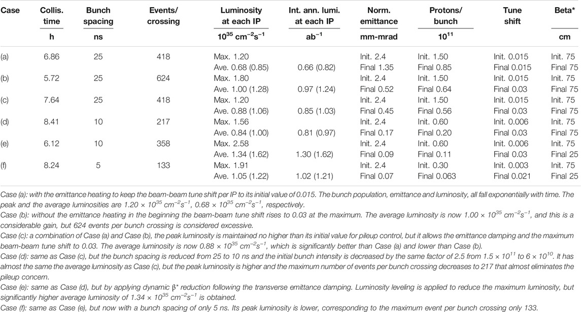
TABLE 3. Relevant parameters during operation are summarized for six cases: (a) a fixed tune shift; (b) allowing the tune shift to rise to 0.03; (c) as in (b) but leveling the luminosity to its initial value; (d) as for (c) but with bunch spacing of 10 ns; (e) as for (d) but reducing β* proportional to the emittance down to 25 cm; (f) as for (e) but with bunch spacing of 5 ns. All values are for run times maximized for a turnaround time of 2.4 h, except for the parenthesized average luminosities and integrated annual luminosities that are for a turnaround time of 0.81 h.
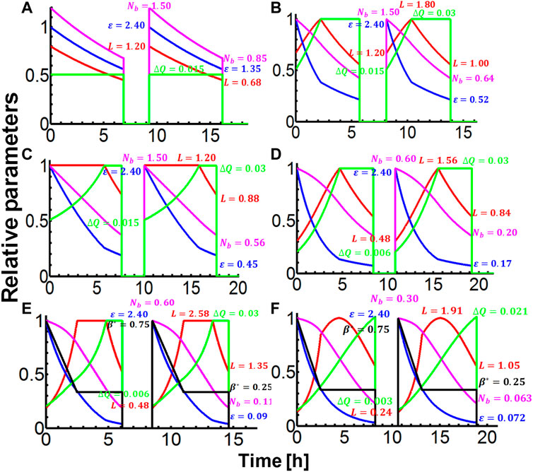
FIGURE 2. Evolution of parameters vs. time with a turnaround time of 2.4 h and bunch spacing of 25 ns. Red: luminosity, magenta: number of protons per bunch, blue: transverse emittance, green: beam-beam tune shift, black: beta* at the IP. (A) with fixed tune shift; (B) allowing the tune shift to rise to 0.03; (C) as in (B) but with the luminosity “leveled” at its initial value; (D) as in (C) but bunch spacing of 10 ns; (E) as for (D) but reducing beta* in proportion to emittance down to 25 cm; (F) as for (E) but with bunch spacing of 5 ns. In plots (A), (B), (C) and (D), beta* is kept constant at the nominal 0.75 m.
The shorter bunch spacings in Cases (d), (e), and (f) can be obtained by applying a bunch splitting scheme in MSS [16].
3.2.3 Dynamic β* Reduction
To avoid beam loss, the beam rms size σ must be kept below a given fraction of the apertures of the inner quadrupole triplets at the IPs. If L* is the distance from the triplet to the IP, then the beam size is given approximately by σ∼L*(ε/β*)1/2, which sets a minimum acceptable β*. As there is no design on the detector and machine-detector interface, L* is currently assumed to 36 m or 50% more than that of the LHC. However, as the emittance ε falls from synchrotron damping, then the β* can be reduced in proportion, without increasing σ at the IPs. A lower limit for β* may be set by lattice considerations, and the spot size at the IPs should not approach too close to the bunch length to avoid serious hour-glass effects. In the examples in Table 3 and Figure 2, β* reduction was limited to 0.25 m or one third of its initial value of 0.75 m.
3.3 Beam-Beam Effects
The beam-beam effects, which could lead to emittance growth, lifetime drop, and instabilities, have a very important effect on the luminosity of a collider. They come from both head-on interactions and long-range or parasitic interactions. There are several different beam-beam effects affecting the performance of a proton-proton collider: the incoherent beam-beam effects which influence beam lifetime and dynamic aperture; the PACMAN effects which will cause bunch to bunch variation; and coherent effects which will lead to beam oscillations and instabilities.
The nominal parameters given in Table 2 are used for the preliminary study of the beam-beam effects. It is reasonable to choose a conservative nominal beam-beam tune shift parameter as 0.0075 or 0.015 for two IPs. However, LHC has reported stable operation with a total beam-beam tune shift ΔQtot∼0.03 with three IPs [17], and the simulations in Ref. [18] predict that the beam-beam limit at LHC might be even larger. Thus, this limit was used for the examples in Figure 2.
In fact, the non-linear effects from parasitic beam-beam interactions that will be addressed below in detail are even more important in dynamic aperture, which determines the bunch spacing and the crossing angle. It is also important to consider their effects at the injection energy where the geometrical beam emittance is larger.
3.3.1 Incoherent Effects
Each particle in a beam will feel a strong nonlinear force when the beam encounters the counter rotating beam, with deleterious effects on the dynamic behavior of the particle. This nonlinear interaction will lead to an amplitude dependent tune spread for the particles in both transverse planes, which should be studied to keep the tunes away from crossing dangerous resonance lines. Earlier experiences at both the Tevatron [4] and LHC [3], required the total tune spread from all IP crossings to be kept to no more than 0.015. However, operations with larger tune shifts such as 0.02–0.03 have been reported at both Tevatron [19, 20] and LHC [21]. At SPPC, the beam-beam tune footprints from theory and simulations for two different initial tunes are shown in Figure 3, which include both head-on and parasitic collisions [22].
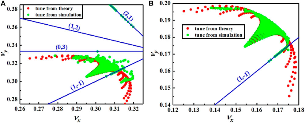
FIGURE 3. Footprint by the beam-beam interactions for different initial nominal tunes: (A) (0.31, 0.32) and (B) (0.17, 0.19). Red and green points are from the theoretical calculation and the simulations, respectively. The lines show all nearby resonances up to the fourth order. The numbers (m, n) in brackets define resonances mνx + nνy = p, where p is an integer.
3.3.2 PACMAN Effects
The circumference and bunch number at the SPPC are 3.7 and 3.5 times of those at the LHC, respectively. With the similar bunch spacing of 25 ns it is expected that the PACMAN effects may have a similar influence as seen at the LHC. Only about half of the total bunches at the SPPC would be regular bunches that will meet the counter bunches at the IPs. The identification of regular bunches is important since the measurements such as tune, orbit or chromaticity should be selectively performed on those.
3.3.3 Coherent Effects
Coherent beam-beam effects would be expected at the SPPC because the two colliding beams are equally strong. Coherent modes of oscillations of the two counter-rotating beams are coupled by the beam-beam interaction; the coherent dipole mode is the most dangerous mode where a bunch oscillates as a rigid object around its nominal orbit. According to the LHC study in Ref. [23], it might be an option to use asymmetric collisions (different bunch intensities) at the SPPC to suppress the excitation of the coherent mode due to the beam-beam effect.
3.3.4 Dynamic Aperture
In order to achieve a higher luminosity, new ideas and technologies are under study, such as the crab waist collision scheme, beam feedback, etc. They could be effective at increasing collider luminosity. New theory and simulation work could guide the study for a luminosity upgrade in the future.
The study on the dynamic aperture at the SPPC shows that the beam-beam interactions are the most influential factor, including both parasitic interactions and head-on interactions [15, 22]. Non-linear forces from parasitic interactions are usually more important in the reduction of dynamic aperture, but the large tune shift from head-on interactions will cause the resonances driven mainly by non-linear magnetic fields. By taking compensation measures such as electron lens for head-on interactions and electric wires for parasitic interactions, dynamic aperture can be restored to an acceptable level, 8 times of the rms beam size (or 8σ). In order to increase the average luminosity, a method to include both the emittance damping and proton burning-off during collision process has been studied and found very useful. It is also found that with a reduced beam size at the IPs, the coupling the transverse and longitudinal motions in the presence of a large crossing angle becomes important that limits dynamic aperture, see Figure 4. Thus, crab cavities are considered necessary to suppress the coupling and at the same time recover the luminosity loss due to crossing collision.
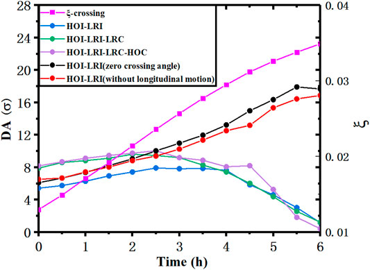
FIGURE 4. Evolutions of the averaged dynamic aperture (DA, in circles) and beam-beam tune shift parameter (squares) with time including emittance damping and particles burning-off. HOI, LRI, HOC and LRC denote head-on interaction, long-range interaction, head-on compensation and long-range compensation.
3.4 Electron Cloud Effects
3.4.1 Electron Cloud Formation
The electron cloud (EC) can cause beam instability. The build-up of accumulated photon electrons and secondary electrons was proved to be one of the most serious restrictions on collider luminosity in PEP II, KEKB, LHC [24, 25], and BEPC. The EC links together the motion of subsequent bunches and induces coupled bunch instability. It also leads to emittance blow-up and luminosity degradation [26, 27]. For the next-generation super proton colliders such as the SPPC with a bunch population higher than 1011 and a bunch spacing less than or equal to 25 ns, the EC effect will be critical for reaching the luminosity level of 1.6 × 1035 cm−2s−1.
There are three sources for the electron cloud: photon electrons, residual gas ionization and secondary electron emission. At a vacuum of about 1.3 × 10⁻⁷ Pa, the residual gas density is about 2 × 10¹³ m−3. With an ionization cross section of 2.0 Mb, the electrons produced by gas ionization can be ignored. The necessary condition for electron amplification is that the average secondary electron emission yield (SEY) exceeds one. Electron multipacting occurs if the electrons emitted from the wall reach the opposite side wall just prior to the arrival of the next bunch. The criterion
Most parameters in Table 4 are hardly changed if the bunch spacing is reduced, assuming that the average current is maintained: nb/Lsep = constant. However, as the bunch spacing is reduced, the parameter n changes rapidly. For a bunch spacing of 5 ns, n becomes larger than 1.0, and a large n corresponds to an almost electrostatic field that can support an electron cloud, but does not amplify it by multipacting. To produce a bunch spacing of 5 ns, a scheme applying the five-fold bunch splitting in MSS has been studied [16].
3.4.2 Electron Cloud Related Instabilities
The EC links oscillation between subsequent bunches and may lead to coupled bunch instability. The action propagated by the EC between subsequent bunches and the growth rate for the coupled bunch instability can be calculated [28, 29]. The coupled bunch instability can be damped by a feedback system. The EC also drives transverse emittance blow-up, which is very important at lower energy when the synchrotron radiation damping is very weak. For sufficiently long bunches, the single bunch instability manifests itself as strong-tail or transverse mode coupling instability (TMCI). Rough estimates on the TMCI electron density thresholds are summarized in Table 4. Some measures such as solenoid magnetic fields, clearing electrodes, or pipe coating should be taken to diminish the electron cloud.
The accumulated electron cloud as a focusing force on the proton beam will cause incoherent tune shift as the counterpart to space charge. A larger tune shift may lead to severe non-linear resonances. At the SPPC, with an average betatron function of about 145 m, the tune shift for an EC density of 1.0 × 10¹³ m−3 is estimated to be about 0.005 which cannot be ignored. Therefore, in the studies of lattice design and dynamic aperture, it will be necessary to consider the tune shift caused by the EC.
3.5 Beam Loss and Collimation
3.5.1 Beam Loss
Beam losses will be extremely important for safe operation in a machine like SPPC where the stored beam energy will be 9.1 GJ per beam. Beam losses can be divided into two classes, irregular and regular [30, 31]. Irregular beam losses are avoidable losses and are often the result of a misaligned beam or due to a fault in an accelerator element. A typical example is a trip of the RF, which causes loss of synchronization during acceleration and collisions. Vacuum problems also fall into this category. Such losses can be distributed around the machine. A well designed collimator system might collect most of the lost particles, but even a small fraction of the lost particles may cause problems at other locations. Regular losses are non-avoidable and localized in the collimator system or on other aperture limits. They will occur continuously during operation and correspond to the lifetime and transport efficiency of the beam in the accelerator. The lowest possible losses are set by various effects, e.g., Touschek effect, beam-beam interactions, collisions, transverse and longitudinal diffusion, residual gas scattering, halo scraping and instabilities [31]. At the SPPC, the main concerned beam loss mechanisms are listed below, and some of them have been studied in detail.
1) Touschek effect: This, also referred to as intra-beam scattering in the longitudinal plane, is caused by the scattering of charged particles within an individual bunch, and their subsequent loss. It is typically estimated by an average of the scattering rate around the ring [32].
2) Beam-beam interactions: Beam-beam interactions at the IPs produce collisions for physics experiments, but also elastic and inelastic scattering that will lead to emittance blow-up and beam loss [32, 33].
3) Transverse and longitudinal diffusion: Resonance crossings or unstable motion caused by unavoidable field errors and higher order multipoles of ring magnets can cause beam particles to leave the confined phase area and strike the machine aperture. Particles inside the dynamic aperture may also diffuse out from the core of the beam and into the unstable region, e.g., through intra-beam scattering, beam-gas scattering and beam-gas bremsstrahlung [32, 34].
4) Residual gas scattering: This includes inelastic beam-gas nuclear inelastic interactions (both quasi-elastic and diffractive), elastic beam-gas nuclear elastic interactions (both coherent and incoherent), and Coulomb scattering. These effects degrade the beam quality and can also cause immediate beam loss [31, 34].
5) Collimator tails: Collimation is done in both betatron and momentum cleaning insertions, and also as protective measures in other regions such as collision regions. Protons that pass close to, or are only partially stopped by the collimators, can be deflected, and must be intercepted by tertiary and even quaternary collimators. But there is always some inefficiency in these systems leaving tails, also known as “tertiary/quaternary beam halo” that can be lost in other locations in the ring [31, 35].
6) Collective instabilities: A beam becomes unstable when the moments of its distribution exhibit exponential growth (e.g., barycenters and standard deviations in different coordinates) which result in beam loss or emittance growth. There are a wide variety of mechanisms which may produce collective beam instabilities, with the most important ones being the electron cloud effect as described above and coupling impedance.
3.5.2 Collimation
For high-power or high stored-energy proton accelerators, halo particles might potentially impinge on the vacuum chambers and get lost. The radiation from the lost particles will trigger quenching of the superconducting magnets, generate unacceptable background in detectors, damage radiation-sensitive devices, and cause residual radioactivity that prevents hands-on maintenance. These problems can be addressed by collimation systems which confine the particle losses to specified locations where better shielding and heat-load transfer are provided. For high-energy proton-proton colliders with very high stored-energy in the beams, like SPPC, the situation is even more complicated, mainly because extremely high collimation efficiency is required. In addition, it is very difficult to collimate very high energy protons efficiently and the material for the collimators becomes a problem due to impedance and radiation resistance issues.
To illustrate the likely systems needed for the SPPC, we discuss first those used successfully in the LHC, even though it has lower beam energy and stored energy. The LHC uses 98 two-sided and 2 one-sided movable collimators, for a total of 396 degrees of freedom, which provide a four-stage collimation system to tackle 100 MJ of stored energy per beam [36, 37]. LHC is now upgrading the systems for the incoming operation at their design energy of 14 TeV (center-of-mass), and will do additional improvements for the high-luminosity upgrade (HL-LHC) [39]. Two warm interaction regions (IRs) or long straight sections are used to provide betatron collimation and momentum collimation, respectively. Both collimation systems use the sophisticated multi-stage collimation method [39].
With the multi-stage collimation method, the primary collimators of small thickness are the closest to the beam in the transverse phase space and will scatter the primary halo particles. They must be located at large β values to maximize the impact parameters and reduce the out-scattering probability. The secondary and sometime even tertiary collimators will intercept and stop part of the scattered particles; however, they also produce out-scattered particles, which are called secondary and tertiary beam halos. The absorbers will stop the showers from upstream collimators and the additional tertiary or quaternary collimators are used to protect the superconducting quadrupole triplets at the colliding interaction regions directly [37]. The introduction of the collimation system not only demands precious space in the rings, but also increases the coupling impedance, important for collective beam instabilities. However, even this performance is considered not sufficient to prevent the superconducting magnets quenching when the LHC will be upgraded to the HL-LHC with a stored energy up to about 700 MJ [38, 40]. By studying single diffractive effects (SDE) it was found that the problem arises from that the beam loss at the downstream dispersion suppression (DS) section of the betatron collimation insertion (IR7) becomes too important. Thus the LHC is considering to add additional collimators in the DS sections.
For SPPC, the stored energy in beam is as high as 9.1 GJ per beam, about 23 times that of the LHC at design energy. Therefore, for the same beam loss power, and to prevent frequent SC magnet quenching, the cleaning inefficiency at SPPC should be about 1/23 of that at the LHC. This means a cleaning inefficiency of only 3.0 × 10⁻⁶. Thus five-stage collimation systems for both betatron and momentum collimations are foreseen. Figure 5 shows the schematic for such a five-stage collimation system, where four stages are in a dedicated collimation section and the fifth is at the IPs to protect the detectors. To avoid the critical SDE which becomes more important at higher energy, we developed a novel concept by combining the betatron collimation and momentum collimation in a same long straight section [41]. In this way, the particles from the SDE at the betatron primary collimators can be cleaned by the momentum collimation system, and we can avoid warm collimators in the downstream DS sections. A chicane-like structure provides dispersion for momentum collimation. One of the two very long straight sections of about 4.3 km is used to host the collimation system, see Figure 6. To provide the required phase advance for the four-stage collimation, both dipoles and quadrupoles are superconducting magnets instead of traditionally used warm magnets. These cold quadrupoles are very different from those in the arcs, and they will be designed with enlarged apertures and lower pole strength (not higher than 8 T) with strong radiation shielding, somewhat comparable to the triplet quadrupoles used in the experiment insertions at the LHC. Simulations show that with all the measures taken the radiation is manageable [41]. To further reduce the particle losses in magnets from the SDE, some protective or passive collimators are also used. Figure 7 shows the simulated proton map in the collimation section. All the cold magnets are kept protected from quench.

FIGURE 5. Schematic for the five-stage collimation system at SPPC. The kicker and dump protection, which will operate in the cases of machine mal-functions, are a part of the entire machine protection system.
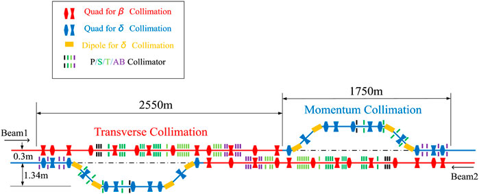
FIGURE 6. Layout of the collimation insertion. P/S/T/AB denote primary collimator, secondary collimator, tertiary collimator and absorber.
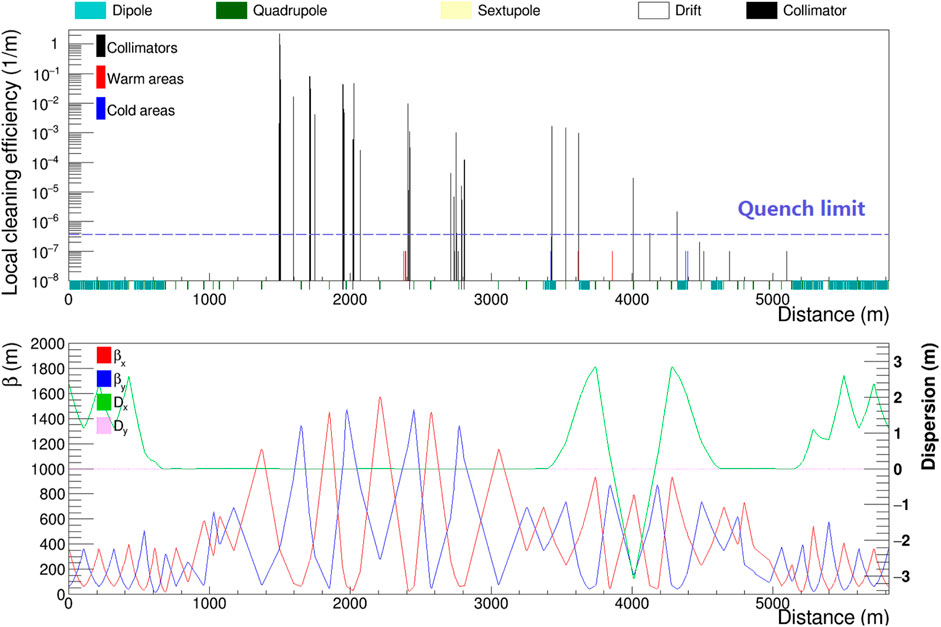
FIGURE 7. Proton loss map in the collimation insertion with an initial vertical halo distribution (upper) and the lattice (lower).
Besides the conventional method used at the LHC with primary scattering collimators and absorbers, other novel methods will be considered, including the one studied in CERN and FNAL with bent crystals [42, 43], and the one employing nonlinear magnets to enhance the collimation efficiency [44, 45].
4 Key Technical Systems
4.1 High-Field Superconducting Magnets
4.1.1 Requirements of the High-Field Magnets for SPPC
To bend and focus the high energy proton beams, SPPC needs thousands of high-field dipoles and quadrupoles installed around a tunnel of 100 km in circumference. The nominal aperture in these magnets is 50 mm. The field strength of the main dipoles is 12 T. A field uniformity of 10–4 should be attained up to 2/3 of the aperture radius. The magnets are designed to have two beam apertures of opposite magnetic polarity within the same yoke (2-in-1 or twin aperture) to save space and cost. The currently assumed distance between the two apertures in the main dipoles is 300 mm, but this could be changed based on the detailed design optimization to control the cross-talk effect between the two apertures, and with consideration of overall magnet size. The outer diameter of the main dipole and quadrupole magnets should not be larger than 650 mm, so that they can be placed inside cryostats having an outer diameter of about 1,100 mm. The total magnetic length of the main dipole magnets is about 65.4 km out of the total circumference of 100 km. If the length of each dipole magnet is about 15 m, then about 4,360 dipole magnets are required. High field gradient quadrupoles for SPPC are divided into the following three groups:
1) Type A, at the IPs with single aperture, diameter: 60 mm, pole-tip field: 12 T;
2) Type B, in the matching section with twin aperture, diameter: 60 mm, pole-tip field: 12 T;
3) Type C, in the arcs with twin aperture, diameter: 50 mm, pole-tip field: 12 T.
The inner triplet quadrupoles very close to the IPs are supposed to require very special design to tackle very high radiation in the region.
4.1.2 Current Status of High-Field Accelerator Magnet Technology
One of the most challenging technologies for SPPC is the development of the high field superconducting magnets. Development of superconducting dipole magnets started more than 30 years ago in US laboratories [46, 47]. All the superconducting magnets used in present accelerators are made with NbTi. These magnets work at significantly lower field than the required 12 T (14 T is really required to have an operational margin), e.g., 3.5 T at 4.2 K at RHIC and 8.3 T at 1.8 K at LHC. As shown in Figure 8, the critical “engineering” current density JE of most superconductor wires falls rapidly with the magnetic field. A reasonable design of accelerator magnets requires that the average JE of the cable should be above 500 A/mm2 at the desired field. This criterion suggests that it should be possible to develop a dipole with Nb3Sn of 15–16 T, but the cost of massive production magnets is not promising even in 15–20 years from now. Thus one has to look for alternate superconductors. Fortunately, the advent of High-Temperature Superconductors (HTS) such as YBCO, BI-2212 and BI-2223, in contrary to Low-Temperature Superconductors (LTS) such as NbTi, MgB2 and Nb3Sn, whose current carrying capacity decreases only slowly with field (see Figure 8), should allow magnets with much higher magnetic fields and much reduced cost in longer term. Among different type of HTS, iron-based HTS has special advantage for isotopic field property and greater potential in future cost reduction. The SPPC strategy is to build iron-based HTS magnets of a modest field of 12 T in Phase-I, and to keep the ultimate upgrading phase to 20–24 T to boost the center-of-mass energy to 125–150 TeV.
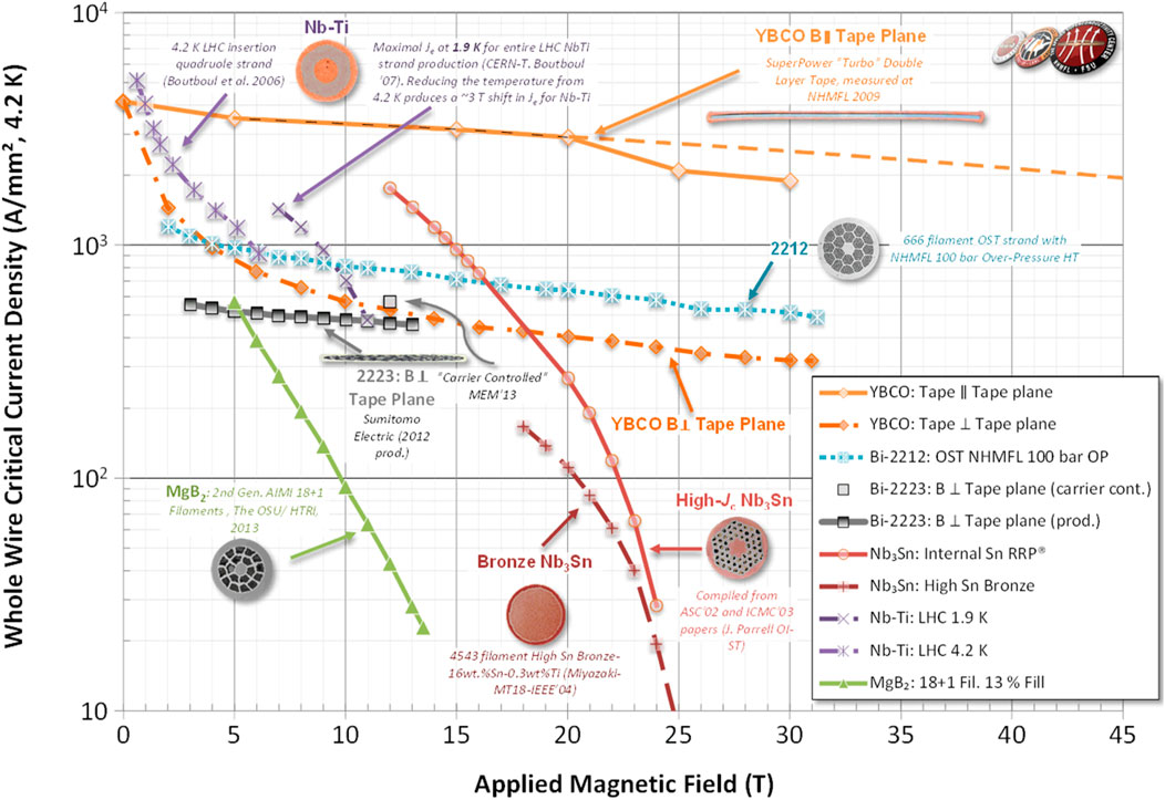
FIGURE 8. Whole wire critical current density of main superconductors at 4.2 K [48], among them YBCO, BI-2212 and BI-2223 belonging to HTS and NbTi, MgB2 and Nb3Sn belonging to LTS.
Cryogenic is a very costly system related to superconducting magnets. For LTS technology, operation at 1.8 K, instead of 4.2 K, is another option worth study. The quantities of NbTi and Nb3Sn, and their cost, would be reduced, but the cryogenic cost would be greater. An optimization design with 1.8 K solution is required before to have the comparison with the 4.2 K solution on the global cost. Another factor affecting the choice of the temperature is the vacuum design in which the pumping speed is dependent on the temperature.
4.1.3 Development Plan of the High-Field Magnets for SPPC
As mentioned above, the current state-of-the-art magnet technology does not meet the requirements of SPPC, both in technology maturity and cost effectiveness. On the other hand, SPPC is a long-term project aiming for the period of 15–20 years or even longer, thus there is plenty of time for technology development. A roadmap has been established to develop high-field magnet technology in China, especially the one with iron-based HTS superconducting magnets. There are strong common interests from different sectors to develop iron-based HTS superconductors. A consortium consisting of many research institutions and industrial enterprises in China has been formed to develop the technology from basic research to different applications. A few development stages are needed from earlier R&D prototypes of lower field and small aperture, to full-size magnets and to mass production magnets. In the meantime, other HTS and LTS magnet technology will also be studied in parallel, in order to master the magnet structure design, field quality control, quench protection, etc.
4.2 Vacuum and Beam Screen
4.2.1 General Vacuum Considerations
SPPC has three vacuum systems: insulation vacuum for the cryogenic system, beam vacuum for the low-temperature sections, and beam vacuum for the chambers in the room-temperature sections.
4.2.1.1 Insulation Vacuum
The aim here is only to avoid convective heat transfer and there is no need for high vacuum. The room-temperature pressure in the cryostats before cool-down does not have to be better than 10 Pa. Then, so long as there is no significant leak, the pressure will stabilize around 10–4 Pa, when the cryostat is at cold conditions. As a huge volume of insulation vacuum is needed at SPPC, careful design is needed to reduce the cost.
4.2.1.2 Beam Vacuum in Cold Sections
In interaction regions or around experiments where superconducting quadrupoles are used, the vacuum has to be very good (less than 1013 H2 per m3) to avoid creating background in the detectors. But the beams are straight here and there is relatively little synchrotron radiation.
In the arcs, the requirement is based on the beam lifetime, which depends on the nuclear scattering of protons on the residual gas [3]. To ensure a beam lifetime of about 100 h, the equivalent hydrogen gas density should be below 1015 H2 per m3. The problem here is the huge synchrotron radiation power. If allowed to fall directly on the magnet bore at the magnet temperature of 4.2 K or 1.8 K, the wall power needed to remove it would be grossly too high. It has to be intercepted on a beam screen, which works at a higher temperature, e.g. 40–60 K and is located between the beam and cold bore (see below). This screen, at such a temperature, will desorb hydrogen gas, particularly if it is directly exposed to synchrotron radiation. The space outside the screen will be cryopumped by the low temperature of the bore. Slots must be introduced in the shield to pump the beam space. However, if the core is at 4.2 K, the pumping speed of H2 is low, thus one may need to use other auxiliary methods, such as cryosorbers used at LHC [49].
4.2.1.3 Beam Vacuum in Warm Sections
The warm regions are used to house the beam collimation, injection, and extraction systems. They use warm magnets or isolated superconducting magnets to tackle with the inevitable beam losses in these locations. They have difficult vacuum pumping requirements due to desorption from the beam losses. The pumping technique with NEG (Non Evaporable Getter) coating is probably required. At least these sections are of limited overall length or much shorter than the cold sections, thus the caused trouble can be managed.
4.2.1.4 Vacuum Instability
Vacuum instability issues need further investigation [50].
4.2.2 Beam Screen
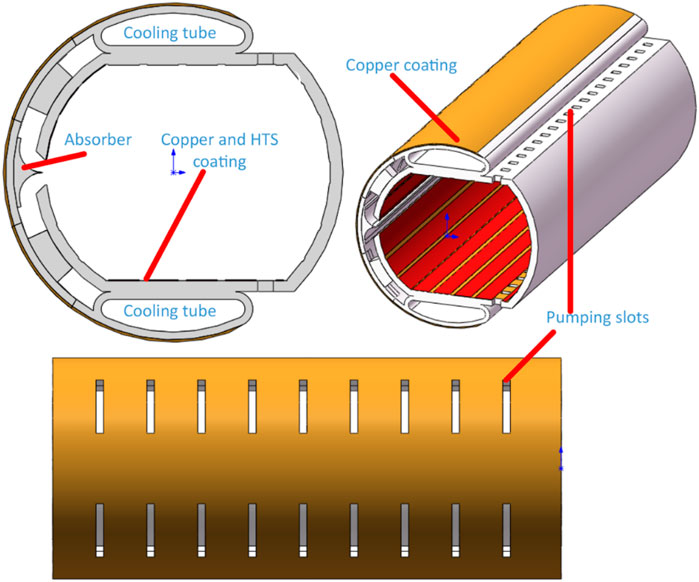
The main function of a beam screen is to shield the cold bore of the superconducting magnets from synchrotron radiation [51]. At SPPC, synchrotron radiation is especially strong because of the very high beam energy and high magnetic field in the arc dipoles. The estimated SR power is about 12.8 W/m per aperture in the arc dipoles. This is much higher than the 0.22 W/m at LHC [52], and greatly increases the difficulty of the beam screen design. The beam screen design should be a compromise to extract the heat load, minimize the occupation of the bore aperture, provide vacuum pumping, reduce coupling impedance and electron cloud, etc. An ideal design of the beam screen might separate the two principal functions—heat load transfer and vacuum pumping, which has been studied at FCC-hh [53] and also at SPPC [54]. The screen itself which encircles the beam, with the slot on the outer side would be run at a relatively lower temperature to control the impedance, while the absorption structures which synchrotron radiation penetrates through the slot would be at a higher temperature to minimize the wall power needed to extract the synchrotron radiation power.
The operating temperature of the screen must be high enough to avoid excessive wall power needed to remove the heat. But not too high to avoid excessive resistivity of the high-temperature superconducting material or copper coating on its inside surfaces, leading to excessive impedance, and to avoid radiating too much power on to the bore at 4.2 K or 1.8 K.
The design must satisfy requirements of vacuum stability, mechanical support, influence on beam dynamics and refrigeration power. Figure 9 shows the schematic for the beam screen at SPPC. The main challenges for designing the beam screen are: the working temperature should be balanced between higher temperature for wall power economy due to very high synchrotron radiation load and lower temperature for limiting the impedance; a proper beam screen structure occupies less possible aperture, has sufficient mechanical strength, shields synchrotron radiation from feeding photo-electrons in the beam path, and has a good vacuum pumping; magnet quenches have important impact on the mechanical strength of the beam screen [55], thus the materials for the base (e.g., stainless steel) and coated layers (e.g., YBCO and/or copper) are key factors in balancing the need of low impedance.
4.3 Other Technical Challenges
Besides the two key technologies described above, high-field magnets and vacuum/beam screens, there are other important technologies requiring development in the coming decade in order to build SPPC. Among them are the machine protection system that requires extremely high efficiency collimation, and a very reliable beam abort system. These are important for dumping the huge energy stored in the circulating beams, when a magnet quenches, or another abnormal operating condition occurs. If the extraction system has to be installed in a relatively short straight section, one has to develop more powerful kickers.
A complicated feedback system is required to maintain beam stability. The beam control system also controls emittance blow-up in the collider rings which is important for controlling beam-beam induced instabilities and for leveling the integrated luminosity.
Beam loss control and collimation in the high-power accelerators of the injector chain pose additional challenges. A proton RCS of 10 GeV and a few MW are still new to the community, and needs special care. The gigantic cryogenic system for magnets, beam screens and RF cavities also needs serious consideration.
5 Injector Chain
The injector chain by itself is an extremely large accelerator complex. To reach the beam energy of 2.1 TeV required for injection into the SPPC, we require a four-stage acceleration system, with energy gains per stage between 8 and 18. It not only accelerates the beam to the energy for injection into the SPPC, but also prepares the beam with the required properties such as the bunch current, bunch structure, and emittance, as well as the beam fill period.
The four stages are shown in Figure 10, with some more parameters given in Table 5. The lower the stage, the higher the repetition rate is. The p-Linac is a superconducting linac with a repetition rate of 50 Hz. The p-RCS is a rapid cycling synchrotron with a repetition rate of 25 Hz. The MSS has a relatively lower repetition rate of 0.5 Hz. The SS, which is based on superconducting magnets with maximum dipole field of about 8 T, is even slower. The higher repetition rates for the earlier stages help reduce the SS cycling period and thus the overall SPPC beam fill time. For easier maintenance and cost efficiency, as well as the physics programs, the first three stages will be built in a relatively shallow underground level, e.g., −15 m, whereas the SS with a much larger circumference will be built in the same level as the SPPC or from −50 m to −100 m.
As shown in Table 5, for the SPPC, the different stages are needed for only fractions of the time. They could operate with longer duty cycles, or continuously, to provide high-power beams for other research applications, when they do not serve the SPPC collision. As the present bunch population at the SPPC is limited mainly by the SR power, the accelerators of the injector chain have the potential to load more accumulated particles in a pulse or deliver higher beam power for their own diverse applications when not serving the SPPC. Certainly this capability is also very useful for the future SPPC upgrading.
For such a complex injector system, it may take about 10 years to build and commission stage-by-stage. Thus hopefully the construction of the injector accelerators can be started several years earlier than the SPPC, and this means that it overlaps with the CEPC physics operation.
5.1 p-Linac
Superconducting linacs have undergone tremendous development [56] in the last 2 decades and will presumably make even more progress in the next decade. Hence we have adopted a design of 1.2 GeV in energy and 50 Hz in repetition rate for the p-Linac. The continuous beam power is 1.63 MW. At least half of this could be available for other applications.
5.2 p-RCS
The continuous beam power from p-RCS is 3.4 MW. Only one other proton driver study (for a future Neutrino Factory) has performance close to this [57]. The high repetition rate of 25 Hz will shorten the beam filling time in the MSS. Only a fraction of this power is needed to fill the MSS. Thus most of the beam pulses from the p-RCS could be used for other physics programs. The p-RCS will use mature accelerator technology but be on a larger scale than existing rapid-cycling proton synchrotrons. High-Q ferrite loaded RF cavities are planned to provide very high RF voltage of about 3 MV, and the RF frequency swing of 36–40 MHz is suitable to provide the bunch spacing of 25 ns needed by SPPC.
5.3 MSS
The MSS has beam power similar to the p-RCS but with much higher beam energy and much lower repetition rate. The SPS at CERN and the Main Injector at Fermilab are two good examples for its design. But due to much higher beam power, the beam loss rate must be more strictly controlled. The same RF system as in the p-RCS is planned, but a more sophisticated multi-harmonic RF system is reserved for the future bunch splitting to provide 5-ns bunch spacing. Certainly, the beam from the MSS will find additional physics programs other than only being the injector for the SS.
5.4 SS
The SS will use superconducting magnets similar to those used at the LHC, but with a higher ramping rate. Here, we do not need to consider synchrotron radiation because of the much lower energy. There are no apparent critical technical risks in building the SS. It is still unclear if the beam from the SS can find its own physics programs besides being the SPPC injector.
A dedicated heavy-ion linac (i-Linac) together with a new heavy-ion synchrotron (i-RCS), in parallel to the proton linac/RCS, is needed to provide heavy-ion beams at the injection energy of the MSS, with a beam rigidity of about 36 Tm which is the same as the proton beam of 10 GeV.
6 Discussions and Conclusion
A design concept for a future proton-proton collider of 75 TeV in center-of-mass energy has been studied, aiming to achieve high precision in measuring the properties of the Higgs boson and probe the high energy frontier in search for new physics beyond the standard Model. Both the physics potentials and the accelerator scheme are outlined here. The machine performance and key issues on accelerator physics and technology are addressed. Although the CEPC-SPPC project is intended to be hosted by China, the study presented here is totally site-independent.
There are many uncertainties in the physics goals, since the project is supposed to be built in 20 years from now. It is already under discussion how to make a compromised layout to accommodate both CEPC and SPPC in the same tunnel.
On the one hand, the progress in general accelerator technology during the next 2 decades may make those extremely challenging accelerator designs feasible. On the other hand, international efforts to overcome the technical obstacles for building such a machine should be pursued. Fortunately, with the ongoing efforts for the SPPC and FCC-hh projects as a driving force, an international community has already been established to tackle key technical issues such as high-field superconducting magnets, cryogenic beam vacuum or beam screen, beam collimation, etc.
Author Contributions
JT reviews the study that has been carried out by the SPPC study group since 2014.
Funding
The work is supported by National Natural Science Foundation of China (Projects 11575214, 12035017).
Conflict of Interest
The author declares that the research was conducted in the absence of any commercial or financial relationships that could be construed as a potential conflict of interest.
Publisher’s Note
All claims expressed in this article are solely those of the authors and do not necessarily represent those of their affiliated organizations, or those of the publisher, the editors and the reviewers. Any product that may be evaluated in this article, or claim that may be made by its manufacturer, is not guaranteed or endorsed by the publisher.
Acknowledgments
The author would like to thank all the international experts who have provided us with useful comments during the reviews and on other occasions. Special gratitude goes to the following persons for their contributions to the study: J. Scott Berg (LBNL), Weiping Chai (IMP), Fusan Chen (IHEP), Nian Chen (USTC), Yukai Chen (IHEP), Weiren Chou (IHEP/FNAL), Jianping Dai (IHEP), Haiyi Dong (IHEP), Angeles Faus-Golfe (LAL), Pingping Gan (PKU), Jie Gao (IHEP), Yuanyuan Guo (IMP), Ramesh Gupta (BNL), Tao Han (Pitt), Yang Hong (IHEP), Alexander Krasnov (BINP), Yongbin Leng (SINAP), Guangrui Li (THU), Peng Li (IMP), Zhihui Li (SCU), Baiqi Liu (IHEP), Yudong Liu (IHEP), Xinchou Lou (IHEP/UTD), Yuanrong Lu (PKU), Qing Luo (USTC3, Ernie Malamud (FNAL), Lijun Mao (IMP), James Molson (LAL), Robert B. Palmer (BNL), Quanling Peng (IHEP), Yuemei Peng (IHEP), Qing Qin (IHEP), Stefano Redaelli (CERN), Manqi Ruan (IHEP), GianLuca Sabbi (LBNL), Frank Schmid (CERN), Tanaji Sen (FNAL), Feng Su (IHEP), Shufang Su (UArizona), Diktys Stratakis (BNL), Baogeng Sun (USTC), Meifen Wang (IHEP), Jie Wang (USTC), Liantao Wang (UChicago), Lijiao Wang (IHEP), Xiangqi Wang (USTC), Yifang Wang (IHEP), Yong Wang (USTC), Qingzhi Xing (THU), Qingjin Xu (IHEP), Hongliang Xu (USTC), Wei Xu (USTC), Holger Witte (BNL), Yingbing Yan (SINAP), Yongliang Yang (USTC), Jiancheng Yang (IMP), Ye Yang (THU), Youjin Yuan (IMP), Bo Zhang (USTC), Linhao Zhang (IHEP), Yuhong Zhang (JLAB), Shuxin Zheng (THU), Kun Zhu (PKU), Zian Zhu (IHEP), Ye Zou (IHEP/USTC). Most of the materials were presented in the CEPC-SPPC Preliminary Conceptual Design Report and CEPC Conceptual Design Report [2]. Figures 3 and 4 are from an unpublished paper (Beam-beam effects and mitigation in a future proton-proton collider, L.J. Wang et al.).
References
1. Hinchliffe I, Kotwal A, Mangano ML, Quigg C, Wang LT. Luminosity Goals for a 100-TeV Pp Collider. arXiv:1504.06108 (2015).
2.The CEPC-SPPC Study Group. CEPC-SPPC Preliminary Conceptual Design Report. In: 2015: The CEPC Study Group, CEPC Conceptual Design Report: Volume 1 - Accelerator. arXiv:1809.00285 [physics.acc-ph], IHEP-CEPC-DR-2015-01 (2018). p. 01.
3. Brüning O, Collier P, Lebrun P, Myers S, Ostojic R, Poole J, et al. LHC Design Report. In: The LHC Main Ring. CERN (2004). p. 003.
5.SSC Central Design Group. Conceptual Design of the Superconducting Super Collider. SSC-SR-2020 (1986).
6.The VLHC Design Study Group. Design Study for a Staged Very Large Hadron Collider. Fermilab TM-2149 (2001).
7.E Todesco, and F Zimmermann, editors. Proc. Of EuCARD AccNet-EuroLumi Workshop: The Proceedings EuCARD AccNet-EuroLumi Workshop: The High-Energy Large Hadron Collider, ‘HE-LHC-2010’. Report CERN-2011-003 (2011). p. 14–6.
11. Benedikt M. Study Status & Parameter Update, In: FCC Week; 2016 April 11–15; Rome, Italy (2016). p. 11–5.
12. Zhang LH, Tang JY, Hong Y, Chen YK, Wang LJ. Optimization of Design Parameters for SPPC Longitudinal Dynamics. J Inst (2021) 16:P03035. doi:10.1088/1748-0221/16/03/p03035
14. Bruening O. Accelerator Physics Requirements at Commissioning, In: 11th Workshop of the LHC, CERN-SL-2001-003; 2001 Jan 15–19; Chamonix, France (2001).
15. Wang LJ, Tang JY. Luminosity Optimization and Leveling in the Super Proton-Proton Collider. Radiat Detect Technol Methods (2021) 5:245–54. doi:10.1007/s41605-020-00233-6
16. Zhang L, Chen M, Tang J. Multifold bunch Splitting in a High-Intensity Medium-Energy Proton Synchrotron. Results Phys (2022) 32:105088. doi:10.1016/j.rinp.2021.105088
17. Shiltsev V. Beam-beam Effects in a 100 TeV P-P Future Circular Collider. Washington DC: presentation at FCC Week 2015 (2015).
18. Ohmi K, Dominguez O, Zimmermann F. Beam Beam Studies for the High-Energy LHC”. CERN Yellow Report CERN-2011-003 (2011). p. 93–8.
19. Sen T. Observations and Open Questions in Beam-Beam Interactions. ICFA Beam Dyn Newslett (2010) 52:14–32.
20. Shiltsev V. High Luminosity Operation, Beam-Beam Effects and Their Compensation in TEVATRON. In: Proceedings of EPAC08. IEEE (2008). p. 951–5.
21. Papotti G, Buffat X, Herr W, Giachino R, Pieloni T. Observations of Beam-Beam Effects at the LHC. arXiv:1409.5208 (2016).
22. Wang LJ. Study on Luminosity of Super Proton-Proton Collider. [PhD thesis]. University of Chinese Academy of Sciences (Institute of High Energy Physics, CAS) (2021).
23. Alexahin Y, Grote H, Herr W, Zorzano MP. Coherent Beam-Beam Effects in the LHC. LHC Project Rep (2001) 469:1.
24. Miguel A. Furman, “The Electron-Cloud Effect in the Arcs of the LHC”. LHC Project Rep (1998) 180:1.
26. Arduini G, Baglin V. Present Understanding of Electron Cloud Effects in the Large Hadron Collider. In: PAC 2003. Portland, Oregon, USA: IEEE (2003). p. 12–6.
27. Benedetto E, Schulte D, Zimmermann F, Rumolo G. Simulation Study of Electron Cloud Induced Instabilities and Emittance Growth for the CERN Large Hadron Collider Proton Beam. Phys Rev ST Accel Beams (2005) 8:124402. doi:10.1103/physrevstab.8.124402
28. Ohmi K. Beam-Photoelectron Interactions in Positron Storage Rings. Phys Rev Lett (1995) 75:1526–9. doi:10.1103/physrevlett.75.1526
29. Zimmermann F. A Simulation Study of Electron-Cloud Instability and Beam-Induced Multipacting in the LHC. LHC-PR-95, SLAC-PUB-7425 (1997).
30. Holzer EB, Dehning B, Effnger E, Emery J, Grishin V, Hajdu C, et al. Beam Loss Monitoring for LHC Machine Protection. Phys Proced (2012) 37:2055–62. doi:10.1016/j.phpro.2012.04.110
31. Drozhdin AI, Mokhov NV, Striganov SI. Beam Losses and Background Loads on Collider Detectors Due to Beam-Gas Interactions in the LHC. In: Proceedings of PAC09. Vancouver, BC, Canada: IEEE (2009). p. 2549–51.
32. Wittenburg K. Beam Loss Monitoring and Control. In: Proceedings of EPAC 2002. Paris, France: IEEE (). p. 109–13.
33. Bruce R. Beam Loss Mechanisms in Relativistic Heavy-Ion Colliders. Doctoral Thesis, CERN-THESIS-2010-030 (2010). p. 39–45.
34. Mead DJ. The Measurement of the Loss Factors of Beams and Plates with Constrained and Unconstrained Damping Layers: A Critical Assessment. J Sound Vibration (2007) 300:744–62. doi:10.1016/j.jsv.2006.08.023
35. Roderik Bruce D. Off-momentum Collimation and Cleaning in the Energy Ramp in the LHC. CERN-THESIS-2013-159 (2013). p. 17–23. Doctoral Thesis.
36. Redaelli S. Operational Performance of the LHC Collimation. In: Proc. Of HB2010. Morschach, Switzerland: IEEE (2010). p. 395–9.
37. Salvachua B. Cleaning Performance of the LHC Collimation System up to 4 TeV. In: Proc. Of IPAC2013. Shanghai, China: IEEE (2013). p. 1002–4.
38. Serluca M, Appleby RB, Molson J, Barlow RJ, Rafique H, Toader A. Hi-lumi LHC Collimation Studies with MERLIN Code. In: Proc. Of IPAC2014. Dresden, Germany: IEEE (2014). p. 784–7.
39. Catalan-Lasheras N. Transverse and Longitudinal Beam Collimation in a High-Energy Proton Collider (LHC). [PhD thesis]. Zaragoza (1998).
40. Marsili RBA, Redaelli S. Cleaning Performance with 11T Dipoles and Local Dispersion Suppressor Collimation at the LHC. In: Proc. Of IPAC14. Dresden, Germany: IEEE (2014). p. 170–3.
41. Yang J-Q, Zou Y, Tang J-Y. Collimation Method Studies for Next-Generation Hadron Colliders. Phys Rev Acc Beams (2019) 22:023002. doi:10.1103/physrevaccelbeams.22.023002
42. Scandale W, Arduini G, Assmann R, Bracco C, Gilardoni S, Ippolito V, et al. First Results on the SPS Beam Collimation with Bent Crystals. Phys Lett B (2010) 692:78–82. doi:10.1016/j.physletb.2010.07.023
43. Zvoda V. Advanced Bent crystal Collimation Studies at the Tevatron (T-980). In: Proc. Of PAC2011. New York, USA: IEEE (2011). p. 73–5.
44. Guo Z, Tang J-Y, Yang Z, Wang X-Q, Sun B. A Novel Structure of Multipole Field Magnets and Their Applications in Uniformizing Beam Spot at Target. Nucl Instr Methods Phys Res Section A: Acc Spectrometers, Detectors Associated Equipment (2012) 691:97–108. doi:10.1016/j.nima.2012.06.048
45. Zou Y, Tang J, Yang J. Resonant Slow Extraction in Synchrotrons Using Anti-symmetric Sextupole fields. Nucl Instr Methods Phys Res Section A: Acc Spectrometers, Detectors Associated Equipment (2016) 830:150–62. doi:10.1016/j.nima.2016.05.081
46. Dietderich DR, Godeke A. Nb3Sn Research and Development in the USA - Wires and Cables. Cryogenics (2008) 48:331–40. doi:10.1016/j.cryogenics.2008.05.004
47. Gupta RC. A Common Coil Design for High Field 2-in-1 Accelerator Magnets. In: Proc. Of PAC 1997. Vancouver, Canada: IEEE (1997). p. 3344–6.
48. Lee P. A Comparison of Superconductor Critical Currents. Whole wire critical current density values for long-length superconductors (nationalmaglab.org) (2021)
49. Anashin VV. The Vacuum Studies for LHC Beam Screen with Carbon Fiber Cryosorber. In: Proc. Of APAC2004. Gyeongju, Korea: IEEE (2004). p. 329–31.
50. Gröbner O. Vacuum Issues for an LHC Upgrade. In: 1st CARE-HHH-APD Workshop on Beam Dynamics in Future Hadron Colliders and Rapidly Cycling High-Intensity Synchrotrons. CERN (2004).
52. Baglin V. Synchrotron Radiation Studies of the LHC Dipole Beam Screen with Coldex. In: Proc. Of EPAC 2002. Paris, France: IEEE (2002). p. 2535–7.
53. Krkotić P, Niedermayera U, Boine-Frankenheim O. High-temperature Superconductor Coating for Coupling Impedance Reduction in the FCC-Hh Beam Screen. Nucl Instru Meth A (2018) 895:56–61.
54. Gan P, Zhu K, Fu Q, Li H, Lu Y, Easton M, et al. Design Study of an YBCO-Coated Beam Screen for the Super Proton-Proton Collider Bending Magnets. Rev Scientific Instr (2018) 89:045114. doi:10.1063/1.5026932
55. Rathjen C. Mechanical Behaviour of Vacuum Chambers and Beam Screens under Quench Conditions in Dipole and Quadrupole fields. In: Proc. Of EPAC2002. Paris, France: IEEE (2002). p. 2580–2.
56. Ostroumov P, Gerigk F. Superconducting Hadron Linacs. In: AW Chao, and W Chou, editors. Review of Accelerator Science and Technology. Singapore: World Scientific Publishing (2013). doi:10.1142/s1793626813300089
Keywords: proton-proton collider, physics beyond standard model, center-of-mass energy, luminosity, iron-based superconducting magnets
Citation: Tang J (2022) Design Concept for a Future Super Proton-Proton Collider. Front. Phys. 10:828878. doi: 10.3389/fphy.2022.828878
Received: 04 December 2021; Accepted: 08 February 2022;
Published: 02 March 2022.
Edited by:
Vladimir Shiltsev, Fermilab (DOE), United StatesReviewed by:
Alessandro Tricoli, Brookhaven National Laboratory (DOE), United StatesYunhai Cai, Stanford University, United States
Copyright © 2022 Tang. This is an open-access article distributed under the terms of the Creative Commons Attribution License (CC BY). The use, distribution or reproduction in other forums is permitted, provided the original author(s) and the copyright owner(s) are credited and that the original publication in this journal is cited, in accordance with accepted academic practice. No use, distribution or reproduction is permitted which does not comply with these terms.
*Correspondence: Jingyu Tang, dGFuZ2p5QGloZXAuYWMuY24=
 Jingyu Tang