 Xuepeng Sun
 Shangkun Shao1,2
 Tianyu Yuan
95% of researchers rate our articles as excellent or good
Learn more about the work of our research integrity team to safeguard the quality of each article we publish.
Find out more
ORIGINAL RESEARCH article
Front. Phys. , 04 May 2022
Sec. Optics and Photonics
Volume 10 - 2022 | https://doi.org/10.3389/fphy.2022.821549
This article is part of the Research Topic High-precision EUV and X-ray Optics for Advanced Photon Source Facilities View all 10 articles
Monocapillary x-ray lenses (MXRLs) are mostly used as condensers in full-field transmission x-ray microscopy (TXM) based on synchrotron radiation or laboratory x-ray tubes. The performance of the condenser has a significant impact on the imaging quality of the TXM. In this paper, a procedure for the characterization of the MXRL as a condenser is presented. The procedure mainly includes two parts: optical measurement and x-ray tests. From the test results of the characterization procedure, it can be seen that a relatively high-performance condenser can be screened out from a series of MXRLs drawn by an electric furnace. This is also fed back to the manufacturing process, and therefore, the technology of manufacturing the condenser can be gradually optimized. Moreover, the method of characterizing the performance of the condenser designed for synchrotron radiation TXM by laboratory x-ray tubes is proposed to be used in this procedure, which effectively reduces the manufacturing time of high-performance condensers for synchrotron radiation TXM.
Full-field transmission x-ray microscopy (TXM) is a powerful technique to observe the spatial structure of complex samples at nanoscale. TXM has a similar structure to visible light or electron microscopy. The resolution of TXM is superior to visible light microscopy because of the shorter wavelength of x-rays than visible light. Moreover, the powerful penetrating ability of x-rays enables TXM to nondestructively and three-dimensionally (3D) image complex structures compared to the either opaque to visible light microscopy or those that are too thick to be penetrated by electron microscopy. In the past decade, with the development of highly efficient x-ray optics and powerful x-ray sources, TXM working on the hard x-ray regime has been built at many synchrotron radiation facilities and in conventional laboratories using portable sources [1–9]. Besides, ZEISS in Germany offers commercial TXM, with a resolution down to 50 nm (ZEISS Xradia 800 Ultra). Because of its superior ability to nondestructively explore the internal structure of optically opaque solids with submicron resolution, TXM plays an important role in research in the fields of biology, medicine, minerals, and materials science [10–14].
The precision fabricated zone plate and the condenser are the key optical components of a TXM system. In the system, the zone plate works as an objective lens that receives the propagated image of the sample and produces a magnified image on a charge-coupled device (CCD) camera. TXM that has a zone plate as an objective lens needs a condenser to focus the x-ray beam onto the sample and increase the flux density while matching the numerical aperture (NA) with the zone plate [15]. So far, four main kinds of condenser optics for TXM have been reported in the studies: a zone plate, a multilayer mirror, a Kirkpatrick–Baez mirror, and a monocapillary x-ray lens (MXRL) [15–20]. The operating principle of the zone plate and the multilayer mirror confirms that they have a limited bandwidth, which is inconvenient for TXM to image at multiple wavelengths. In practice, to match the NA with the zone plate as an objective lens, the zone plate as a condenser is required to have a large diameter with a high number of zones and a small zone width, which is too difficult to manufacture, especially for hard x-rays. In addition, both types suffer from low efficiency, especially when used in TXM based on laboratory x-ray sources. Kirkpatrick–Baez mirrors and MXRLs based on total reflection are achromatic focusing optics. They have advantages such as being efficient, rugged, and achromatic, which is suitable for TXM systems. However, the illumination from the Kirkpatrick–Baez mirror is asymmetric, which generally generates inferior images when used in absorption contrast imaging and is not suitable for Zernike phase contrast imaging [21]. Besides the advantages of MXRLs mentioned above, they are symmetric, are easy to be aligned, and have a wide NA and bandwidth. This is clearly superior to other condensers used for TXM. In addition, MXRLs show good performance in focusing photons in the energy range of 5–25 keV. So far, a majority of tabletop and synchrotron hard x-ray TXM has chosen MXRL as the condenser. Figure 1 shows the schematic diagram of the TXM system based on the capillary condenser.
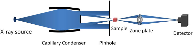
FIGURE 1. Schematic diagram of the TXM system based on the capillary condenser.
Ellipsoidal or parabolic MXRLs used in tabletop and synchrotron TXM are drawn using an optical fiber drawing machine as shown in Figure 2. A straight raw glass tube with a fixed inner and outer diameter is placed in the heating furnace along its axle line, which ensures the raw glass tube is heated evenly in the furnace. The heating furnace is set at a certain temperature to maintain the glass tube in a softened state. The shape of the MXRL is formed by controlling the speed of the puller and holder, which is attached to a linear stepper motor and utilized to feed the raw tube into the heating furnace. The embryo tube that contains the desired MXRL takes shape between the heating furnace and the puller. To obtain a high-performance MXRL for TXM, characterizing the performance of the MXRL is an inevitable choice that can not only select the most appropriate MXRL as the condenser in the TXM system but also facilitate the parameter optimization of the optics during the capillary pulling process. The characterization procedure of the MXRL mainly includes optical measurement and x-ray tests. According to the previous studies [22], the optical measurement of the embryo tube provides the outer profile accurately, and the inner profile is calculated from the fixed ratio of the inner to outer profiles (the ID/OD ratio). However, there are some variations in the ID/OD ratio with regard to fabrication conditions, such as the capillary material, the temperature of the furnace, and the speed of the puller and holder. Therefore, optical measurement can only roughly assess the quality of the optics. In this paper, the measured characterization procedure of a certain designed MXRL as a condenser for TXM of the Shanghai Synchrotron Radiation Facility (SSRF) was presented. The MXRL was cut apart to measure the inner diameter so that a more accurate ID/OD ratio can be obtained. After cutting, the performance of the MXRL as a condenser was more intuitively tested using the x-ray source.
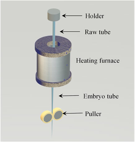
FIGURE 2. Schematic diagram of the MXRL drawing using an optical fiber drawing machine.
Table 1 lists the main parameters of the designed MXRL used as an example to demonstrate the condenser characterization procedure proposed in this study. In order to cut the designed MXRL from the embryo tube, a light microscope (LS-7030M, Keyence, Japan) with a motorized X stage as shown in Figure 3 was used to measure the outer profile of the embryo tube. The detection precision and the diameter detectable range of the light microscope are ± 2 μm and 0.3–30 mm, respectively. The measurement step of the embryo tube is 200 μm.
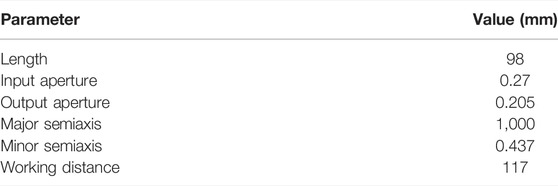
TABLE 1. Main parameter of the designed MXRL.
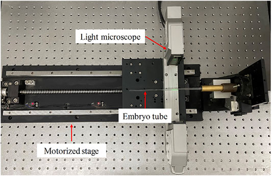
FIGURE 3. Photograph of the optical test platform based on a light microscope.
Differently to the method used by Huang and Bilderback, in which the inner diameter (ID) is calculated by the constant ID/OD ratio of the embryo tube, varying ratios of OD/ID as shown in Figure 4A were used to infer the inner profile of the embryo tube [22]. In our manufacturing process, it was discovered that the OD/ID ratio of the embryo tube slightly varies with fabrication conditions, such as the glass tube material, glass tube diameter, temperature of the furnace, and speed of the holder. Therefore, to acquire an accurate inner profile, the OD/ID ratio of the embryo tube is needed to be measured before the MXRL drawing under specific conditions. To determine the OD/ID ratio of the embryo tube, the OD and ID of the embryo tube were measured using a micrometer and a high-powered digital microscope (VHX-500F, Keyence, Japan) after cutting at different positions. The designed MXRL was cut out referring to the inner profile of the embryo tube. Figure 4B presents the comparison of the measured and ideal inner profile of the designed MXRL, indicating that the measured curve of the inner profile is very close to the ideal one. To observe the deviation clearly, Figures 4C and D show the diameter error and straightness of the designed MXRL, respectively. The deviation in the diameter and the centerline of the designed MXRL as a condenser is < ±2 μm and < ±0.5 μm, respectively.
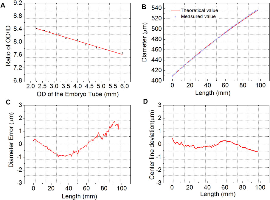
FIGURE 4. Optical measurement results of an MXRL used as a condenser. (A) Ratio of OD/ID versus OD of the embryo tube. (B) Measured (dotted curve) and design ID (solid curve) profile of the MXRL. (C) Diameter error of the MXRL. (D) Center line deviation of the MXRL.
NA is an important parameter of the MXRL used as a condenser in the TXM system. NA match between the condenser and the objective zone plate is a prerequisite for the normal operation of TXM [15]. As for the condenser designed for the laboratory x-ray source, the NA of the ellipsoidal MXRL as a condenser can be easily measured by a series of far-field patterns captured at different distances from the exit of the condenser when the x-ray source was placed at the input focal spot of the ellipsoidal MXRL. However, due to the time limit of the synchrotron radiation, the NA of the condenser hardly directly tests in synchrotron radiation. In this study, we proposed using the microfocusing x-ray tube to measure the NA of the condenser used in synchrotron TXM. The major semiaxis of the MXRL designed as the condenser of synchrotron radiation TXM is usually much longer than the laboratory x-ray optical test platform. In practice, the NA of the condenser was measured with the x-ray source deviated from the input focal spot. As shown in Figure 5, the measured NA (
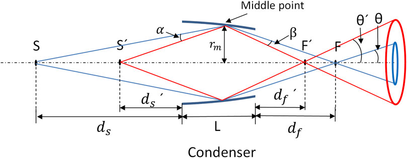
FIGURE 5. Geometric sketch of the x-ray source deviating from the input focal spot of the ellipsoidal MXRL as a condenser for TXM (the blue line represents the transmitting light from the x-ray source to the input focal spot of the condenser, and the red line represents the transmitting light from the x-ray source deviating from the input focal spot).
Therefore, the relationship of the NA of the condenser and the distance
Here,
A tungsten target micro-x-ray tube (L9631, Hamamatsu, Japan) with a focal diameter of 20 μm, operating at 30 kV and 800 μm, was employed in this experiment. An x-ray CCD (C11440-22CU, Hamamatsu, Japan) camera with a 13-μm pixel size was placed downstream of the condenser and was used to acquire the output far-field pattern of the condenser. The condenser was adjusted by a high-precision five-dimensional adjustment platform, which could ensure the lens can be accurately placed in a specific position. The photons from the x-ray tube are reflected from the inner surface of the condenser when the incident angle is smaller than the critical angle of total internal reflection and then are detected by the CCD camera. As shown in Figure 5, the incident angle and the location where the photons are reflected are both determinants of the take-off angle. Thus, the far-field pattern of the condenser was produced. The distance between the MXRL and the micro-x-ray tube is about 80 cm. With the measured method mentioned above, the theoretical NA and the working distance (
The ring shape region of the zone plate in the TXM system is an effective working area used to propagate and magnify the sample image to the CCD detector. In the TXM system, not only the NA of the condenser must match the zone plate but also the illuminating field of the hollow cone beam from the condenser must cover the effective working area of the zone plate. Therefore, the far-field pattern of the condenser is best when a standard ring shape is the effective working area of the condenser. Besides, the intensity distribution of the ring shape facula should be uniform to ensure the uniformity of the image field. The far-field pattern of the condenser mentioned above captured by the CCD detector placed 60 cm away from the condenser is shown in Figure 6. From the figure, we can intuitively observe the roundness and intensity uniformity of the ring shape facula of the condenser.
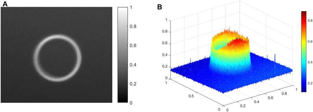
FIGURE 6. (A) Far-field pattern of the condenser. (B) Intensity distribution of the far-field pattern.
To quantitatively describe the suitability of the condenser and the zone plate, a polar coordinate system with the center of the far-field pattern of the condenser as the origin was established as shown in Figure 7. Three sets of data as shown in Figure 8 show the quality of the far-field pattern of the condenser: intensity, proportion of the x-ray photons from the measured condenser irradiating on the theoretical region (the ring with the red line in Figure 7), and the ring width at different angles. The ring shape facula was divided into 12 30° parts . The uniformity of the intensity distribution of the ring shape facula is characterized by its standard deviation. In Figure 8A, the standard deviation of the intensity distribution of the ring shape facula is 0.0387, and the average value of the proportion of the x-ray photons from the measured condenser irradiating on the theoretical region is 91.525%. The standard deviation of “0.0387” indicates the degree to which the far-field pattern of the condenser deviates from the theoretical region, and the proportion of the x-ray photons shows that most photons transmitted from the MXRL can be employed for TXM. Figure 8B shows that the root mean square error of the ring width is 3.1 μm. The intensity distribution with the angle reflects the uniformity of the far-field pattern of the condenser. The higher the proportion of the output x-ray beam irradiating on the theoretical region, the higher the utilization rate of the output x-ray photons from the condenser.
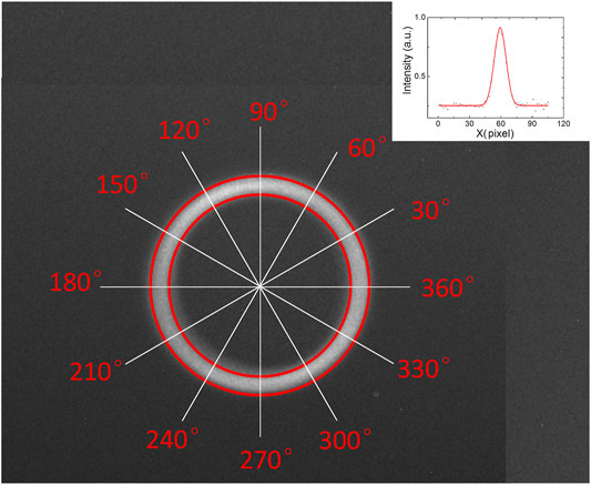
FIGURE 7. Establishment of a polar coordinate system with the center of the far-field pattern of the condenser as the origin (the circle region with the red line is the ideal far-field pattern of the condenser, and the inset at the upper right shows the intensity profile along the white line).
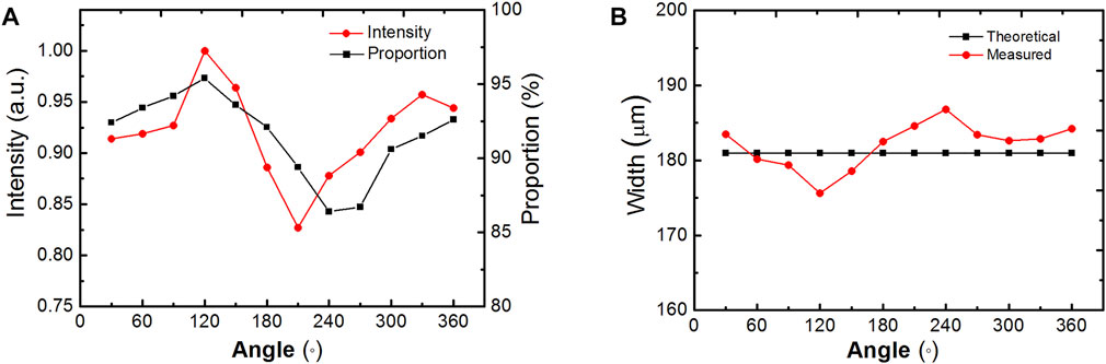
FIGURE 8. (A) Intensity distribution with angle (red line) and proportion of the output x-ray beam irradiating on the theoretical region. (B) Annulus width of the ring shape facula from the condenser at different angles.
The transmission efficiency of the MXRL used as a condenser is a significant parameter that influences the imaging efficiency of the TXM system. It is the ratio of all the reflected x-ray photons to the total incident photons intercepted by the condenser. In our experiment, the transmission efficiency of the condenser was measured by a beam stop and pinhole, as shown in Figure 9. With the assistance of the beam stop and pinhole, the incident x-ray beam can be regulated to only illuminate on the inner surface of the condenser. Using the CCD detector, a reflected and direct facula can be obtained with and without the condenser, respectively. Transmission efficiency can be calculated by dividing the intensity of the reflected and direct facula. The MXRL designed for the SSRF had a transmission efficiency of 81.4%, measured using the laboratory x-ray tube.
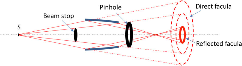
FIGURE 9. Transmission efficiency of the condenser by the beam stop and pinhole.
The performance of the condenser has a significant impact on the performance of the TXM system. The characterization procedure of the MXRL can not only pick out a relatively high-performance MXRL as the condenser in a TXM system but improve the optics manufacturing process according to the feedback of the measurement results. The characterization procedure of the MXRL designed for the condenser in the TXM system includes two parts: optical measurement and x-ray tests. The overall quality of the condenser can be inferred from the optical measurement results of the diameter error and centerline deviation of the condenser. Furthermore, according to the optical measurement results, we can adjust the drawing parameters of the optical fiber drawing machine to make the ID profile of the MXRL be more in line with the ideal one and cut the designed condenser in the proper position from the embryo tube. In the drawing process of the MXRL, the temperature of the heating furnace and the feeding speed of the holder remain unchanged, and the ellipsoidal ID profile of the MXRL is formed by changing the drawing speed. As shown in Figure 10, the ID profile deviates from the ideal one. For the measured ID profile of the MXRL greater and smaller than the design, as shown in Figure 10, we could correspondingly reduce and increase the drawing speed to correct the measured ID profile of the MXRL more close to the ideal profile in the next drawing procession.
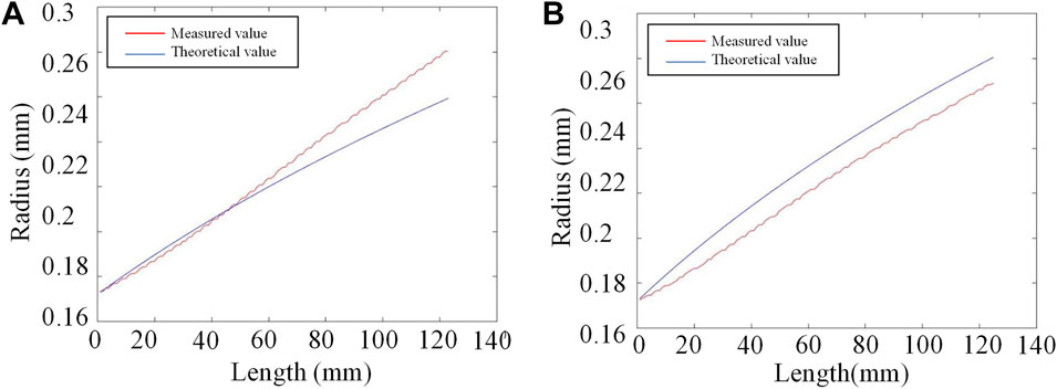
FIGURE 10. ID profile of the embryo tube measured using a light microscope greater (A) and less (B) than the design
The x-ray test with an x-ray source directly indicates the quality of the MXRL as a condenser. Imperfections in the far-field pattern of the condenser are mainly caused by the diameter error and centerline deviation, as mentioned above in the optical measurement. In the past research work, we have simulated that the inner surface imperfections of the condenser influence its performance [23]. The imperfections of the inner surface of the condenser cause nonuniformity in the intensity and ring width of the far-field pattern, which greatly reduces condenser efficiency in the TXM system. Figure 11 shows the simulated and measured deformation of the far-field pattern of the condenser caused by the elliptic deformation and the deviation in the centerline. In the manufacturing process, the main cause of condenser error can be inferred by analyzing the results of optical and x-ray tests. For instance, as shown in Figure 11, for the far-field pattern of the MXRL deformed by elliptic deformation and centerline deviation, we would optimize the manufacturing process by using high-quality glass tubes and rotating the embryo tube to ensure the tube is pulled evenly in the drawing process.
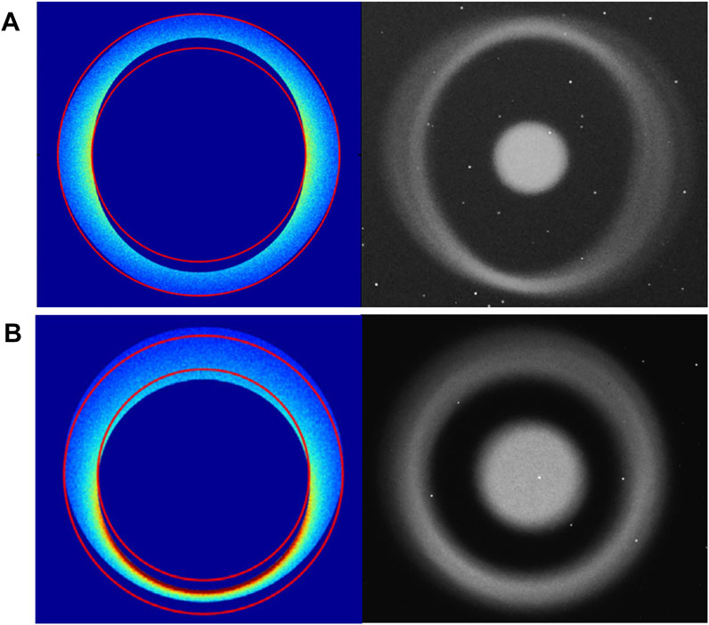
FIGURE 11. Two main kinds of deformation of the condenser resulting in an imperfect far-field pattern. Simulated (left part) and measured (right part) distorted output facula of the condenser caused by elliptic deformation (A) and center line deviation (B) of the condenser (simulated figure cited from Ref. [23]).
In addition, it should be noted that the characterization of the capillary condenser is related to the measuring condition, such as the energy of incident photons and the size of the x-ray source. Compared to monochromic beams from the synchrotron, the polychromic x-ray beams bring about changes in the intensity distribution of the far-field pattern of the condenser while the shape of the image is not affected. In addition, as the x-ray source size increases, the blurred area in the far-field pattern of the condenser and the NA are increasing, which can be calculated by geometrical optics [24].
In this study, the procedure for the characterization of the MXRL as a condenser in the TXM system was presented in detail. The procedure mainly includes optical measurement and x-ray tests. According to the results of the quality assessment procedure, we can not only screen out a high-quality MXRL that meets the design as a condenser of the TXM system but also find out the causes resulting in the mismatch between the condenser and the zone plate and then optimize the condenser manufacturing process. Besides, as for the x-ray test, we established a method that tests the condenser designed for synchrotron TXM using a laboratory x-ray source, which overcomes the limited access of the synchrotron source and accelerates the process of manufacturing high-performance condensers.
The original contributions presented in the study are included in the article/Supplementary Material, further inquiries can be directed to the corresponding author.
TS, XS, and SS developed the methodology, performed the experiments, analyzed the results, and wrote the article. HL, XZ, TY, and FT partially contributed toward implementing the conducted experiments.
This work was supported by the National Natural Science Foundation of China (Grant Nos 11675019 and 12105020) and the Project of Beijing Excellent Talents (2018400685627G334). This work was supported by the Bud project of the Beijing Academy of Science and Technology (BGS202106).
The authors declare that the research was conducted in the absence of any commercial or financial relationships that could be construed as a potential conflict of interest.
All claims expressed in this article are solely those of the authors and do not necessarily represent those of their affiliated organizations or those of the publisher, the editors, and the reviewers. Any product that may be evaluated in this article, or claim that may be made by its manufacturer, is not guaranteed or endorsed by the publisher.
1. Yuan Q, Zhang K, Hong Y, Huang W, Gao K, Wang Z, et al. A 30 Nm-Resolution Hard X-ray Microscope with X-ray Fluorescence Mapping Capability at BSRF. J Synchrotron Radiat (2012) 19:1021–8. doi:10.1107/S0909049512032852
2. Yin G-C, Tang M-T, Song Y-F, Chen F-R, Liang KS, Duewer FW, et al. Energy-tunable Transmission X-ray Microscope for Differential Contrast Imaging with Near 60nm Resolution Tomography. Appl Phys Lett (2006) 88:241115. doi:10.1063/1.2211300
3. Andrews JC, Brennan S, Patty C, Luening K, Pianetta P, Almeida E, et al. A High Resolution, Hard X-ray Bio-Imaging Facility at SSRL. Synchrotron Radiat News (2008) 21:17–26. doi:10.1080/08940880802123043
4. Chu YS, Yi JM, De Carlo F, Shen Q, Lee W-K, Wu HJ, et al. Hard-x-ray Microscopy with Fresnel Zone Plates Reaches 40nm Rayleigh Resolution. Appl Phys Lett (2008) 92:103119. doi:10.1063/1.2857476
5. Tian Y, Li W, Chen J, Liu L, Liu G, Tkachuk A, et al. High Resolution Hard X-ray Microscope on a Second Generation Synchrotron Source. Rev Scientific Instr (2008) 79:103708. doi:10.1063/1.3002484
6. Feser M, Duewer F, Wang S, Scott D, Lyon A, Yun W. 3-D X-ray Microscopy Using a Laboratory Source. Microsc Microanal (2004) 10:1036–7. doi:10.1017/S1431927604880292
7. Tkachuk A, Feser M, Cui H, Duewer F, Chang H, Yun W. High-resolution X-ray Tomography Using Laboratory Sources. In: Developments in X-ray Tomography V, 6318. San Diego: International Society for Optics and Photonics (2006). doi:10.1117/12.682383
8. Tkachuk A, Duewer F, Cui H, Feser M, Wang S, Yun W. X-ray Computed Tomography in Zernike Phase Contrast Mode at 8 keV with 50-nm Resolution Using Cu Rotating Anode X-ray Source. Z Kristallogr (2007) 222:650–5. doi:10.1524/zkri.2007.222.11.650
9. Zschech E, Löffler M, Krüger P, Gluch J, Kutukova K, Zgłobicka I, et al. Laboratory Computed X-Ray Tomography - A Nondestructive Technique for 3D Microstructure Analysis of Materials. Prakt Metallogr (2018) 55:539–55. doi:10.3139/147.110537
10. Andrews JC, Meirer F, Liu Y, Mester Z, Pianetta P. Transmission X-ray Microscopy for Full-Field Nano Imaging of Biomaterials. Microsc Res Tech (2011) 74:671–81. doi:10.1002/jemt.20907
11. Sun Y, Wang Y. Monitoring of Galvanic Replacement Reaction between Silver Nanowires and HAuCl4 by In Situ Transmission X-ray Microscopy. Nano Lett (2011) 11:4386–92. doi:10.1021/nl202538q
12. Chen J, Wu C, Tian J, Li W, Yu S, Tian Y. Three-dimensional Imaging of a Complex Concaved Cuboctahedron Copper Sulfide crystal by X-ray Nanotomography. Appl Phys Lett (2008) 92:233104. doi:10.1063/1.2943337
13. Hsu P-C, Chu Y, Yi J-M, Wang C-L, Wu S-R, Hwu Y, et al. Dynamical Growth Behavior of Copper Clusters during Electrodeposition. Appl Phys Lett (2010) 97:033101. doi:10.1063/1.3464550
14. Nelson GJ, Harris WM, Izzo JR, Grew KN, Chiu WKS, Chu YS, et al. Three-dimensional Mapping of Nickel Oxidation States Using Full Field X-ray Absorption Near Edge Structure Nanotomography. Appl Phys Lett (2011) 98:173109. doi:10.1063/1.3574774
15. Zeng X, Duewer F, Feser M, Huang C, Lyon A, Tkachuk A, et al. Ellipsoidal and Parabolic Glass Capillaries as Condensers for X-ray Microscopes. Appl Opt (2008) 47:2376–81. doi:10.1364/AO.47.002376
16. Stollberg H, Yulin S, Takman PAC, Hertz HM. High-reflectivity Cr∕Sc Multilayer Condenser for Compact Soft X-ray Microscopy. Rev Scientific Instr (2006) 77:123101. doi:10.1063/1.2400665
17. Ge X, Wang ZL, Gao K, Wang DJ, Wu Z, Chen J, et al. Effects of the Condenser Fractal Zone Plate in a Transmission X-ray Microscope. Radiat Phys Chem (2014) 95:424–7. doi:10.1016/j.radphyschem.2013.03.026
18. Rau C, Crecea V, Richter CP, Peterson KM, Jemian PR, Neuhäusler U, et al. Imaging of Micro- and Nano-Structures with Hard X-Rays. Micro Nano Lett (2007) 2:1–5. doi:10.1049/mnl:20065060
19. Jiang B, Liu Z, Sun X, Sun T, Deng B, Li F, et al. Single Bounce Ellipsoidal Glass Monocapillary Condenser for X-ray Nano-Imaging. Opt Commun (2017) 398:91–4. doi:10.1016/j.optcom.2017.04.035
20. Wang Y, Ren Y, Sun T, Tao F, Deng B, Xiao T. Single-bounce Ellipsoidal Capillary for X-ray Microscopes: Design and Measurements. Microsc Microanal (2018) 24:284–7. doi:10.1017/S1431927618013752
21. Zernike F. Phase Contrast, A New Method for the Microscopic Observation of Transparent Objects Part II. Physica (1942) 9:974–86. doi:10.1016/S0031-8914(42)80079-8
22. Huang R, Bilderback DH. Single-bounce Monocapillaries for Focusing Synchrotron Radiation: Modeling, Measurements and Theoretical Limits. J Synchrotron Radiat (2006) 13:74–84. doi:10.1107/S0909049505038562
23. Zhang S, Pan K, Wang Z, Zhou P, Liu Z, Sun X, et al. Simulation of Optical Properties of Ellipsoidal Monocapillary X-ray Optics with Inner-Surface Imperfections. Opt Commun (2021) 493:127028. doi:10.1016/j.optcom.2021.127028
24. Wang Y, Zhang X, Li Y, Sun X, Shao S, Liu Z, et al. Measuring the Average Slope Error of a Single-Bounce Ellipsoidal Glass Monocapillary X-Ray Condenser Based on an X-Ray Source with an Adjustable Source Size. Nucl Instr Methods Phys Res Section A Acc Spectrometers Detectors Associated Eq (2019) 934:36–40. doi:10.1016/j.nima.2019.04.049
Keywords: capillary condenser, zone plate, quality assessment, full-field transmission x-ray microscopy, optical measurement
Citation: Sun X, Shao S, Li H, Zhang X, Yuan T, Tao F and Sun T (2022) A Procedure for the Characterization of Monocapillary X-Ray Lenses as Condensers for Full-Field Transmission X-Ray Microscopes. Front. Phys. 10:821549. doi: 10.3389/fphy.2022.821549
Received: 24 November 2021; Accepted: 08 April 2022;
Published: 04 May 2022.
Edited by:
Qiushi Huang, Tongji University, ChinaReviewed by:
P. S. Athiray, University of Alabama in Huntsville, United StatesCopyright © 2022 Sun, Shao, Li, Zhang, Yuan, Tao and Sun. This is an open-access article distributed under the terms of the Creative Commons Attribution License (CC BY). The use, distribution or reproduction in other forums is permitted, provided the original author(s) and the copyright owner(s) are credited and that the original publication in this journal is cited, in accordance with accepted academic practice. No use, distribution or reproduction is permitted which does not comply with these terms.
*Correspondence: Tianxi Sun, c3R4QGJudS5lZHUuY24=
Disclaimer: All claims expressed in this article are solely those of the authors and do not necessarily represent those of their affiliated organizations, or those of the publisher, the editors and the reviewers. Any product that may be evaluated in this article or claim that may be made by its manufacturer is not guaranteed or endorsed by the publisher.
Research integrity at Frontiers
Learn more about the work of our research integrity team to safeguard the quality of each article we publish.