- 1Anhui Institute of Optics and Fine Mechanics, Hefei Institutes of Physical Science, Chinese Academy of Sciences, Anhui Hefei, China
- 2University of Science and Technology of China, Anhui Hefei, China
- 3Key Laboratory of Optical Calibration and Characterization, Chinese Academy of Sciences, Anhui Hefei, China
- 4Hefei Chief Expert Studio of Agricultural Industry, Anhui Hefei, China
How to effectively eliminate interference such as scattering, absorption, and attenuation is a hot topic of underwater photoelectric detection at present. Around the hot issues, this paper carries out studying the method of polarization-imaging recovery in a dynamic complex underwater environment from the theory of underwater radiation transfer, and numerical simulation of imaging interference characteristics to the simulation of underwater environment experiment. First, by conducting the analysis and simulation of scattering characteristics of underwater suspension particles and bubble by using the theory of radiation transfer, and taking advantage of quantitative description on changing tendency of radiation intensity and polarization properties of light waves in turbid water under the condition of scattering interference. Second, by constructing an underwater target polarization reconstruction model on the basis of the Mueller matrix analysis, and taking target polarization characteristic into reconstruction model on the basis of classical Schechner’s model, automatically estimating polarization information of target by the method of covariance. Finally, by building a polarization imaging system in the simulated complex underwater environment that contains bubble and suspended particles, obtaining reconstructed results with different underwater environments and different materials of target. According to experiment results, and compared with other traditional methods, using the proposed method in this paper can get higher resolution and higher contrast of target in the reconstructed result.
Introduction
Underwater optical imaging plays a very important application value and scientific research significance in the field of marine engineering, including marine biological monitoring, ecosystem assessment, marine rescue, navigation, etc. Compared with atmospheric optical imaging, due to water environment being relatively complex, all kinds of suspension medium in water to light scattering effect will seriously affect the imaging quality, the forward scattering noise can reduce imaging resolution, and the backward scattering noise leads to decrease of imaging contrast [1] The research of underwater imaging technology will focus on taking efforts to reduce influence of optical transmission energy absorption and attenuation on underwater communications and target detection, and prevent the strong scattering effect produced by water. Because target features characterized by polarization information are less affected by water attenuation in the process of underwater transmission, and the polarization characteristics of underwater targets and the surrounding environment have differences, obtaining two orthogonal intensity images in same scenario and using polarization difference imaging method can enhance contrast and resolution of image and weaken the influence of scattering light on target imaging [2]. At present, polarization imaging technology has been widely used in underwater target imaging [2–4] and biomedical imaging [5]. Schechner [6] has proposed a polarization difference reconstruction method where the algorithm has several advantages such as a simple reconstruction model and low computational complexity, providing important reference value on exploration of underwater polarization-imaging. Tali Treibitz [7] has used formulas to take the separation of target information and background information, then polarization information of the target is added into the reconstruction model, he then takes a brief analysis on the forward scattering effect of water body, and the reconstructed results are ideal. Huang [8] has considered target and background light polarization information at the same time in the process of model derivation, and taken correction on three parameters in the model step by step in order to get optimal parameters and achieve the best results of image restoration. Feng [9] has put forward a kind of polarization reconstruction algorithm that estimates degree of polarization (DOP) of global backward scattering light, according to Schechner’s model and definition of DOP, the DOP of reflected light of target have been considered in the model, and have realized clear imaging of underwater target with high DOP. Liu [10] has achieved good results through underwater experiments by using large aperture imaging system for obtaining light-field information with a wide angle and accurately estimating the parameter values that reflect characteristics of a global scene through integration of scene depth information. Tian [11] has combined synthetic aperture imaging with polarimetric imaging and proposed a method for retrieving the radiation of an object based on the degree of polarization and intensity of backward scattering at the multi-view image. AMER [12] has used a polarimetric imaging optical system to reduce the effect of diffusion on the image acquisition and has received a great deal of attention for image dehazing based on an optimized version of the dark channel prior (DCP) method.
Through theoretical analysis and formula derivation, this paper has used expressions to represent reflected light information of target and scattering light information of background respectively, estimated intensity of scattering light and the transmission coefficient, optimized expression of underwater transmission rate, and used a step by step searching method for optimal estimation of polarization information to underwater target, achieved the purpose that the suppressing effect of scattering light on imaging and improved the quality of images. In part 2, this paper takes the mathematical deduction and numerical analysis on backward scattering noise and forward scattering noise and in part 3, describes the basic theory of underwater imaging and the establishment process of a reconstruction model that considers polarization information of underwater target on the analysis of Mueller matrix, and estimates reconstruction parameters. Part 4, builds experiment platform of target polarization-imaging in a complex underwater environment. Part 5, explores the feasibility and validity of the proposed method in this paper by using actively imaging experiments with linear polarized light, which provides theoretical verification for future practical methods of application.
Quantitative Analysis of Scattering Noise Affecting Target Imaging in Underwater Environment
Scattering Noise in Underwater Environment and Classification
In a real environment, water is a very complex mixed medium, which contains water molecules, suspended particles, microorganisms, and its physical properties are related to geography, climate and environment. The inhomogeneity of water lets light waves be affected by absorption and scattering in the transmission, and the attenuation has serious influence on the transmission distance and signal-to-noise ratio. In order to simplify the research situation, the media in the water body can be divided into two kinds of situations: suspended medium and rising air bubble, as shown in Figure 1. Water scattering is the phenomenon of taking migration of motion path of photons due to particle collision, and the scattering effect can make the decrease of strength of the signal at the receiving end, and can cause intersymbol interference. The suspended medium in the water and bubble are often the important factor in the production of scattering phenomenon. These two kinds of influence factors of scattering will be shown in the detailed analysis below.
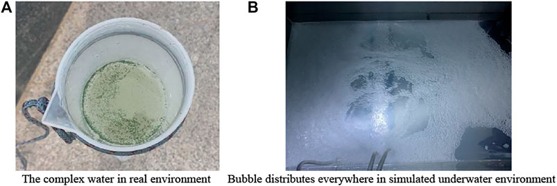
FIGURE 1. Coexistence of suspended medium and rising air bubbles in underwater environment. (A) The complex water in real environment (B) Bubble distributes everywhere in simulated underwater environment.
The Quantitative Simulation Analysis on Scattering Noise Caused by Suspension Medium
In the process of target imaging using active light in an underwater environment, assuming that there exists a small scattering volume element
with
The radiation intensity of the incident light source at site of scattering volume element
The volume scattering function is expressed as
Setting
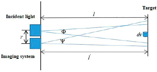
The mathematical analysis and simulation calculation on power of backward scattering
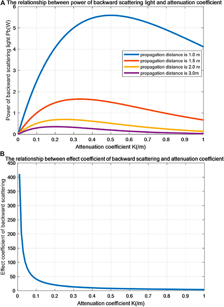
FIGURE 3. The relationship between backward scattering and attenuation coefficient. (A) The relationship between power of forward scattering light and attenuation coefficient. (B) The relationship between effect coefficient of forward scarttering and attenuation coefficient.
In Figure 3A, we can see that power
Defining expression of reflected intensity from underwater target as [11]:
with
Similar to definition of effect coefficient of backward scattering in field of underwater imaging, similarly defining power ratio
Taking mathematical simulation and calculation analysis on power of forward scattering
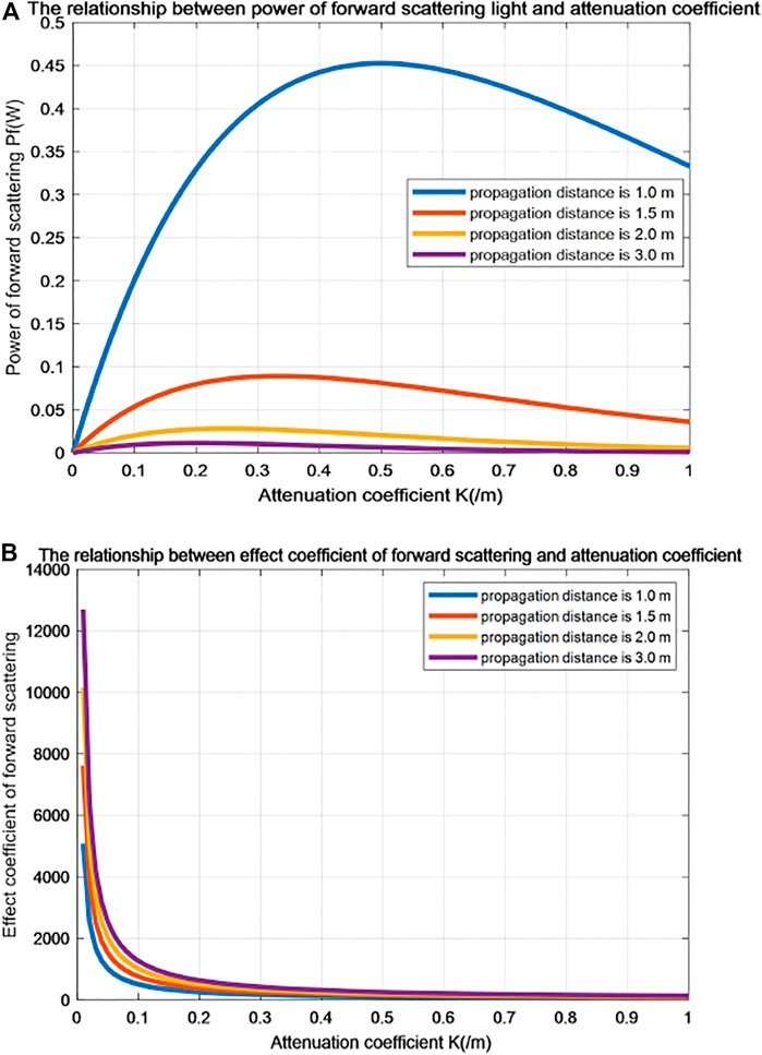
FIGURE 5. The relationship between forward scattering and attenuation coefficient. (A) The relationship between power of forward scattering light and attenuation coefficient. (B) The relationship between effect coefficient of forward scarttering and attenuation coefficient.
Effects of Existence of Bubble on the Target Imaging
Light transmits from a dense medium to a hydrophobic medium of bubbles in water. The incident light in the bubble that runs along the diameter of the bubble remains the same, and the rest of the light completely deviates from the original path and does not reach the detector. As the surface area of the bubble increases, increasingly more light is refracted, the light that reaches the probe decreases, and the light intensity detected decreases. Because diffraction is more complex, this paper simplifies light transmission formation in the bubble geometrical optics. Fresnel law indicates that the reflectivity and transmissivity are connected with the polarization and incident angle of incident light and the refractive index of the medium. Any polarization of light can be decomposed into a pair of mutually perpendicular components, a vibrating direction perpendicular to the plane of incidence, expressed as S, and another vibrating direction parallel to the plane of incidence, expressed as P. According to [17] the Fresnel formula, we can obtain the reflection coefficient and the refraction coefficient expression of the polarized component expressed by P . Similarly, we can obtain the reflection coefficient and refraction coefficient expression of the polarized component expressed by S. The theoretical calculation shows that the light intensity on the bubble interface decreases continuously with increasing transmission time, and for the fourth reflection and refraction cycle, the intensity of refracted light of bubble tends to zero [16]. The value of DOP increases with increasing transmission frequency, and at the interface in the fourth transmission cycle, DOP of refraction and reflection light is the largest, being converted to almost completely polarized light [17].
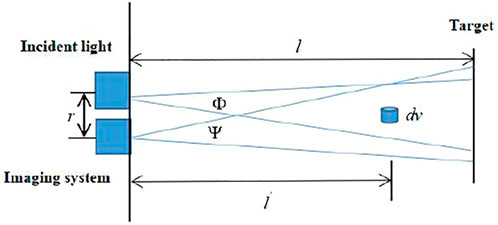
Regarding the influence of distance between bubble group and imaging system on acquisition of underwater image, the related schematic diagram is shown in Figure 6A. Setting same integration time when distance is long, bubble are alike to suspended particles and cover target information. When distance is shorter, bubbles are equivalent to a layer of lens and the amount of light does not decline, but increase [16]. Form and expression of bubble in image are different when the camera is set in different integration time. When integration time is small, bubbles are alike to a white dot in an image, the intensity value has no relation to intensity of background and is only related with its bubble brightness. When integration time is bigger, bubbles are alike to a blocking strip, and affect brightness of the target area, and its intensity and intensity of the background has a certain linear relationship [16], the related schematic diagram is shown in Figure 6B.
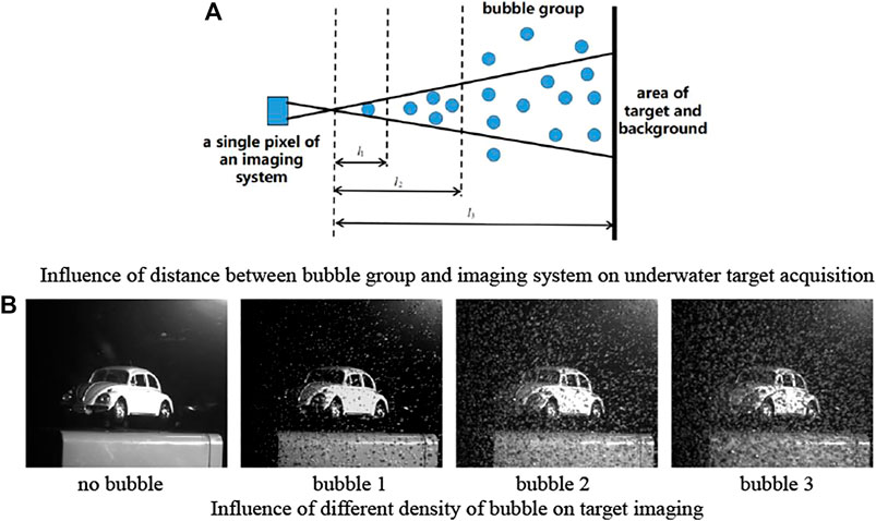
FIGURE 6. Exploration of influence of bubble group on underwater target acquisition. (A) Influence of distance between bubble group and imaging system on underwater target acquisition (B) Influence of different density of bubble on target imaging.
The relative difference of the polarization information of the target and background region will be different with the change of incident angle of light source under the condition of bubbles. Under the condition of the same bubble thickness, target polarization information of different material are different. When the thickness of the bubble is higher, intensity and polarization imaging techniques are difficult to identify the underwater target, as can be seen in Figure 6B. According to the scattering theory, the suspending medium and bubble will produce certain polarization characteristics in the process of light transmission, it also does some bedding for the subsequent content of target polarization imaging.
Establishment of Polarization Reconstruction Model of Underwater Target and Parameter Estimation
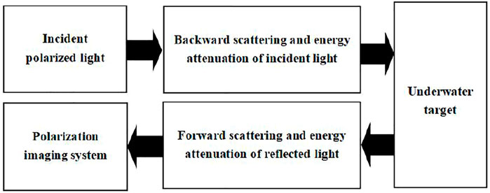
As shown in Figure 7, from the microscopic perspective in underwater target imaging, incident light takes transmission into the surface of the target, and energy redistribution and reflection occurs on the surface of the target, then reflected light of the target enters into CCD detector of the imaging system with attenuation, because reflected light of this road carrying information of target and are different with other locations of stray light and polarization information, therefore we can make use of the method of polarization imaging to suppress stray light, highlight information of target, so as to realize clear imaging of target under complex underwater environment.
Underwater Polarization Imaging Measurement Theory
The polarization expression of incident light is
The Mueller matrix can fully describe the relationship of the change of polarization with wavelength, scattering angle, scattering particle size, shape and concentration and other parameters in the single scattering. The diagram of underwater target polarization detection is shown in Figure 8A, where Pol1 represents the polarization generator, Si represents Stokes vector i.
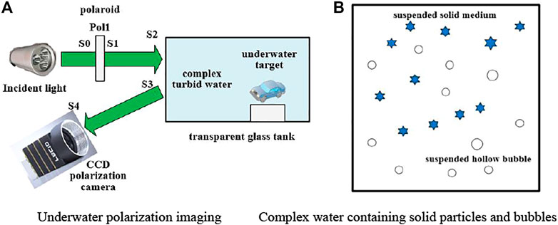
FIGURE 8. The schematic diagram of underwater polarization imaging. (A) Underwater polarization imaging. (B) Complex water containing solid particles and bubbles.
The linear combination of three kinds of light and construction of underwater light transmission model are shown in as:
with
When incident light has passed through the partial device Polar1, the Mueller matrix is defined as
The process of transmission of incident light to the target, the Mueller matrix of water is defined as
Supposing the Mueller matrix of the target is
In the process of reflection and transmission of light source from the target surface to the CCD imaging system, setting the Mueller matrix of water is
Arrived at the CCD imaging system, the definition of Mueller matrix of partial detector Polar2 in CCD imaging system is
According to Figure 8, the underwater target polarization imaging using the Mueller matrix to take concrete analysis on the light transmission process steps are as follows: Step 1) setting the incident light is natural light, and setting its polarization is
Step 3) the aquatic environment shows different physical properties with the change of attenuation coefficient, the Mueller matrix expression of water is as follows:
When medium is uniform distribution in water and only the Rayleigh scattering occurs, in order to simplify the analysis process, the Mueller matrix expression will be changed to [1]:
with
Due to suspension medium in water belongs to the dynamic change, different concentration of suspension medium will show different polarization characteristics, and also can have different Mueller matrix, and its expression is more complicated. It can make use of the Monte Carlo method to simulate its polarization characteristics under the condition of different medium concentration of water (different attenuation coefficient). In order to analyze the relationship of underwater radiation transmission characteristics of polarized light with wavelength of incident light and thickness of scattering medium, this paper uses Monte Carlo method to simulate the change trend of intensity and DOP of backward scattering, and related parameter settings in simulation process are as follows: wavelength of incident light are set to 450, 550, 650 nm, respectively. Radius of suspended particle in water is 2 microns, medium layer are same kind of suspended particles, refraction coefficient of particle is set to 1.15, weight threshold is 0. When incident light is horizontal linear polarized light, taking calculation on average value of intensity and DOP of received photon, thus the corresponding mean curve of scattering intensity and DOP with change of thickness to scattering medium are shown in Figure 9, the longitudinal axis represents average value of intensity and DOP to all photons received by receiving surface, and the horizontal axis represents thickness coefficient of scattering medium.
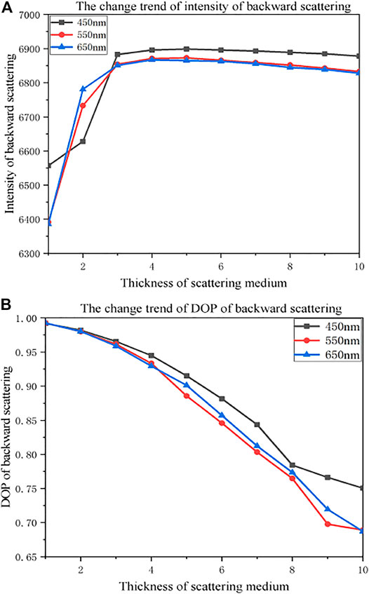
FIGURE 9. The change trend of intensity and DOP of backward scattering light in underwater environment. (A) The changes trend of intensity of backward scattering. (B) The change trend of Dop of backward scattering.
Due to scattering phenomenon of suspended particles in water, polarized light will become partly polarized light, appearing as the phenomenon of depolarization, with increasing of medium thickness (transmission distance), and incident light taking transmission among particles, the probability of photons absorbed and the number of scattering are constantly improving, leading to variation of original polarization state to polarized light, and becoming another kind of state of polarized light, with the degree of depolarization shows monotone decreasing. When medium thickness is greater, the medium layer is equivalent to a reflection plane [19], so scattering intensity shows a rapid increasing trend firstly, and then decreasing slowly. As for incident light source with different wavelengths appearing at different attenuation degrees when transmitting in water, intensity and polarization information of backward scattering also shows different values with the change of transmission distance. Step 4) is the polarization characteristics of the target, and its Mueller matrix expression can be defined as follows:
The photoelectric field vector of incident light, reflected light, and refracted light can be decomposed into the component P parallel to the incident plane and the component S perpendicular to the incident surface, based on the Fresnel’s law, reflectance and transmittance of amplitude are
with
Underwater Polarization Imaging Reconstruction Method of Removing Scattering
The directly transmitted light of underwater target
with
After Mueller matrix calculation of target area in turbid environment, the Stokes vector expression of target is obtained by CCD imaging system as follows:
Supposing internal partial detector of polarization CCD imaging system is Polar2, when the partial detector Polar1 and the partial detector Polar2 are parallel, ideally
The backward scattering light
with
In water environment, using Mueller matrix to calculate the area of backward scattering light, CCD imaging system can get the Stokes vector expression of backward scattering light which is:
when the partial detector Polar1and the partial detector Polar2 are parallel, ideally
We use the focal plane polarization camera to take data acquisition, the camera can obtain four intensity images at different polarization direction at one-time, I0, I45, I90, I135 respectively, and can obtain Stokes vector of target reflection and backward scattering light after passing through water at the same time. This paper uses method of curve fitting to obtain the best image of orthogonal polarization, taking Stokes vector and fitting out the curve of relationship between
In an underwater environment, because the forward scattering mechanism are more complicated, the influence extent of backward scattering is greater than the forward scattering this article does not take the forward scattering factor into subsequent process of modeling, and specific content can refer to Section 2. According to Equation (3-2), the maximum intensity expression and minimum intensity expression are shown in Equation (3-20):
Using Equation (3-20) can get intensity expression of underwater scene as shown in Equation (3-21):
According to calculation formula of DOP, the DOP of underwater scene light
Uniting Equation (3-20) to Equation (3-22) can obtain expressions on synthesis intensity and differential intensity of underwater scene light expressed as follows:
Equation (3-24) can be derived by Equation (3-23):
Using Equation (3-24) can further conclude new rate transmission expression
Uniting Equation (3-22) to Equation (3-24) can obtain intensity information of underwater target
As you can see, in the polarization reconstruction model of underwater target of Equation (3-26), we have considered the reflected radiation of underwater target containing polarization information. Compared with traditional underwater light transmission map [4], the new expression of transmission rate
with the effective intensity information of reflected target light is defined as
The degree of polarization of backward scattering light is automatically estimated for the non-target region, as shown in the following equation:
with
with
with
As can be seen from the above estimation process of polarization parameter, estimation of underwater target polarization information
The covariance can be expressed as:
Covariance is function expression of DOP to target
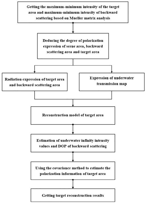
The structure of underwater polarization imaging reconstruction algorithm is shown in Figure 10.
Complex Underwater Environment Polarization Imaging Experiment and Quantitative Analysis of Result
Setting up Polarization Imaging Experiments in Dynamic Complex Underwater Environment
In order to verify the validity of the polarization reconstruction method, we have carried out polarization imaging experiments of an underwater target. A transparent glass tank was used in the underwater imaging experiment, according to the principle of actively optical underwater transmission in Section 2 and requirements in actual scene, using an LED lamp with high power that has been installed one polaroid in front of experiment for lighting target, it is shown in Figure 8A. Emission light first passed through line-polaroid and is transformed into polarized light and arrives to targets, then reflected light from the target surface enters into the imaging system, where the imaging system will collect polarization images that are taken into the terminal equipment for eventual data processing. Relevant data show that the average concentration of suspended medium is 0.8–2.5 mg/L in seawater, and milk can simulate the scattering characteristics of seawater [22]. The relative refractive index of tap-water at room temperature is 1.333, volume attenuation coefficient is about 0.15 m−1. Real underwater experiment scene is shown in Figure 11A and Figure 11B. A LUCID focal plane polarization camera was used in the experiment, as shown in Figure 11C. The polarization filter is added to the front location of pixel in this camera, each 2*2 pixel array have four different directions of polarization filter (0°, 45°, 90° and 135°), and the camera takes output intensity and polarization information of each image pixel [23]. Specific parameters of the LUCID polarization camera are referred to in Table 1. According to the experiment scene, camera exposure time is set in 5,000 microseconds and kept unchanged. The calculation formula of Stokes vector are shown in Equation (4-1):

FIGURE 11. Diagram of dynamic turbid underwater complex environment and experimental scene. (A) Intensity map with bubble (B) Intensity map with bubble and suspended medium (C) LUCID camera.
In the experiment, using the process of dropping milk into a transparent glass tank containing water, step by step, for quantitatively controlling the quality of water in order to simulate suspended particles in water, and installing bubble generator in the front of target to simulate real environment of underwater exploration, the experiment scene of complex underwater environment is shown in Figure 11. In the experiment, bubble density is defined as bubble 1, bubble 2 and bubble 3, respectively, with different numbers of bubble generators: one bubble generator represents bubble 1, two bubble generators represent bubble 2, three bubble generators represent bubble 3, and suspended medium density are defined as density 1, density 2 and density 3, respectively, with different concentrations of milk Adding 1 ml of milk represents density 1, adding 2 ml of milk represents density 2, adding 3 ml of milk represents density 3. Target area contains a small-sized gun.
The Result of Experiment and Analysis of Processed Images
Experimental data collection are divided into three kinds of circumstances. The first kind of circumstance is to explore image recovery results under the condition of different bubble density, without adding milk into the water. The second is to explore image recovery results under the condition of different concentrations of suspended medium, without adding bubble into the water. The third is to explore image recovery results under the condition of the coexistence of suspended medium with bubble (bubble density belongs to high density, named bubble 3, and concentration of suspended medium is different).
1) Exploring the influence of different bubble density on target imaging
In this experimental scenario, a small-sized gun is placed in a dynamic underwater complex environment. Collecting original images in all-pass channel under four different polarization directions by polarization-imaging system, synthetic original intensity images under the condition of different bubble density are shown respectively, in Figure 12A. It can be seen that the existence of bubble has affected the common optical imaging of target to a certain extent, intensity value decreases with the increase of bubble density. The degree of polarization under the condition of different bubble density are shown, respectively, in Figure 12B. After calculation, with the increase of bubble density and the degree of polarization of target region and background region gradually decrease, but compared with ordinary optical imaging, the polarization imaging has obvious advantages such as suppressing noise interference on imaging. Figure 12C are reconstructed images proposed by this paper, and compared with original intensity figures, reconstructed images overall have better quality and better vision.
2) Exploring the influence of different media concentration on target imaging
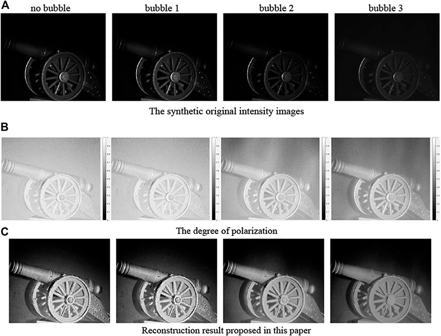
FIGURE 12. Effects of different density of bubble on target polarization imaging. (A) The synthetic original intensity images. (B) The degree of polarization. (C) Reconstruction result proposed in this paper.
The second case is shown in Figure 13. The proposed method in this paper has proved that clear imaging method of underwater target can effectively suppress backward scattering that reduces contrast of image, and the proposed method still has a certain effectiveness when concentration of suspended medium is high.
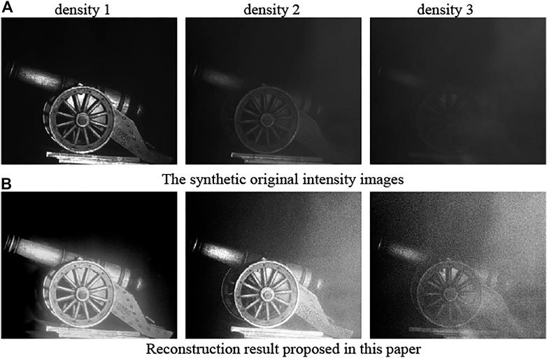
FIGURE 13. Figure processing under the condition of different density of medium without bubble. (A) The synthetic original intensity images. (B) Reconstruction result proposed in this paper.
3) Coexistence of bubble and suspending medium
The third case will explore the influence of different media concentration on target imaging in condition of bubble concentration is bubble 3, as shown in Figure 14. The proposed method in this paper has also proved that clear imaging method of underwater target can effectively suppress backward scattering and noise that reducing clearity of image, the proposed method have a certain effectiveness under the condition of a dynamic complex underwater environment.
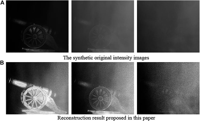
FIGURE 14. Figure processing under the condition of different density of medium with bubble density is bubble 3. (A) The synthetic original intensity images. (B) Reconstruction result proposed in this paper.
According to results in Figure 12, Figure 13 and Figure 14, it can be concluded that the reconstruction method proposed in this paper can get clear recovery results of underwater target when waveband is all-pass [24]. In order to prove the applicability of the algorithm, we took polarization imaging experiments of four target groups made of different material under the conditions of all-pass waveband in complex underwater environment. Figure 15A shows synthetic original intensity images, Figure 15B shows the processed results of Schechner’s method, Figure 15C shows the processed results of Tali’s method, Figure 15D shows the processed results of proposed method in this paper. It also can be seen that the proposed method can restrain effects of underwater particle scattering and bubbles on the imaging of the target, and the recovery images have greatly been improved in resolution and texture detail, and processed detail edge is better.
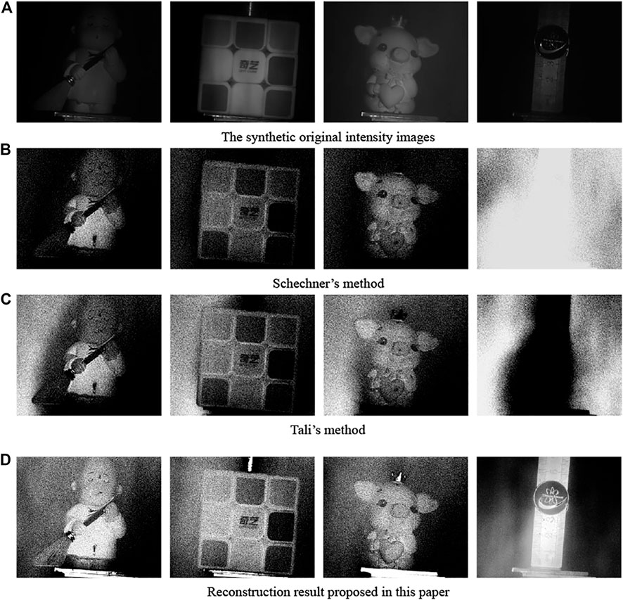
FIGURE 15. The processing results of other material target under the condition of bubble concentration is bubble 3 and medium concentration is density 1. (A) The synthetic original intensity images. (B) Schechner’s method. (C) Tali’s method. (D) Reconstruction result proposed in this paper.
Comparative Analysis of Classic Methods
Existing underwater polarization recovery method generally has the following challenges: 1) Obtaining orthogonal polarization images by using method of artificially spinning polarization analyzer or ways of directly taking operation on camera device that have not been calibrated, the selection of the best and worst polarization direction will affect recovery result are good or bad. 2) When constructing a polarization reconstruction model of an underwater target by directly borrowing formula of atmospheric scattering model, there will be a certain treatment effect, but the underwater environment and the atmospheric environment have some differences, such as types of media and the degree of light attenuation, so there is a need for further optimization of the polarization reconstruction model. 3) The manual way to estimate parameters and processed time of algorithm is long, so these proposed methods are difficult to meet the demand of practical applications on underwater target imaging. It is found in experimental process that Schechner’s method [6] and Tali’s method [7] use artificial selection of background region to estimate parameters and substitute constant value to calibrate polarization reconstruction parameters, these method increases the complexity of the recovery algorithm, and can’t solve disadvantages of recovery effect are not well that only estimating parameters in one background area. Using the way of actively calculating polarization parameters to get reconstructed parameters and using the way of bright color principle to automatically estimate optimal intensity values of underwater infinite background, can reasonably solve the above problems in this article. When using the maximum and minimum intensity algorithm to calculate the intensity the polaroid does not need to be manually turned. The target polarization information in the model was taken into account and the covariance method to automatically estimate the parameters of underwater target polarization information was used. Compared to the original intensity image and recovery results of other methods, processed results by using the proposed method can enhance the definition of results, and targets can be well distinguished.
Conclusion
This paper has carried out imaging studies of targets in an underwater environment from theoretical derivation, numerical simulation of environmental noise, underwater polarization-imaging experiments, and restored processing of images. Taking theoretical derivation and simulation on noise analysis of backward scattering field and forward scattering field in underwater environment, it is concluded that power of backward scattering light and forward scattering light show a change trend of firstly increasing and then decreasing with increasing of attenuation coefficient, effect coefficient of backward scattering and forward scattering decreases with increasing of attenuation coefficient, power of backward scattering light is greater than power of forward scattering light, the degree of influence of backward scattering is greater than forward scattering in underwater imaging. Polarization information of the target has been considered in the polarization imaging model of underwater target, and the way of estimating the underwater transmission rate has improved, obtaining good recovery effect through adaptive estimation method of optimal polarization information parameters. Designing polarization imaging experiments of underwater targets with different concentrations of suspension medium and bubble and different materials under complex environment. The coexistence of the suspension medium and bubble in the complex water at the same time, and combine Section 2 to the scattering noise analysis, explores the result of the underwater target polarization imaging and recovery under different materials and water environment. According to experiments of underwater polarization-imaging and contrast results of processed images, we can see that targets restored by the proposed method have high resolution, and verify the validity of proposed method. Finding the best observation condition in a complex underwater environment for clear target imaging will be our research priorities in the future.
Data Availability Statement
The raw data supporting the conclusions of this article will be made available by the authors, without undue reservation.
Author Contributions
All authors listed have made a substantial, direct and intellectual contribution to the work, and approved it for publication.
Funding
We received financial support by the National Key R&D Program of China (Grant No. 2016YFE0201400) and the Key Project of Hefei Research Institute of Chinese Academy of Sciences (Grant No. Y73H9P1801).
Conflict of Interest
The authors declare that the research was conducted in the absence of any commercial or financial relationships that could be construed as a potential conflict of interest.
Publisher’s Note
All claims expressed in this article are solely those of the authors and do not necessarily represent those of their affiliated organizations, or those of the publisher, the editors, and the reviewers. Any product that may be evaluated in this article, or claim that may be made by its manufacturer, is not guaranteed or endorsed by the publisher.
References
1. Amer KO, Elbouz M, Alfalou A, Brosseau C, Hajjami J. Enhancing Underwater Optical Imaging by Using a Low-Pass Polarization Filter. Opt Express (2019) 27:621–43. doi:10.1364/OE.27.000621
2. Han P, Liu F, Wei Y, Shao X. Optical Correlation Assists to Enhance Underwater Polarization Imaging Performance. Opt Lasers Eng (2020) 134:106256. doi:10.1016/j.optlaseng.2020.106256
3. Li X, Hu H, Zhao L, Wang H, Yu Y, Wu L, et al. Polarimetric Image Recovery Method Combining Histogram Stretching for Underwater Imaging. Sci Rep (2018) 8:12430. doi:10.1038/s41598-018-30566-8
4. Fade J, Panigrahi S, Carré A, Frein L, Hamel C, Bretenaker F, et al. Long-range Polarimetric Imaging through Fog. Appl Opt (2014) 53:3854–65. doi:10.1364/AO.53.003854
5. Pierangelo A, Manhas S, Benali A, Fallet C, Totobenazara J-L, Antonelli M-R, et al. Multispectral Mueller Polarimetric Imaging Detecting Residual Cancer and Cancer Regression after Neoadjuvant Treatment for Colorectal Carcinomas. J Biomed Opt (2013) 18:046014. doi:10.1117/1.jbo.18.4.046014
6. Schechner YY, Karpel N. Recovery of Underwater Visibility and Structure by Polarization Analysis. IEEE J Oceanic Eng (2005) 30:570–87. doi:10.1109/JOE.2005.850871
7. Treibitz T, Schechner YY. Active Polarization Descattering. IEEE Trans Pattern Anal Mach Intell (2009) 31:385–99. doi:10.1109/TPAMI.2008.85
8. Huang B, Liu T, Hu H, Han J, Yu M. Underwater Image Recovery Considering Polarization Effects of Objects. Opt Express (2016) 24:9826–38. doi:10.1364/OE.24.009826
9. Feng F, Wu GJ, Wu YF, Miao YH, Liu B. Algorithm for Underwater Polarization Imaging Based on Global Estimation. Acta Opt. Sin. (2020) 40:2111002. doi:10.3788/AOS202040.2111002
10. Liu B, Zhao P-X, Zhao X, Luo Y, Zhang L-C. Multiple Aperture Underwater Imaging Algorithm Based on Polarization Information Fusion. Acta Phys Sin (2020) 69:184202. doi:10.7498/aps.69.20200471
11. Tian Y, Liu B, Su X, Wang L, Li K. Underwater Imaging Based on LF and Polarization. IEEE Photon J. (2019) 11:1–9. doi:10.1109/JPHOT.2018.2890286
12. Wei Y, Han P, Liu F, Shao X. Enhancement of Underwater Vision by Fully Exploiting the Polarization Information from Stokes Vector. Opt Express (2021) 29:22275–87. doi:10.1364/OE.433072
13. Qian WX, Bai LF, Chen Q, Gu GH. Theoretical Study on Back-Scattering Model of Laser's Transmission Underwater Based on Frequency Domain. Infrared Laser Eng (2006) 35:441–4. doi:10.3969/j.issn.1007-2276.2006.04.015
14. Ge WL, Hua LH, Zhang XH, Han HW. Calculation of Water Backscattering Light Energy Distribution in Range-Gated Underwater Laser Imaging System. J Naval Univ Eng (2013) 25:53–6. doi:10.7495/j.issn.1009-3486.2013.02.010
15. Zhong SC, Li ZR, Wang RB. Forward-scattering Effect on Underwater Laser Imaging. High Power Laser and Particle Beams (2012) 24:61–4. doi:10.3788/HPLPB20122401.0061
16. Tang YH, Xie GY, Liu HC, Shao JB, Ma Q, Liu HP, et al. Study of the Interface Optical Property of Bubbles in Water Based on PIV. Acta Phys Sin (2006) 55:2257–62. doi:10.7498/aps.55.2257
17. Liang SY, Wang JA, Zong SG, Wu RH, Ma ZG, Wang XY, et al. Laser Detection Method of Ship Wake Bubbles Based on Multiple Scattering Intensity and Polarization Characteristics. Acta Phys Sin (2013) 62:62060704. doi:10.7498/aps.62.060704
18. Garg K, Nayar SK. Vision and Rain. Int J Comput Vis (2007) 75:3–27. doi:10.1007/s11263-006-0028-6
19. Cariou J, Le Jeune B, Lotrian J, Guern Y. Polarization Effects of Seawater and Underwater Targets. Appl Opt (1990) 29:1689. doi:10.1364/AO.29.001689
20. Cao Nian-Wen NW, Liu Wen-Qing WQ, Zhang Yu-Jun YJ. Measuring the Depolarization for Scattering Light at Several Kinds of Media. Acta Phys Sin (2000) 49:647–53. doi:10.7498/aps.49.647
21. Rahman Z, Yi-Fei P, Aamir M, Wali S, Guan Y. Efficient Image Enhancement Model for Correcting Uneven Illumination Images. IEEE Access (2020) 8:109038–53. doi:10.1109/access.2020.3001206
22. Agaian SS, Panetta K, Grigoryan AM. Transform-based Image Enhancement Algorithms with Performance Measure. IEEE Trans Image Process (2001) 10:367–82. doi:10.1109/83.908502
23. Li HY, Li CY, Li XB, Wang H, Hu HF, Liu TG. Optimization of Polarization-Camera-Based Full Stokes Polarimeter. Acta Opt. Sin. (2020) 40(3):0326001. doi:10.3788/AOS202040.0326001
Keywords: underwater transmission rate, polarization filtering, target polarization information, image reconstruction, imaging waveband
Citation: Song Q, Liu X, Huang H, Ti R and Sun X (2022) Polarization Reconstruction Algorithm of Target Based on the Analysis of Noise in Complex Underwater Environment. Front. Phys. 10:813634. doi: 10.3389/fphy.2022.813634
Received: 12 November 2021; Accepted: 25 January 2022;
Published: 31 March 2022.
Edited by:
Haofeng Hu, Tianjin University, ChinaCopyright © 2022 Song, Liu, Huang, Ti and Sun. This is an open-access article distributed under the terms of the Creative Commons Attribution License (CC BY). The use, distribution or reproduction in other forums is permitted, provided the original author(s) and the copyright owner(s) are credited and that the original publication in this journal is cited, in accordance with accepted academic practice. No use, distribution or reproduction is permitted which does not comply with these terms.
*Correspondence: Xiaobing Sun, eGJzdW5AYWlvZm0uYWMuY24=
 Qiang Song
 Xiao Liu1,3,4