- Photoacoustics and Ultrasound Laboratory Eindhoven (PULS/e), Department of Biomedical Engineering, Eindhoven University of Technology, Eindhoven, Netherlands
The heart is a complex organ with a high level of deformation occurring in different directions. Ultrasound imaging has proven to be a valuable tool to quantify these deformations. However, strain is not always measured accurately in vital parts of the heart when only using a single probe, even at a high frame rate, because of the anisotropic spatial resolution and contrast. Therefore, a multi-perspective ultrafast ultrasound (US) strain imaging method was developed, aiming at investigating improvements in strain while operating two probes at different relative angles. In an ex-vivo experiment of a beating porcine heart, parasternal short axis views of the left ventricle (LV) were acquired by two phased array probes with different relative angles (30°–75°) at a frame rate of 170 frames per second (FPS). A fully automatic registration algorithm was developed to register the image datasets for all cases. Next, radio frequency (RF) based strain imaging was performed. Axial displacements were compounded based on the unit axial vectors of the dual probes to improve motion tracking and strain estimation. After performing multi-perspective strain imaging, compounded radial and circumferential strain both improve compared to single probe strain imaging. While increasing the inter-probe angle from 30° to 75°, the mean tracking error (ME), mean drift error (MDE) and strain variability (SV) decreased, and signal-to-noise ratio (SNRe) increased for both strain components. For the largest angle (75°), large reductions in ME (−42%), MDE (−50%) and SV (−48%) were observed. The SNRe increased by 253 and 39% for radial and circumferential strain, respectively, and strain curves revealed less noise for each region. In summary, a multi-perspective ultrafast US strain imaging method was introduced to improve cardiac strain estimation in an ex-vivo beating porcine heart setup.
Introduction
Speckle tracking echocardiography (STE) has emerged as a quantitative and comprehensive method to accurately estimate LV myocardial function and contractility [1, 2]. STE allows the measurement of myocardial deformation by tracking speckles on B-mode or RF data, in 2-D and 3-D, in the long-axis, short-axis, and apical views of the hearts [3]. Numerous studies have shown that STE can provide valuable information for early detection of local LV dysfunction and thus significant insights into the pathophysiology of ischemic heart disease [4–6]. STE algorithms generally use a block-matching approach to track the speckles in a sequence of B-mode or RF image data [7]. STE is superior to Tissue Doppler imaging, particularly regarding noise and angle dependency [8]. Moreover, STE provides information on strain in more than one direction. By tracking each speckle in the region of interest during one cardiac cycle frame to frame, strain in different directions can be estimated. However, the accuracy of speckle tracking is dependent on image quality and frame rate, and performs considerably worse in the non-axial directions.
Currently, the optimal frame rate of speckle tracking is between 50 and 80 FPS for clinical applicability to measure myocardial strain [9]. However, to obtain such a frame rate using conventional US machines, image resolution and scan-line density are inevitably reduced. High image quality is beneficial to measure strain accurately, but at the cost of low temporal resolution, resulting in under-sampling, decorrelation, and anisotropic speckle patterns in the images. In some cases, such as the evaluation of coronary artery disease and stress echoes (where the heart rate increases), a higher frame rate over 80 FPS is required [10]. For this reason, using conventional US imaging machines to acquire the entire LV myocardium and quantify the LV myocardial deformation locally at such a high frame rate is not feasible.
Recently, ultrafast US imaging is playing an important role in new advances in echocardiography since its high frame rates enable capturing rapid cardiac motion, leading to an abundance in novel diagnostic or prognostic information [11–13]. Both focused and unfocused US transmission technologies have been developed. Multi-line acquisition (MLA) reduces the number of scan lines and transmits beams with a wide opening angle together with parallel receive beamforming. As a result the frame rate can be increased [14]. Multi-line transmit (MLT) is an alternative that applies receive beamforming in parallel and transmits multiple focused beams into different directions simultaneously. The frame rate can be improved accordingly [15]. Moreover, MLT can easily be combined with MLA techniques to gain an 8-fold increase in frame rate. However, the main disadvantage of these technologies is the degradation of lateral resolution and artifacts [16]. Plane wave or diverging wave imaging methods have also been proposed to achieve a high frame rate using the full aperture of the transducer [17]. Unfocused acquisition schemes allow more lines to be reconstructed in parallel while keeping good energy penetration. However, the spatial resolution decreases vastly due to the width of the broad beam increasing with depth. As a solution, coherent spatial compounding of steered spherical waves was introduced to improve spatial resolution and SNR [18]. However, coherent spatial compounding is only beneficial in a limited, overlapping region-of-interest in deeper lying structures. In cardiac imaging, limited by the anatomy of the ribs, using a phased array probe only allows for steering with small angles due to its intrinsic small footprint.
Therefore, using a single probe to perform STE and measure cardiac strain is limited, even at a high frame rate, due to the limited resolution in certain areas of the heart. Because of the complexity and dynamicity of the heart, inhomogeneous and high-level strain occur in all directions. When the strain direction is parallel to the direction of the US beam (axial direction), it can be measured accurately, benefiting from the good contrast and resolution in this direction. However, suffering from the low image contrast and poor resolution in the lateral direction, it is difficult to measure lateral strain precisely.
Multi-view and multi-probe imaging have been introduced for cardiac applications, showing promising results in improving lateral resolution and contrast [19–24]. However, its major shortcoming is the use of separate US image acquisitions, obtained manually at different time points, which can result in misalignment of the images due to changes in hemodynamic variables such as heart rate or ventricular pressure. Moreover, compounding the strain data acquired from different time points using multi-view imaging is non-trivial and will unavoidably lead to inaccuracies, given the rapid motion and contraction of the heart, as well as possible variability in heart rate from cycle to cycle.
Hence, a different approach based on multi-perspective US imaging that can perform ultrafast interleaved imaging and compound strain data has the potential to greatly improve performance. The major advantage is, that the US data acquired by the two probes are highly correlated, which makes image registration and strain compounding feasible. In addition, no separate recording and temporal registration are needed. Improvements of this method in image quality and vascular strain imaging have been demonstrated in a mock circulation setup using a porcine aorta [25–27]. However, for cardiac imaging, considering the limited imaging windows, asymmetrical and inhomogeneous deformation pattern, and high strain levels in different regions of LV, a different imaging setup and strain compounding method are required. Furthermore, this approach for cardiac imaging needs to be based on phased array probes and requires testing and validation under realistic conditions, before translation into the clinic.
This study introduces a multi-perspective ultrafast cardiac strain imaging method to improve 2-D cardiac strain measurements. The advantages and performance of multi-perspective STE will be demonstrated experimentally using a sophisticated beating porcine heart setup [28], and evaluated for different relative probe positioning, i.e., increasing relative angle between the two probes. Moreover, a novel compounding method for interleaved multi-perspective US based strain imaging is introduced (unit axial vector based strain imaging) and compared to a strain fusion approach.
Methods
Experimental Setup and Data Acquisition
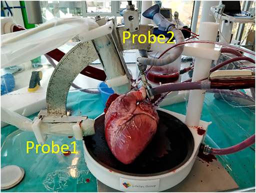
In the ex-vivo experimental setup, a porcine heart was paced at a rate between 90 and 120 beats per min (bmp) to assure a steady heart rhythm through the whole experiment (see Figure 1). The heart was entirely submerged in a saline solution at 38°C in order to perform US imaging. More details about the setup of the beating porcine heart can be found in [28, 29], where a similar design was used.
US Data were acquired using a 256-channel Vantage open research system (Verasonics, Redmond, United States) equipped with two phased array probes (type: P4-2v, center frequency: 2.95 MHz, bandwidth: 1.64–4.26 MHz).
The two probes were attached to a mini-arch that ensures that they were exactly aligned in the same imaging plane, as can be seen in Figure 1. The arch allows to adjust the relative angle between the probes, as well as the probe positions in the radial direction to adjust the distances with respect to the heart. Probe 1 (P1) was positioned to acquire the parasternal short axis view, while the second probe (P2) was rotated every 15° from 30° to 75° with respect to the first probe on the mini-arch. All US data were acquired at a frame rate of 170 FPS, which was more than 3 times higher than conventional cardiac US imaging (<50 FPS). The two probes acquired US data in an interleaved scanning scheme, where they took turns to transmit and receive diverging waves under 11 steering angles between -12° and 12°, i.e., the angle of the virtual sources with respect to the center of the aperture. US data were compounded in receive mode to improve image quality at the cost of a lower frame rate.
The frame rate Fr of the multi-perspective ultrafast imaging system is calculated as follows:
where
During the acquisition, all the channel data (raw US data) of each probe were sampled at four times the effective center frequency. All 320 frames of the acquired raw US data were reconstructed and stored as in-phase quadrature (IQ) data before envelope detection in MATLAB R2019a (The MathWorks, Natick, MA, United States) for further offline processing.
Image Registration and Fusion
Temporal registration was not required since the US images from the two separate probes were obtained in an interleaved scanning sequence. A fully automatic spatial registration method was developed to align the images (after envelope detection) of all different relative angles (30°–75°) acquired by the multi-perspective ultrafast imaging system.
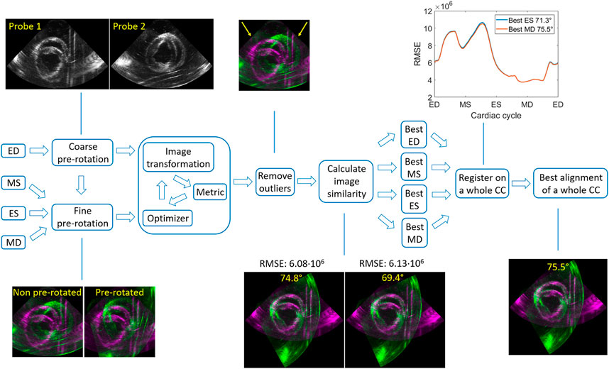
Four frames in the cardiac cycle of the 75° dataset (ED: end of diastole, MS: mid of systole, ES: end of systole, MD: mid of diastole) were selected to demonstrate the algorithm (see Figure 2). First, the ED was used to perform a coarse pre-rotation, where the image obtained with probe 2 (P2) was rotated every 10° from 10° to 90° with respect to the image acquired with probe 1 (P1). Next, these ten pre-rotated P2 images were registered to P1 by an image intensity based optimization algorithm [30], yielding a global rotation angle.
The iterative process of the optimization algorithm started with generating the initial transformation matrix based on the initial condition of the two images. Next, the metric compared the transformed moving image (P2) to the fixed image (P1) and create a metric value. Finally, the optimizer checked the stop condition based on the metric value and adjusted the transformation matrix for the next iteration. The process terminated when the metric approached a point of diminishing returns or when the number of maximum iterations was reached. The optimizer was based on a one-plus-one evolutionary algorithm (growth factor: 1.05, epsilon: 1.5, initial radius: 0.0063, maximum iterations: 100) and the metric used was the mutual information of the two images [31, 32].
Next, outliers were removed by calculating the overlapping percentage of the field-of-views (the sector/fan shapes) for the registered ten image sets. When the overlapping percentage of the two field-of-views was larger than 90%, it was considered to be an outlier (Figure 2). The score of the best alignment for ED was based on calculating the root mean square error (RMSE) of the gray values, where the lowest RMSE determined the best alignment of the ten registration results.
Three more frames (MS, ES and MD) in a whole cardiac cycle were chosen to repeat the previous steps applied on ED. To decrease the computation time, a fine pre-rotation was performed instead of the coarse pre-rotation, using the best three pre-rotation angles derived from the lowest RMSE values in ED. Similarly, the best alignments for these three frames were obtained (as Figure 2 shows).
Finally, all these four best alignments (ED, MS, ES, MD) were registered on a whole cardiac cycle, where the lowest mean of RMSE determined the best alignment of the whole cardiac cycle.
A fusion algorithm based on the discrete wavelet transform (DWT) was adapted to fuse the US images obtained from the two probes with different relative angles [33, 34]. The Haar wavelet is commonly used in image processing due to its fast and orthogonal properties [35–37]. It was selected to decompose the images into 2 layers with 7 subbands (see Figure 3). The fusion rules applied on DWT were defined as follows: for low frequency subband LL2 which encompasses the structures of the left ventricular wall, the maximum values of the two images were taken. High frequency subbands (LH, HL and HH) show small structures, e.g., the noise and speckles, in the US images. Hence, for these subbands, averaging was performed. Finally, after fusion, all the subbands were reconstructed into one fused image.

FIGURE 3. An example of DWT decomposition using 2 layers: the low horizontal and vertical high subbands (LH2, LH1) (left two images); the low frequency subband LL2 (right).
Speckle Tracking
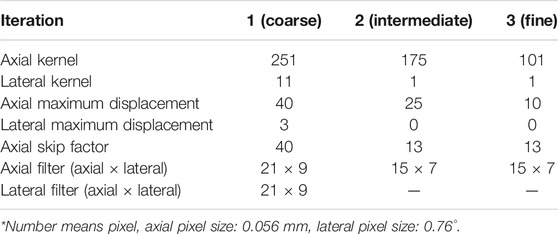
The speckle tracking algorithm encompasses a 2-D block matching method that calculates the normalized cross-correlation as an index of similarity between frames to determine displacements in both axial and lateral directions of the US sector grid during a full cardiac cycle [38]. First, US envelope data were used to obtain coarse displacements in both directions. After median filtering, these coarse displacements were used as input for the next iteration step (intermediate) to refine the displacements, where a smaller kernel size was applied on RF data instead. Next, in the third iteration (fine), the fine displacements are estimated. The parameters used for speckle tracking are shown in Table 1. RF data were chosen to perform speckle tracking since the resolution and precision are significantly better than B-mode speckle tracking [39]. Speckle tracking was performed separately on the RF datasets of the dual probes.
The myocardium was segmented in the fused B-mode image at the end-of-diastole frame (ED) by manually selecting the inner (endocardium-myocardium) and outer (epicardium-myocardium) walls. Considering the non-conventional nature of the data, automatic segmentation algorithms were not considered. Based on the result of automatic registration, the segmented mesh of the fused image was converted to meshes for the images obtained by the single probes. The segmented mesh consisted of 11 by 90 samples in the radial and circumferential directions, respectively. The mesh was tracked over the cardiac cycle using the displacements estimated by the speckle tracking algorithm to estimate myocardial motion [38].
Displacement Compounding and Strain Estimation
To compound the displacements, benefitting fully from the multi-perspective imaging data, two different methods were considered. The first compounding method used in this study to improve strain estimation is unit axial vector compounding (VC). The fine axial displacements were compounded based on the unit axial vectors of the dual probes to improve the motion tracking of the myocardium for all relative angle datasets. Lateral displacements were discarded, given the relatively poor accuracy compared to axial displacements. Hence, 2-D kernels were only used to correct for lateral motion to improve axial displacement estimates. The axial displacements of P2 were transformed and interpolated into the polar coordinates of P1, allowing for axial displacement compounding.
As Figure 4 shows, the true direction of the red point in the tracking mesh is decomposed into the axial and lateral directions. Therefore, the estimated true displacement can be represented using unit axial vectors and axial displacements of the dual probes:
where
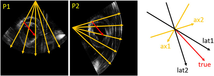
FIGURE 4. Vector representation. An example (relative angle 75°) in the tracking mesh is shown (red point), where orange (ax1, ax2), black (lat1 and lat2) and red (true) arrows represent axial, lateral and true directions, respectively.
Since Eq. 2 consists of a system of two linear equations with two unknowns, a unique solution of the true displacement
where
Strain Fusion
The second method to improve strain estimation is to fuse the strain instead of compounding the displacements, so-called strain fusion (SF). Derived radial and circumferential strain of the two probes for all relative angle datasets were fused based on automatically generated strain fusion masks. In the first step, for each point in the segmentation mesh (11 by 90 samples in total), the angle between strain and US beam direction was calculated for both probes. Next, all the calculated angles in the mesh of the two probes were compared, where the smaller angles were selected to create the masks for strain fusion. Finally, as Figure 5 shows, the masks for radial and circumferential strain fusion were created, where cyan shows strain selected from probe 1 (P1) and yellow indicates strain chosen from probe 2 (P2). Furthermore, the mesh was segmented into six regions for regional strain analysis [42].

FIGURE 5. Strain fusion: an example on how to select the optimal radial strain from the two probes for in this case a relative angle of 75° (left two images). The orange arrows indicate the US beam directions, the red arrows indicate the radial strain direction of the red point for the two probes respectively.
Analysis of Results
To quantify the accuracy of the registration results, the rotation error was calculated with respect to the ground truth derived from the mini-arch.
To compare the motion tracking performance between single-perspective (SP) and multi-perspective using VC, the mean error (ME) of the entire tracking mesh was estimated between the last (ED) and first frame (ED) of a tracking cycle:
where n is the number of pixels in the tracking mesh,
The elastographic signal-to-noise ratio (SNRe) at the end-systolic radial and circumferential strain were calculated to analyze the strain estimation for SP, and multi-perspective VC and SF:
where
The mean drift error (MDE) and strain variability (SV) of radial and circumferential strain were calculated for the last frame, since MDE and SV should theoretically be zero at the end of a tracking cycle:
where
Results
Registration
The fully automatic registration method was tested for all different angle datasets (30°–75°) for three cardiac cycles, as Figure 6 shows. In all cases, the best alignment was found when the pre-rotation angle applied was < ± 15° with respect to the true angle. Overall, final registration result revealed a mean rotation error of 1.4° with respect to the ground truth (angle set on the arch).
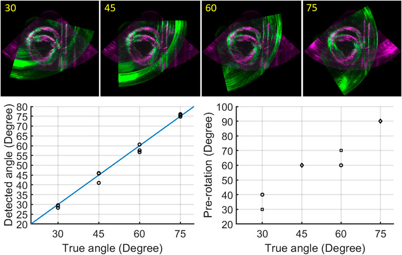
FIGURE 6. Registration results: registered image data for angles ranging from 30° to 75° (top row); true angle versus detected angles, black circles indicate three different cardiac cycles (bottom left); true angle versus pre-rotation angles (circle: one cardiac cycle, square: two cardiac cycles, diamond: three cardiac cycles) (bottom right).
Motion Tracking
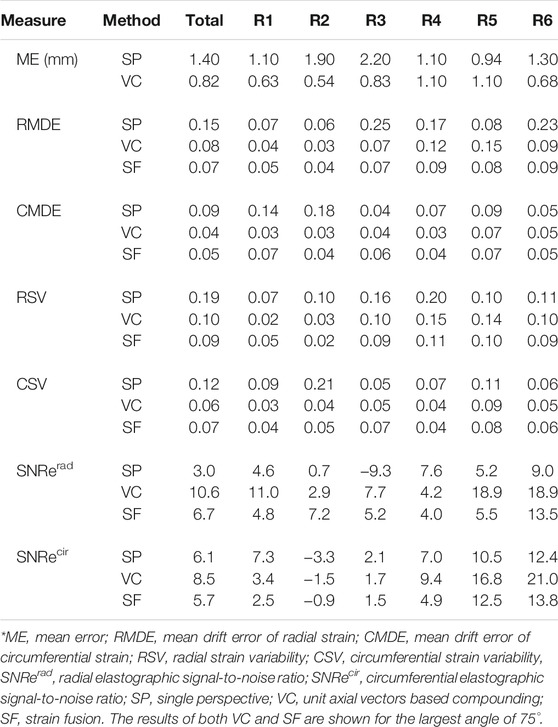
Figure 7 shows the performance of motion tracking at the end of a cardiac cycle. More quantitative results of the mean error for motion tracking are demonstrated in Table 2. The myocardium contours of SP show that the myocardium coordinates are more uniformly distributed in the upper wall regions (R4, R5). This coincides with motion tracking performing better in the axial direction where the ultrasound beams propagate. While increasing the imaging depth, the lateral resolution decreases accordingly, leading to a reduced tracking accuracy (R2) with an error drift of 1.9 mm. In the side wall regions (R6, R3), where the wall motion is mainly occurring in the lateral direction, the error drift increases by 0.3 and 0.9 mm, respectively.
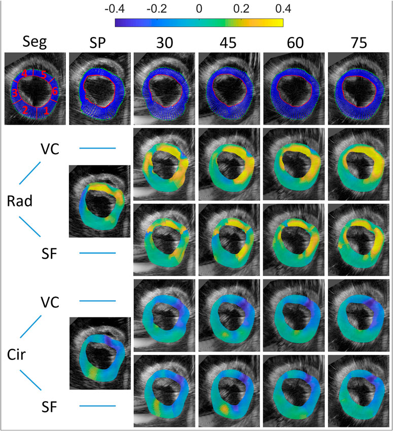
FIGURE 7. Motion tracking and end-systolic strain for all multi-perspective datasets (relative angles 30°–75°). Top row: the initial segmentation mesh (first frame), and final tracked meshes at end-diastole are shown (SP and 30°–75°). Both radial and circumferential end-systolic strain images are shown for single-perspective imaging (SP), and multi-perspective strain imaging using unit axial vectors based compounding (VC) and strain fusion (SF), respectively.
After unit axial vector based compounding, with the largest angle 75° (as Figure 7 top right shows), the tracking mesh (at the last frame) shows the most similar shape as the segmentation mesh shows (see Figure 7 top left). The mean error reduces from 1.4 to 0.82 mm in total, with the largest reduction found at side wall region (R3, reduction of 1.37 mm) and lower wall (R2, reduction of 1.36 mm). This can be appreciated by the reduction of lateral drift compared to single probe imaging.
Strain Estimation
End-systolic strain are shown for single perspective, unit axial vector based compounding and strain fusion in Figure 7. MDE, SV and SNRe were calculated for both radial and circumferential strain using these three methods, as can be seen in Table 2.
For radial strain, an average radial strain of 0.08 ± 0.05 was measured in single perspective strain imaging. The largest positive strain values are found at the regions of the myocardium where radial strain is estimated from mostly the axial displacements (R4, R5), and the SNRe reaches up to 7.6. In the lateral regions of the myocardium (R3, in the middle of R1 and R6), where the deformations are perpendicular to the direction of US wave, negative strain occur with a low SNRe of −9.3, caused by the inaccurate lateral displacement estimates used. After VC (largest angle 75°), the overall radial strain reaches up to 0.20 ± 0.07 and the SNRe increases from 3.0 to 10.6. The largest strain values (0.35) are found in R5 and R6 with the highest SNRe of 18.9 in all regions. The largest improvement of SNRe (increases from −9.3 to 7.7) is found at R3. A similar trend is shown in the SNRe after SF (largest angle 75°), despite only a small improvement (over SP) with respect to VC, in terms of the maximum strain value and SNRe. Compared to single perspective strain imaging, the overall radial strain measured is 0.17 ± 0.05 and the SNRe increases from 3.0 to 6.7 after SF. The largest improvement of SNRe (increases from −9.3 to 5.2) is also found at R3, where single perspective strain imaging performed worst, caused by the inaccurate lateral displacements.
For circumferential strain, an average circumferential strain of −0.09 ± 0.03 was estimated in single perspective strain imaging. The largest negative strain values are found at R5 and R6, and strain precision is higher where the strain direction are equal to the US beam propagation (R6, R3), with the largest SNRe found to equal 12.4 (R6). In the lateral region with a large depth (R2), where the strain estimation mostly relied on the lateral displacements with the lowest resolution, a positive strain value of 0.06 and the lowest SNRe of −3.3 are found. After VC (largest angle 75°), the overall circumferential strain reaches up to −0.12 ± 0.03 and SNRe increases from 6.1 to 8.5. The largest strain value increases from 0.27 to 0.30 in R5 and the highest SNRe of 21.0 is found in R6. In the lateral regions (R2, R5), a large increase of SNRe (increase of 6.3) is shown in R5, while only a small increase of SNRe (increase of 1.8) in R2. After SF (largest angle 75°), improvements of SNRe are shown in R2, R5 (lateral regions for single perspective) and R6, despite a small decrease of overall SNR (decrease of 0.4).
The mean drift error (MDE) and strain variability (SV) of radial and circumferential strain were calculated for the last frame, as can be depicted from Table 2 and Figure 8. Overall, no significant differences were found between VC and SF for MDE and SV. After VC (largest angle 75°), the mean drift error decreases 0.07 and 0.05 for radial and circumferential strain, respectively. The largest improvements for radial strain are found in R3 and R6, where strain directions are perpendicular to the US beam directions (for single perspective). Similarly, extensive improvements for circumferential strain are found in R1 and R2. Strain variability reduces by 0.08 for both strain components on average. For radial strain, a large reduction of 0.06 is shown in R3 as expected. A similar trend is shown for circumferential strain with a decrease of 0.17 in R2.
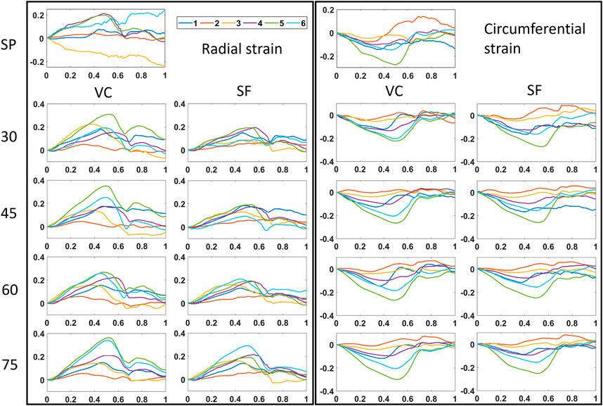
FIGURE 8. Time strain curves for all multi-perspective datasets (30°–75°). Both radial and circumferential strain curves are shown for single-perspective imaging (SP), and multi-perspective, unit axial vectors based compounding (VC) and strain fusion (SF), respectively.
Discussion
This study explored the benefits and feasibility of using multi-perspective ultrafast US to improve cardiac strain imaging. More specifically, the improvements in myocardial strain were investigated when positioning the dual probes at different relative angles and using different strain compounding methods, in an ex-vivo beating porcine heart setup. A fully automatic registration algorithm was developed to accurately align the two image datasets acquired from the dual probes for all different angle cases. A novel axial displacement compounding method based on unit axial vectors was proposed to improve the cardiac strain estimation for both strain components, and was compared to a strain fusion algorithm and conventional single probe strain imaging to quantitatively compare the improvements of strain estimation. Furthermore, a quantitative comparison of inter-probe angle for multi-perspective ultrafast US imaging was demonstrated, in terms of improvements in motion tracking and strain estimation.
The mini-arch was designed for experimental verification purposes only, not for in vivo use. In future in vivo studies, it would be difficult to rotate the second probe on the mini-arch as we did in this ex-vivo study, given the imaging windows are limited and ribs are present. Ultimately, the technique could be used in vivo by mounting two probes onto the subject’s thorax, allowing multi-perspective imaging in a freehand fashion. With this in mind, an automatic image registration algorithm was developed.
To cope with the large rotation, anisotropic resolution, and regional contrast differences from the two different perspectives in this application, a good initial condition needs to be provided before the optimization algorithm operated. This was done by an automatic pre-rotation step, where the moving image (P2) was pre-rotated in a step of 10° from 10° to 90° with respect to the fixed image (P1). The registration algorithm performed well but results do indicate that an initial estimate of the inter-probe rotation angle (<±15° with respect to the true angle, see Figure 6) is required. To decrease the computation time, this pre-rotation angle could be estimated in clinical practice by a simple mechanical sensor mounted to the probe.
Since no temporal registration was required in this study, the two image sets of a whole cardiac cycle can be registered by applying the registration result of any frame during a whole cardiac cycle. Four frames were selected for registration to ensure the accuracy and efficiency of the registration process. More importantly, the algorithm we developed determined the best registration automatically by calculating the RMSE of the two images in a whole cardiac cycle without using the ground truth from the arch. The results of the fully automatic registration algorithm revealed a rotation error of 1.4° in all cases, indicating good agreement for different datasets (different cardiac cycles and angles). The largest rotation bias (4.0°) with respect to the ground truth was found when the inter-probe angle was 45°, mainly caused by the inaccurate selection among the best four alignments for a whole cardiac cycle. This can be explained by the extensive artifacts, which were present in the image acquired by P2 near the boundaries of the overlapping regions (green image of 45° in Figure 6). These artifacts were created by the supporting devices for the beating porcine heart and the strong reflection from the bottom of the tank. In this case, the lowest RMSE (7.35.106) of the two images failed to represent the best alignment, since the registration result with more of these artifacts appearing inside the overlapping regions will obtain a lower score for RMSE. In the datasets of other angles, less artifacts were present around the boundaries of the overlapping regions. Therefore, the scores of RMSE for these cases were less sensitive to the small shift of artifacts occurring in the best four alignments, leading to more accurate registration results. It goes without saying that the presence of these artifacts affects the accuracy of the registration. In vivo, these artifacts will not appear, although there near field clutter will be present caused by neighboring structures such as the ribs. A possible solution to make the selection of the best alignment more accurate would be only calculating the RMSE for the region of interest, i.e., the LV. However, this requires a dedicated automatic segmentation algorithm to precisely segment out the LV, which will unavoidably and extensively increase the computation time.
For motion tracking, one may notice that the maximum lateral displacement for the second and third iterations of speckle tracking were set to zero (see Table 1), which means only in the first step, lateral displacement estimates contributed to motion tracking and strain estimation. By doing so, numerous accumulated lateral drift errors caused by the poor lateral resolution and high number of frames from the last two iteration steps were reduced, although the tracking became insufficient and inaccurate in the lateral direction (as Figure 7 shows). After compounding the axial displacements of the two probes (largest angle 75°), the performance of motion tracking improved vastly compared to single probe imaging, the error drift reduced 40% on average, with the largest reduction found at the side wall regions (R3, R6). The tracking mesh showed a more similar shape as the segmentation mesh showed.
A quantitative comparison between different relative angle datasets using VC is shown in Figure 9. Overall, after VC, all inter-probe angles show improvements in terms of motion tracking, SNRe, MDE, SV, strain magnitudes and strain curves over SP (also see Figures 7, 8 and Table 2). While increasing the inter-probe angle from 30° to 75°, ME, MDE and SV decrease and SNRe increases for both strain components, with the largest difference found for angles ≥60°. For the largest angle (75°), ME (-42%), MDE (-50%) and SV (-48%) reduce significantly, SNRe increases by 253 and 39% for radial and circumferential strain, respectively, and strain curves reveal less noise for each region. The investigation of inter-probe angle shows that motion tracking and strain estimation improve when the angle increases. For future in vivo measurements, one should aim for a large angle to benefit the most, ideally 90°. Due to the presence of ribs and limited imaging windows, this remains challenging and still needs to be validated. However, in some cases, when only a small inter-probe angle might be feasible (30°–60°), motion tracking and strain estimation can still be improved when using VC compounding (see Figures 7–9).

FIGURE 9. Comparison between different relative angle datasets using multi-perspective unit axial vectors based compounding (VC). The Mean error (ME) of the tracking performance (left), the mean drift error (MDE) and strain variability (SV) of radial and circumferential strain at end-diastole (middle), the elastographic signal-to-noise ratio (SNRe) at the end-systolic radial and circumferential strain (right).
This study introduced a unit axial vector based displacement compounding method to improve motion tracking and strain estimation. The advantages of VC over SF have been quantitatively illustrated in terms of SNRe, MDE, SV, strain magnitudes and strain curves for both strain components. This can be explained by the fact that VC only uses axial displacements to derive strain while SF includes a certain contribution of lateral displacements. It is generally known that due to a lack of phase information and a lower resolution in the lateral direction, strain derived from the lateral displacements are less accurate than derived from the axial displacements [43, 44]. Especially, in the intersections of strain fusion masks (see Figure 5, intersections of cyan and yellow), the angles between strain direction and US beam direction for both probes are larger than 45°, which means more than 50% lateral displacements are used to derive strain in these regions. Although SF shows improvement over SP in all aspects, the fact of using lateral displacements to derive strain makes it less accurate than VC which only uses axial displacements to derive strain [41, 45, 46].
The method of unit axial vectors based displacement compounding we proposed is straightforward and solves the true displacements with a unique solution using two axial displacement datasets acquired by the dual probes. It certainly has merit for in vivo, high quality strain imaging. Conventional single probe beam steering, as shown in, e.g. carotid imaging, are not sufficient at these depths with phased array transducers. Of course, the use of two probes will make an in vivo examination more complex, although probe mounting (possibly in a more dedicated arch with more flexibility that ensures common image planes) or passive robotic devices could assist in the exam. Ultimately, for in vivo application, the methods introduced in this paper should be extended to 3-D, which will make precise probe alignment less of a bottleneck.
In vivo interleaved multi-perspective US strain imaging, however, will still require extensive US safety testing and ethical approval, as well as a step to handheld or partially mounted dual probe imaging in 3-D as explained earlier. Once this is achieved, multi-perspective US strain imaging could play an indispensable role in the diagnosis and management of virtually any disease that affects the myocardium. Future studies will focus on performing multi-perspective ultrafast US myocardial strain imaging in vivo. The improved motion tracking and myocardial strain estimation could provide a more sensitive means for detecting regional myocardial dysfunction, and improve the reliability of strain estimation for the heart in general, thereby boosting the use and diagnostic value of cardiac strain imaging in general.
Data Availability Statement
The original contributions presented in the study are included in the article/Supplementary Material, further inquiries can be directed to the corresponding author.
Ethics Statement
The animal study was reviewed and approved by Dutch Ministry of Agriculture, Nature and Food Quality, and Food and Consumer Product Safety Authority.
Author Contributions
PL has setup experiments, performed data acquisition, developed algorithms, analyzed data, created the manuscript. J-WM has played a significant role in the development of the unit vector axial projection method. H-MS has collaborated on US acquisition methods, data analysis and manuscript writing. RL is responsible for the study design, helped in algorithm development, data analysis and interpretation, manuscript writing, and obtaining study funding.
Funding
This work is part of the MUSE project, which has received funding from the European Research Council (ERC) under the European Union’s Horizon 2020 research and innovation program (ERC starting grant 757958).
Conflict of Interest
The authors declare that the research was conducted in the absence of any commercial or financial relationships that could be construed as a potential conflict of interest.
Publisher’s Note
All claims expressed in this article are solely those of the authors and do not necessarily represent those of their affiliated organizations, or those of the publisher, the editors and the reviewers. Any product that may be evaluated in this article, or claim that may be made by its manufacturer, is not guaranteed or endorsed by the publisher.
Acknowledgments
The efforts by Jurgen Bulsink (Eindhoven University of Technology, Eindhoven, Netherlands) in building the mini-arch for the ex-vivo measurements are kindly acknowledged.
References
1. Ho CY, Carlsen C, Thune JJ, Havndrup O, Bundgaard H, Farrohi F, et al. Echocardiographic Strain Imaging to Assess Early and Late Consequences of Sarcomere Mutations in Hypertrophic Cardiomyopathy. Circ Cardiovasc Genet (2009) 2(4):314–21. doi:10.1161/circgenetics.109.862128
2. Artis NJ, Oxborough DL, Williams G, Pepper CB, Tan LB. Two-dimensional Strain Imaging: A New Echocardiographic advance with Research and Clinical Applications. Int J Cardiol (2008) 123(3):240–8. doi:10.1016/j.ijcard.2007.02.046
3. Gorcsan J, Tanaka H. Echocardiographic Assessment of Myocardial Strain. J Am Coll Cardiol (2011) 58(14):1401–13. doi:10.1016/j.jacc.2011.06.038
4. Gjesdal O, Hopp E, Vartdal T, Lunde K, Helle-Valle T, Aakhus S, et al. Global Longitudinal Strain Measured by Two-Dimensional Speckle Tracking Echocardiography Is Closely Related to Myocardial Infarct Size in Chronic Ischaemic Heart Disease. Clin Sci (2007) 113(6):287–96. doi:10.1042/cs20070066
5. Collier P, Phelan D, Klein A. A Test in Context: Myocardial Strain Measured by Speckle-Tracking Echocardiography. J Am Coll Cardiol (2017) 69(8):1043–56. doi:10.1016/j.jacc.2016.12.012
6. Maffessanti F, Nesser H-J, Weinert L, Steringer-Mascherbauer R, Niel J, Gorissen W, et al. Quantitative Evaluation of Regional Left Ventricular Function Using Three-Dimensional Speckle Tracking Echocardiography in Patients with and without Heart Disease. Am J Cardiol (2009) 104(12):1755–62. doi:10.1016/j.amjcard.2009.07.060
7. Kiss G, Nielsen E, Orderud F, Torp HG. Performance Optimization of Block Matching in 3D Echocardiography. In: 2009 IEEE International Ultrasonics Symposium; September 20, 2009; Italy, Rome (2009). p. 1403–6.
8. Sitia S, Tomasoni L, Turiel M. Speckle Tracking Echocardiography: A New Approach to Myocardial Function. World J Cardiol (2010) 2(1):1–5. doi:10.4330/wjc.v2.i1.1
9. Dandel M, Hetzer R. Echocardiographic Strain and Strain Rate Imaging - Clinical Applications. Int J Cardiol (2009) 132(1):11–24. doi:10.1016/j.ijcard.2008.06.091
10. Joos P, Porée J, Liebgott H, Vray D, Baudet M, Faurie J, et al. High-Frame-Rate Speckle-Tracking Echocardiography. IEEE Trans Ultrason Ferroelect Freq Contr (2018) 65(5):720–8. doi:10.1109/tuffc.2018.2809553
11. Provost J, Papadacci C, Arango JE, Imbault M, Fink M, Gennisson J-L, et al. 3D Ultrafast Ultrasound Imagingin Vivo. Phys Med Biol (2014) 59(19):L1–L13. doi:10.1088/0031-9155/59/19/l1
12. Cikes M, Tong L, Sutherland GR, D'hooge J. Ultrafast Cardiac Ultrasound Imaging. JACC Cardiovasc Imaging (2014) 7(8):812–23. doi:10.1016/j.jcmg.2014.06.004
13. Villemain O, Baranger J, Friedberg MK, Papadacci C, Dizeux A, Messas E, et al. Ultrafast Ultrasound Imaging in Pediatric and Adult Cardiology: Techniques, Applications, and Perspectives. JACC Cardiovasc Imaging (2020) 13(8):1771–91. doi:10.1016/j.jcmg.2019.09.019
14. Ramalli A, Dallai A, Boni E, Bassi L, Meacci V, Giovannetti M, et al. Multi Transmit Beams for Fast Cardiac Imaging towards Clinical Routine. In: 2016 IEEE International Ultrasonics Symposium (IUS); September 18, 2016; France, Tours (2016). p. 1–4.
15. Tong L, Gao H, D'hooge J. Multi-transmit Beam Forming for Fast Cardiac Imaging-A Simulation Study. IEEE Trans Ultrason Ferroelect Freq Contr (2013) 60(8):1719–31. doi:10.1109/tuffc.2013.2753
16. Zurakhov G, Tong L, Ramalli A, Tortoli P, D'hooge J, Friedman Z, et al. Multiline Transmit Beamforming Combined with Adaptive Apodization. IEEE Trans Ultrason Ferroelect Freq Contr (2018) 65(4):535–45. doi:10.1109/tuffc.2018.2794219
17. Montaldo G, Tanter M, Bercoff J, Benech N, Fink M. Coherent Plane-Wave Compounding for Very High Frame Rate Ultrasonography and Transient Elastography. IEEE Trans Ultrason Ferroelect Freq Contr (2009) 56(3):489–506. doi:10.1109/tuffc.2009.1067
18. Denarie B, Tangen TA, Ekroll IK, Rolim N, Torp H, Bjåstad T, et al. Coherent Plane Wave Compounding for Very High Frame Rate Ultrasonography of Rapidly Moving Targets. IEEE Trans Med Imaging (2013) 32(7):1265–76. doi:10.1109/tmi.2013.2255310
19. Szmigielski C, Rajpoot K, Grau V, Myerson SG, Holloway C, Noble JA, et al. Real-Time 3D Fusion Echocardiography. JACC Cardiovasc Imaging (2010) 3(7):682–90. doi:10.1016/j.jcmg.2010.03.010
20. Yao C, Simpson JM, Schaeffter T, Penney GP. Multi-view 3D Echocardiography Compounding Based on Feature Consistency. Phys Med Biol (2011) 56(18):6109–28. doi:10.1088/0031-9155/56/18/020
21. Rajpoot K, Grau V, Noble JA, Szmigielski C, Becher H. Multiview Fusion 3-d Echocardiography: Improving the Information and Quality of Real-Time 3-D Echocardiography. Ultrasound Med Biol (2011) 37(7):1056–72. doi:10.1016/j.ultrasmedbio.2011.04.018
22. Mulder HW, van Stralen M, van der Zwaan HB, Leung KY, Bosch JG, Pluim JP. Multiframe Registration of Real-Time Three-Dimensional Echocardiography Time Series. J Med Imaging (Bellingham) (2014) 1:014004. doi:10.1117/1.JMI.1.1.014004
23. Augustine D, Yaqub M, Szmigielski C, Lima E, Petersen SE, Becher H, et al. “3D Fusion” Echocardiography Improves 3D Left Ventricular Assessment: Comparison with 2D Contrast Echocardiography. Echocardiography (2015) 32(2):302–9. doi:10.1111/echo.12655
24. Haak A, Ren B, Mulder HW, Vegas-Sánchez-Ferrero G, van Burken G, van der Steen AFW, et al. Improved Segmentation of Multiple Cavities of the Heart in Wide-View 3-D Transesophageal Echocardiograms. Ultrasound Med Biol (2015) 41(7):1991–2000. doi:10.1016/j.ultrasmedbio.2015.03.011
25. Peralta L, Gomez A, Luan Y, Kim B-H, Hajnal JV, Eckersley RJ. Coherent Multi-Transducer Ultrasound Imaging. IEEE Trans Ultrason Ferroelect Freq Contr (2019) 66(8):1316–30. doi:10.1109/tuffc.2019.2921103
26. de Hoop H, Petterson NJ, van de Vosse FN, van Sambeek MRHM, Schwab H-M, Lopata RGP. Multiperspective Ultrasound Strain Imaging of the Abdominal Aorta. IEEE Trans Med Imaging (2020) 39(11):3714–24. doi:10.1109/tmi.2020.3003430
27. van Hal VHJ, De Hoop H, Muller JW, van Sambeek MRHM, Schwab H-M, Lopata RGP. Multiperspective Bistatic Ultrasound Imaging and Elastography of the Ex Vivo Abdominal Aorta. IEEE Trans Ultrason Ferroelect Freq Contr (2022) 69(2):604–16. doi:10.1109/tuffc.2021.3128227
28. de Hart J, de Weger A, van Tuijl S, Stijnen JMA, van den Broek CN, Rutten MCM, et al. An Ex Vivo Platform to Simulate Cardiac Physiology: A New Dimension for Therapy Development and Assessment. Int J Artif Organs (2011) 34(6):495–505. doi:10.5301/ijao.2011.8456
29. Petterson NJ, Fixsen LS, Rutten MCM, Pijls NHJ, van de Vosse FN, Lopata RGP. Ultrasound Functional Imaging in Anex Vivobeating Porcine Heart Platform. Phys Med Biol (2017) 62(23):9112–26. doi:10.1088/1361-6560/aa9515
30. Lee M, Kim S, Seo I. Intensity-based Registration of Medical Images. In: 2009 International Conference on Test and Measurement; December 5, 2009; China, Hong Kong (2009). p. 239–42.
31. Styner M, Brechbuhler C, Szckely G, Gerig G. Parametric Estimate of Intensity Inhomogeneities Applied to MRI. IEEE Trans Med Imaging (2000) 19(3):153–65. doi:10.1109/42.845174
32. Raghunathan S, Stredney D, Schmalbrock P, Clymer BD. Image Registration Using Rigid Registration and Maximization of Mutual Information. In: 13th Annu. Med. Meets Virtual Reality Conf; Jan 26, 2005; Long Beach, United States (2000).
33. Geng P, Sun X, Liu J. Adopting Quaternion Wavelet Transform to Fuse Multi-Modal Medical Images. J Med Biol Eng (2017) 37(2):230–9. doi:10.1007/s40846-016-0200-6
34. Singh R, Vatsa M, Noore A. Multimodal Medical Image Fusion Using Redundant Discrete Wavelet Transform. In: 2009 Seventh International Conference on Advances in Pattern Recognition; February 4, 2009; India, Kolkata (2009). p. 232–5.
35. Ajwad AA. Noise Reduction of Ultrasound Image Using Wiener Filtering and Haar Wavelet Transform Techniques. DJM (2012) 2(1):91–100.
36. Zhou S, Shi J, Zhu J, Cai Y, Wang R. Shearlet-based Texture Feature Extraction for Classification of Breast Tumor in Ultrasound Image. Biomed Signal Process Control (2013) 8(6):688–96. doi:10.1016/j.bspc.2013.06.011
37. Stanković RS, Falkowski BJ. The Haar Wavelet Transform: its Status and Achievements. Comput Electr Eng (2003) 29(1):25–44. doi:10.1016/S0045-7906(01)00011-8
38. Lopata RGP, Nillesen MM, Hansen HHG, Gerrits IH, Thijssen JM, de Korte CL. Performance Evaluation of Methods for Two-Dimensional Displacement and Strain Estimation Using Ultrasound Radio Frequency Data. Ultrasound Med Biol (2009) 35(5):796–812. doi:10.1016/j.ultrasmedbio.2008.11.002
39. Ma C, Varghese T. Comparison of Cardiac Displacement and Strain Imaging Using Ultrasound Radiofrequency and Envelope Signals. Ultrasonics (2013) 53(3):782–92. doi:10.1016/j.ultras.2012.11.005
40. Lopata RGP, Hansen HHG, Nillesen MM, Thijssen JM, De Korte CL. Comparison of One-Dimensional and Two-Dimensional Least-Squares Strain Estimators for Phased Array Displacement Data. Ultrason Imaging (2009) 31(1):1–16. doi:10.1177/016173460903100105
41. Hansen H, Lopata R, de Korte CL. Noninvasive Carotid Strain Imaging Using Angular Compounding at Large Beam Steered Angles: Validation in Vessel Phantoms. IEEE Trans Med Imaging (2009) 28(6):872–80. doi:10.1109/tmi.2008.2011510
42. D'hooge J, Heimdal A, Jamal F, Kukulski T, Bijnens B, Rademakers F, et al. Regional Strain and Strain Rate Measurements by Cardiac Ultrasound: Principles, Implementation and Limitations. Eur J Echocardiogr (2000) 1(3):154–70. doi:10.1053/euje.2000.0031
43. Techavipoo U, Chen Q, Varghese T, Zagzebski JA. Estimation of Displacement Vectors and Strain Tensors in Elastography Using Angular Insonifications. IEEE Trans Med Imaging (2004) 23(12):1479–89. doi:10.1109/tmi.2004.835604
44. Hansen HHG, Lopata RGP, Idzenga T, de Korte CL. An Angular Compounding Technique Using Displacement Projection for Noninvasive Ultrasound Strain Imaging of Vessel Cross-Sections. Ultrasound Med Biol (2010) 36(11):1947–56. doi:10.1016/j.ultrasmedbio.2010.06.008
45. Hansen HHG, Idzenga T, de Korte CL. Noninvasive Vascular Strain Imaging: from Methods to Application. Curr Med Imaging Rev (2012) 8(1):37–45. doi:10.2174/157340512799220607
Keywords: ultrasound imaging, multi-perspective ultrasound, ultrafast imaging, cardiac strain imaging, image registration, strain fusion
Citation: Liu P, Muller J-, Schwab H- and Lopata R (2022) Cardiac Strain Imaging Using Multi-Perspective Ultrafast Ultrasound. Front. Phys. 10:789263. doi: 10.3389/fphy.2022.789263
Received: 04 October 2021; Accepted: 02 February 2022;
Published: 03 March 2022.
Edited by:
Simon Chatelin, UMR7357 Laboratoire des sciences de l’Ingénieur, de l’Informatique et de l’Imagerie (ICube), FranceReviewed by:
Jan Kober, Institute of Thermomechanics (ASCR), CzechiaWei-Ning Lee, The University of Hong Kong, Hong Kong SAR, China
Copyright © 2022 Liu, Muller, Schwab and Lopata. This is an open-access article distributed under the terms of the Creative Commons Attribution License (CC BY). The use, distribution or reproduction in other forums is permitted, provided the original author(s) and the copyright owner(s) are credited and that the original publication in this journal is cited, in accordance with accepted academic practice. No use, distribution or reproduction is permitted which does not comply with these terms.
*Correspondence: Peilu Liu, cC5saXU0QHR1ZS5ubA==
 Peilu Liu
 Jan-Willem Muller