- Optoelectronics Laboratory, Department of Electrical and Information Engineering, Politecnico di Bari, Bari, Italy
Synthetic aperture radar (SAR) systems employ a Linearly Chirped Microwave Waveform Generator (LCMWG) with large time–bandwidth product (TBWP), to provide a wide range resolution. Photonics has now been recognized as a disruptive approach to achieve high performance at bandwidth of few tens of gigahertz, with light and compact architectures, due to the typical photonics benefits, such as electromagnetic interference immunity, small power consumption, small footprint, and high immunity to vibration/shock and radiation. In this article, we report on the photonic generation of a high-frequency LCMW, with a large TBWP (102–103), using a chip-scaled architecture, based on a frequency-tunable optoelectronic oscillator (OEO) and a recirculating phase modulation loop (RPML). A new configuration of the OEO employing an ultrahigh Q-factor resonator has been conceived to allow the oscillator working in Ka band at 40 GHz or even more, with very low phase noise. Key building block of the RPML is a phase modulator driven by an engineered parabolic split waveform. The ultra-large pulse compression rate (PCR) >> 102, together with large signal purity, was also obtained, making the proposed architecture particularly suitable for SAR systems with large range resolution demand, such as Earth surveillance and monitoring.
Introduction
In the last decades, the demand for a low-cost, day-night, all-weather spaceborne imaging capability pushes to further development of synthetic aperture radar (SAR) systems, as satellite payload mainly for Earth observation (EO) applications. SAR payloads exhibit a very good spatial resolution and operation in several RF bands, such as S, C, X, and Ka [1]. After the success of SAR payloads on board of satellites having a mass of some tons, recently, the interest has also been focused on smaller satellites, with mass in the range 100–500 kg, and their constellations [2]. Several SAR payloads for space missions based on standard electronic components have been launched [3].
A conventional SAR payload includes a Linearly Chirped Microwave Waveform Generator, frequency converters, analog-to-digital converters, and a beamforming network. In the transmission chain, the chirped microwave signal, is in-phase/quadrature modulated, up-converted, and amplitude-limited. The resulting signal drives a gain-controlled amplifier that feeds the beamforming network and the antenna system. In the reception chain, the echo signal, received by the antenna, is phase- and amplitude-handled by the beamforming/beamsteering network. The output signal is amplified and post-processed by down-conversion, I/Q demodulation, and baseband filtration. At the end, the target image is a result of A/D data conversion [4].
Since 2000s, photonic solutions for SAR payloads have been investigated, by exploiting the photonics benefits [5], in terms of high-frequency operation, high immunity to external perturbations, lightness, compactness, high immunity to electromagnetic interference, and power consumption.
Encouraging results on photonic SAR key building blocks have been reported in the literature [6–8], paving the way to light, compact, and high performing photonic SAR payloads for next-generation space missions.
In the transmission section of a SAR payload, the LCMWG plays a crucial role to achieve large detection range and high-range resolution, at the same time. The LCMWs with carrier frequency and bandwidth larger than tens of gigahertz and TBWP ranging from 102 to 103 are desired to achieve an efficient microwave pulse compression at millimeter wave band [9]. In fact, since the range resolution of a pulsed radar system is limited by the bandwidth of the transmitted pulse, a wide bandwidth can be achieved by using a long pulse with linear frequency modulation also preserving the radiometric resolution. Large TBWPs entail high-range resolution.
Although recently some interesting electronic LCMWGs [10] have been proposed, the intrinsically limited speed and bandwidth of the electronics remain the main bottlenecks, with a resulting central frequency and bandwidth <10 GHz, that clash with the next-generation SAR requirements. These constraints could be overcome by the microwave photonics technology [11], whose intrinsic large operating bandwidth has the potential of achieving a microwave-compressed pulse at giggahertz frequency with large TBWP.
Photonic approaches for LCMW generation proposed in the literature are mainly based on temporal pulse shaping, wavelength/frequency/space-to-time mapping technique, optically injected lasers, interferometers, and optoelectronic oscillators [12–27]. The temporal pulse shaping technique is based on the amplitude modulation of an ultrashort optical signal and the processing by using conjugated or mismatched chromatic dispersion elements. TBWPs in the order of tens have been demonstrated, limited by the intensity modulator operation [12, 13].
In the wavelength/frequency/space-to-time mapping technique, the chirped waveform is performed by the optical-to-electrical conversion of the shaping pulse, with resulting TBWPs > 100 at frequencies >10 GHz [14–18].
To improve the TBWP, the injected laser technique has been proposed but at the expense of the system compactness. It exploits the period-one dynamics of an optically injected modulated laser [19] or the dual-mode state of a single monolithically integrated amplified feedback laser [20]. Ultrahigh TBWP (> 105) has been demonstrated but with a significant increase in phase noise. Also, optical interferometric configurations have been investigated, by using a Mach–Zehnder interferometer [21] or Sagnac loop [22], targeting to achieve high performance (TBWP > 103) preserving the system compactness. However, these systems suffer small reconfigurability of the operating frequency and large phase noise induced by using non-coherent laser sources.
A technique based on optoelectronic oscillators (OEOs) was also proposed in [23], where the OEO includes a phase modulator and a phase-shifted fiber Bragg grating, jointly operating as a tunable notch microwave filter that is used to phase-modulate the signal at the grating. Tunability is obtained by tuning the wavelength of the optical carrier.
To further improve the TBWP, in addition to a frequency-tunable OEO, a recirculating phase modulation loop (RPML) was proposed [24]. The frequency-tunable microwave signal generated by the OEO and a chirp-free pulse are sent to the RPML, where the chirp-free pulse is phase modulated by a parabolic waveform to obtain a linearly chirped optical waveform. TBWP can also be enhanced by properly engineering the driving voltage of the modulators, for example, by using pseudo-random sequence, splitting parabolic waveform, or both. In particular, the use of a mode-locked laser and a phase encoding with pseudo-random sequence has demonstrated a TBWP up to 80,000 [25], but the system becomes more complicated and not reconfigurable. By driving a polarization modulator with M steps—parabolic waveform, a TBWP improvement by M/2 times with respect to an unsplit parabolic driving signal has been proved [26]. The merging of the two approaches has been investigated in [27], where the cascade of the dual-polarization Mach–Zehnder modulator and a polarization modulator, driven by a parabolic microwave waveform with pseudo-random sequence, reveals a TBWP of 20,160 with a central frequency of 40 GHz. This result is strictly related to the shape of the driven voltage and to the sampling rate of the electrical waveform generator but whose feasibility was not demonstrated. Moreover, it is worth noticing that in general, the use of discrete optical components affects the volume of the whole system, in contrast with the compactness requirements for light-scale next-generation SAR payloads for small satellites. However, monolithic [28] and heterogeneous [29] approaches allow the development of optoelectronic active and passive devices, performing high-efficiency functionalities within a single chip, with a resulting powerful and ultracompact system.
In this article, we propose a compact LCMWG architecture, based on RPML and OEO sections, whose key building blocks are a phase modulator (PM) and a high Q-factor ring resonator (RR), respectively. By properly driving the phase modulators in the RPML, we have calculated a TBWP of 1,072 at baseband. In the OEO section, a sinusoidal signal with ultralow phase noise (<100 dBc/Hz) at 40 GHz has been achieved by using a very high Q-factor, of the order of 1010, Si3N4-based ring resonator with a 1D superimposed grating. By beating the RPML and OEO output signals, an LCMW signal with TBWP of 1,078 and pulse compression rate (PCR) of 814 have been calculated. These ultrahigh TBWP and PCR, with large signal purity, result from an innovative design of the OEO and RPML sections.
The proposed system is a compact, reconfigurable, and potentially integrable within a single heterogeneous chip, paving the way to scalable and high-performing system fulfilling the requirements of next-generation SAR payloads.
The article is organized as follows: in Section 2, the principle of operation of a photonic LCMW generator is described. In Section 3, the design of the LCMW, including RPML and OEO, is carried out. In Section 4, the overall performance of the generator is discussed. Finally, the conclusions are in Section 5.
Operation Principle of the LCMWG
The proposed architecture consists of two sections, a tunable OEO and an RPML, as shown in Figure 1, conceptually similar to those reported in Ref [24]. Some photonic devices included in this scheme have been designed, and specifications of others have been defined to ensure the potential heterogeneous integration of the whole system on a single chip, following the technique reported in [29]. RF components of the OEO can be integrated on an MMIC, which should be co-packaged with the photonic integrated circuit (PIC), in order to make the LCMW a system-in-package.
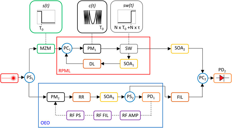
FIGURE 1. Proposed linearly chirped microwave generator (LCMW) architecture including the recirculating phase modulation loop (RPML) and the optoelectronic oscillator (OEO) (PSj: power splitter (j = 1–2); PMj: phase modulator (j = 1–2); MZM: Mach–Zehnder modulator; PCj: power combiner (j = 1–2); DL: delay line; SW: switch; RR: ring resonator; SOAi (i = 1–3): semiconductor optical amplifier; FIL: high-ER filter; PDj: photodiode (j = 1–2); RF PS: RF phase shifter; RF AMP: RF amplifier, RF FIL: RF filter).
The beam generated by an InP continuous-wave laser source, including a Bragg grating, with an output power of 20 mW, a linewidth ≤2 kHz and a relative intensity noise (RIN) of −140 dB/Hz [30], is routed in two branches by using a 3-dB power splitter (PS1) [31].
One signal is intensity modulated by an InP-based Mach–Zehnder modulator (MZM) [32], electrically driven by a square wave voltage with falling edge at time T0, that represents the target temporal duration of the chirped signal. The MZM output enters the RPML section, where the signal is phase modulated by a traveling wave InP phase modulator (PM1) with a bandwidth up to 80 GHz, Vπ = 1.5 V, and insertion loss (IL) equal to 8.5 dB [33], driven by an engineered electric parabolic waveform, amplified by a semiconductor optical amplifier (SOA1) [34] and temporally delayed by an optical delay line (DL). When the recirculating signal carries out N roundtrips within the RPML, reaching the desired chirp rate, it is routed out by using a silicon MZI switch [35], electrically driven by a square wave voltage with rise edge time at N
The other PS1 signal is phase modulated by a PM and then routed out by a PS2. The signal within the OEO is amplified by a SOA3 and then O/E transduced by a photodiode (PD1). The electrical signal is RF filtered and amplified, phase shifted [36], and then, fed back in the PM, generating the oscillating signal.
The output of OEO and RPML, properly filtered by a compact high-extinction ratio (ER) filter, and amplified by SOA2, beats at a photodiode (PD2), to generate the LCMW signal. Both PDs operate at 1.55 µm with a responsivity of 0.7 A/W, a dark current of 150 nA, a total resistance of 100 Ω, and a bandwidth >60 GHz [37].
When the MZM and SW are in “on” state, the lightwave ERP(t) at the output of the RMPL section can be expressed as follows [38]:
where E0,RP is the amplitude of ERP, f0 is the operating frequency of the light source (≈193 THz), N is the number of round-trips in the RMPL section, Vpp is the peak-to-peak voltage of the parabolic waveform, and Vπ is the half-wave voltage of the PM.
s(t) is the driven voltage of the MZM, whose output EMZM can be expressed as follows [39]:
where Vπ,MZM is the half-wave voltage of the MZM and ECW is the laser output beam. When s(t)= Vπ, the output signal is null (“off” state), while, s(t) = 0, EMZM = ECW (“on” state).
where Vπ,MZM is the half-wave voltage of the MZI-based switch. When sw(t)= Vπ,SW, the output signal is routed out of RPML (“on” state).
c(t) is the split parabolic waveform that drives the PM,
where M is the number of splitting, T0 is temporal duration of the signal, and Ω = (0,—0.5) for non-return-to-zero (NRZ) or return-to-zero (RZ) c(t) signal, and
The split parabolic waveform c(t) results by the split into M pieces, ranging from tp(i-1) to tp(i) or tn(i-1) to tn(i), of the parabolic signal and the amplitude of each piece is set to 1. When the MZM and/or SW are in “off” state, ERP(t) = 0.
Since the OEO output presents the carrier at f0 and optical sidebands at f0 ± fOEO, f0 ± 2
where E0,OEO is the amplitude of EOEO, fOEO is the oscillating frequency. In the Ka-band, it results fOEO ≈ 193.04 THz at 40 GHz.
The LCMW is generated by beating ERP (t) and EOEO(t) at the PC. By neglecting the DC component, the PD output i(t) can be expressed as follows:
where
The TBWP has been calculated after determining the instantaneous frequencies (fist,max, fist,min) from Eq. 7:
The values fist,max and fist,min represent the maximum and minimum instantaneous frequencies of the signal i(t), respectively, calculated as
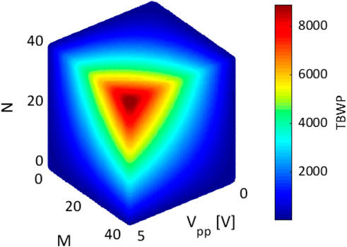
The TBWP trend vs. Vpp, M, and N is reported in Figure 2, by assuming a signal duration T0 = 15 ns. As expected, the TBWP increases as M, N, or Vpp increases, while the number of roundtrips N affects the response time of the LCMW generator. TBWP should be designed as the best compromise between the response time and the target TBWP, also in accordance with the values M and Vpp (Eq. 8). In order to keep the power consumption low, an upper Vpp value of 5 V has been considered, while the M upper limit should be set in accordance with the splitting capability of the electrical waveform generator.
To ensure the feasibility of the desired split parabolic waveform, an electronic circuit has been designed. The splitting parabolic waveform is generated by the circuit in Figure 3A, where the desired signal results from the difference between the filtered parabolic signal s1(t), with time duration T0, and an engineered step voltage signal s2(t), as described in the following.
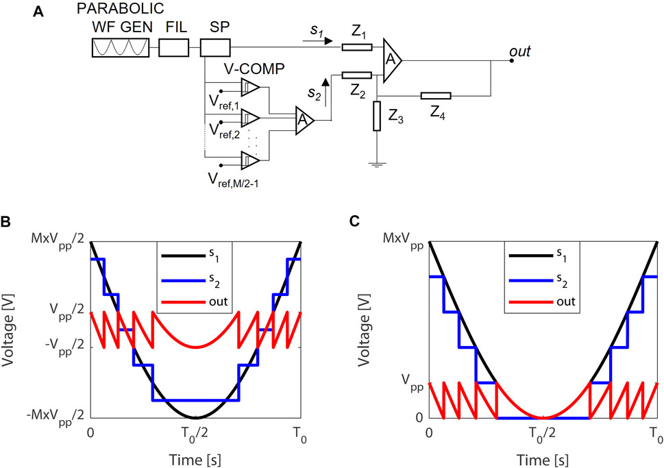
FIGURE 3. (A) Splitting parabolic signal generator; (B) non-return-to-zero (NRZ) chirped parabolic signal; (C) return-to-zero (RZ) chirped parabolic signal (PARABOLIC WF GEN: parabolic waveform generator; FIL: filter; SP: splitter; V-COMP: voltage comparator; Zi (i = 1–4): impedance).
RZ/NRZ (Figures 3B,C) parabolic signal (s1(t) in Figure 3A), generated by a parabolic waveform generator (PARABOLIC WF GEN), based on a sawtooth generator and synch pulse generator both with period T0 [40], is filtered by a single half-wave rectifier, implemented with a low threshold voltage diode (FIL) [41], and then, it is power split by a 3dB divider (SP), generating two replicas.
One replica feeds an (M/2–1)
The parabolic split signal results from the differential sum, carried out by an OPAMP, of the two electrical signals, s1(t) and s2(t). The amplitude of the resulting electrical signal can be tailored by properly engineering the impedances Z1, Z2, Z3, and Z4.
In terms of time resolution, the fall/rise edge time of voltage comparators represents the main limitation. Since the V-COMP shows a first-order behavior with 20–80% fall/rise edge time values <40 ps[42], the whole comparator input/output dynamic (0—≈ 99.9%) lasts more than 170 ps. To achieve a split piece larger than 170 ps, M could range up to 40. As example, a TBWP ≈ 600–1,200 can be calculated from Eq. 8, by considering N = 20, Vpp = 1.5 V, Vπ = 1.8 V, and M = 20–40, respectively.
Design of the LCMW Generator
Recirculating Phase Modulation Loop
In the RPML section (Figure 1), a chirped optical signal is generated. The optical signal can circulate in the loop or it can be routed to the output, depending on the state of the switch. Time delay needs to let the pulse circulating inside the loop to achieve a specific chirp rate before going out of the loop. The repetition rate of the parabolic waveform is the same as that of the resonant frequency of the RPML subsystem [24].
RPML consists of a feedback optical loop, based on a silicon power combiner (PC1), an InGaAsP/InP PM1, a 2 × 1 silicon optical switch (SW), a semiconductor optical amplifier (SOA1), and a Si3N4 optical delay line (DL), where the signal experiences multiple phase modulations increasing its chirp rate. In particular, the chirp-free signal, resulted by the MZM, driven by the step signal s(t), undergoes N-phase modulations at PM1, driven by the split parabolic signal c(t) with a peak-to-peak amplitude Vpp. The signal routes within the feedback loop up to the driven voltage sw(t) of SW is in “off” state. When sw(t) moves to the “on” state, in correspondence to the time N
When the signal routes within the RPML, it is time delayed to optically synchronize the overall system, avoiding the self-overlapping of the signal at the PM1, and to properly extract the signal when SW stands in “on” state. We have designed a delay line, that is, a Fermat spiral [45], based on Si3N4 waveguide 100 nm thick and 2.8 µm wide (propagation loss equal to 3.5 dB/m @1,550 nm [46]), with a time delay τDL ≤ 15 ns (Figure 4A), assuming the rise/fall time of the SW equal to 3.2/2.5 ns and the chirp-free signal lasting 15 ns. A minimum gap between the coils = 50 µm and R = 4 mm has been assumed to prevent cross-coupling and losses spread [47], respectively.
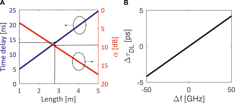
FIGURE 4. (A) Time delay τDL and propagation loss α vs. Length at f0; (B) ΔτDL = τDL (f)—τDL (f0) vs. Δf = f–f0.
As shown in Figure 4B, for the TE mode, as the total length increases, time delay τ increases at expense of worsening of the propagation losses α. With a total spiral length of 2.8 m (footprint 3.8 cm
To properly tailor the shape of the RPML output signal, N and M should be determined, to obtain a TBWP ranging from 102 to 103 and maximize the large pulse compression ratio (PCR), the RF spurious suppression ratio (RFSSR), and peak-to-sidelobe ratio (PSR).
The RFSSR is the worst power difference between the carrier and the spectrum components; the PCR is the ratio of the time length of the uncompressed transmitted pulse to the length of the compressed pulse; the PSR is the worst difference between the main autocorrelation lobe and the other components. The TBWP and the RFSRR can be estimated by the frequency spectrum of the chirped signal, while the PCR and the PSR are evaluated by the autocorrelation function of the output RPML signal.
First, since the desired TBWP is the same for both RZ and NRZ format of the signal c(t) (Eq. 8), the NRZ format has been considered in the design, in accordance with the dual-supply operation of the chosen electronic components of the LCMW generator [see Refs. (40–43)]. Another parameter to be set is the number of re-circles N. To evaluate the N impact on the LCMW performance, RPML configurations that ensure the same TBPW have been compared. Therefore, since the TBWP is directly proportional to N, the product
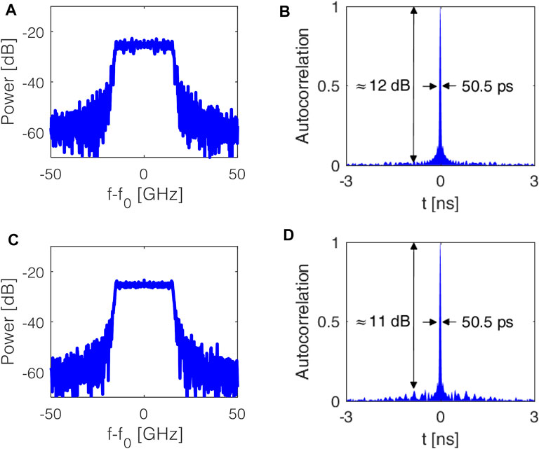
FIGURE 5. (A) RF spectrum and (B) autocorrelation function of the RPML output with Vpp = 0.8 V, N = 20, M = 20; (C) RF spectrum and (D) autocorrelation function of the RPML output with Vpp = 0.8 V, N = 10, M = 40.
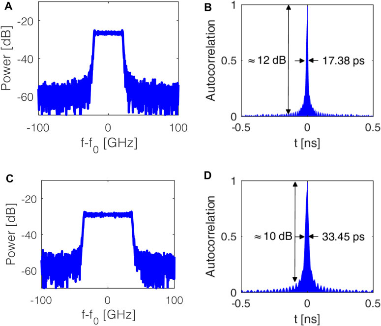
FIGURE 6. RF spectrum and autocorrelation for N = 9 (A,B), N = 18 (C,D), by assuming M = 40, Vpp = 1.1 V.
The amplitude control of the split parabolic waveform c(t) is critical for the purity of the generated signal. Since the PM output could be expressed as a combination of Bessel functions of first kind, where the amplitude of all tones strictly depends on the ratio Vpp/Vπ. Vpp also affects the RFSSR and the TBWP. To enhance the ±first-order sidebands with respect to the carrier and to higher order sidebands, a modulation index ranging from 2 to 3 represents the best compromise. Among them, the maximum RFSRR larger than 20 dB has been calculated for Vpp = 1.1 V, which corresponds to a modulation index of about 2.3.
According to Eq. 8, the TBWP increases as N or M or both increases. However, an fOEO equal to 40 GHz limits the maximum TBWP achievable by the generator. In particular, to avoid undistinguishable chirped signal at the output of the generator due to the overlapping of the signals at 0 and 80 GHz, TBWPs must be less than 1,200 (= 15 ns × 80 GHz). Therefore, we assume N = 18 as the largest possible value, by considering Vpp = 1.1 and M = 40, according to the conclusions reported in Section 3.
To rate the performance of the RPML by varying N, the RF spectra and autocorrelations have been simulated also for N = 9 (Figures 6B,C), and N = 18 (Figures 6D,E), by assuming NRZ parabolic split signal with M = 40 and Vpp = 1.1 V. As expected, the TBWP increases as N increases. In particular, TBWP ≈ 575–1,062, RFSRR ≈ 25–22 dB, PCR ≈ 448–862, and PSR ≈ 10–12 dB have been calculated for N = 9 and 18, respectively. These values are in good agreement with those obtained by Eq. 8 (= 528–1,056 for N = 9, 18, respectively). However, while TBWP increases as N increases, RFSRR worsening can be observed due to the ASE of SOA1. Finally, the tuning of N ensures the RPML and then the LCMW reconfigurability, in order to accomplish different requirements, in terms of TBWP, even in orbit.
As described in ref [38] and by comparing Figures 6B–D, the bandwidth enlargement involves the output power worsening, with an exponential trend, according to the law of conservation of the power. In the worst-case scenario, for N = 20 and M = 40, a power loss of 24 dB with respect to the chirp-free signal has been calculated. However, to compensate the losses related to the bandwidth enlargement, an SOA (SOA2 in Figure 1B) with large bandwidth, gain of 25 dB, and noise figure of 8 dB [44] has been included the RPML, with a resulting output power of −2.5 dB for N = 18.
Optoelectronic Oscillator
Another key building block to ensure the operation in the Ka band and the operating frequency reconfigurability of the LCMWG is the optoelectronic oscillator, shown in Figure 1. The operation of the optoelectronic oscillator is based on a positive feedback loop, where the optical signal in the top arm is phase modulated by PM2, filtered and delayed by the ring resonator (RR), amplified by SOA3, and, then O/E transduced by a photodiode PD1. In the bottom arm of the feedback loop, the electrical signal is amplified by RF AMP, filtered by RF FIL, phase shifted by RF PS, and then fed back to the phase modulator. The self-sustained oscillation, extracted after the PS2, starts when the SOA3 compensates the round-trip losses.
The hearth of the OEO is a high Q ring resonator that performs filtering and time-delaying functionalities. Its performance, in terms of insertion loss and Q-factor, affects the output power and phase noise. To remark the sensitive element relevance in the OEO system, two integrated ring resonators, even based on different technology platforms, have been investigated, with a Q-factor of about 106 and 109. Several configurations of high Q-factor ring resonators have been proposed in literature [48–51], demonstrating that the propagation losses strongly limited the Q-factor.
To overcome it, the investigated configuration consists of a ring resonator including a periodic structure in the resonant path (photonic crystal ring resonator, PhCRR), as investigated in Ref [47] (Figure 7A). To take advantage of very low propagation losses (in the order of dB/m @1,550 nm), the Si3N4 technology platform has been considered. The bare waveguide consists of a Si3N4 wire, with a width w = 2.8 µm and thickness t = 100 nm, placed on top of a silica layer with thickness of 15 µm [46]. A top grating, can be realized by modulating the thickness of the waveguide (tH = 100 nm and tL = 60 nm) with a width wg = w = 2.8 μm and superimposed along the whole optical path. To operate around 1,550 nm, a period Λ of 526 nm has been calculated, assuming propagation losses of 35 dB/m, which means one order of magnitude larger than the bare waveguide one [3.5 dB/m @ 1,550 nm (46)], to take into account also additional propagation losses related to the device fabrication.
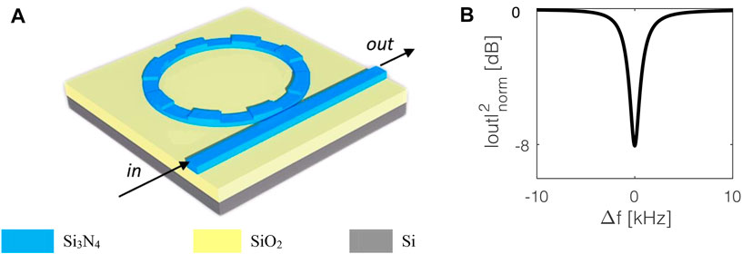
FIGURE 7. Schematic of Si3N4 RR (A) and its spectrum (B) (Δf: frequency detuning = f-fosc; |out|2norm: output power normalized with respect to the input power in).
As described in Ref [47], a Q-factor with more than three orders of magnitude, with respect to a simple ring resonator can be achieved due to the slow-light effect. For a coupler with a radius of 4 mm and bus-ring center-to-center gap g of 4.9 µm, Figure 7B shows the resonance with a Q-factor of about 2
The resonance wavelength of the ring can be tuned by exploiting the thermo-optical effect, for example, via a Peltier cell. The laser frequency f0 has to be set in accordance with the resonance frequency of the optical cavity fosc, targeting filtering at f0 + 40 GHz. For the stabilization of the laser frequency, the Pound–Drever–Hall technique can be used [52]. For simplicity, f0 = 193 THz and fosc = 193.04 THz have been considered.
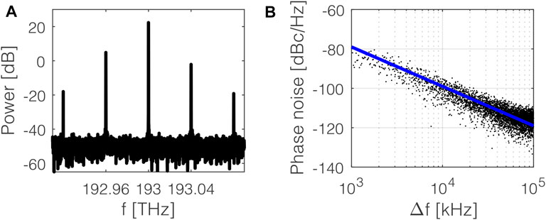
Another key building block of the OEO is the PM2, whose modulation index affects the optical response. It has been set to match the output power of the RPML (≈−2.5 dB, as in Section 3.1), and to find the best compromise between the suppression of the carrier and the excitation of 40 GHz multiples/submultiples, on which the LCMW generator output depends. A modulation index of 0.56 fulfills the aforementioned requirements, with an output power @ 193.040 THz of −2.1 dB. The output of the OEO system is depicted in Figure 8A, where the carrier at 193 THz and multiple sidebands result. The OEO shows a power difference of −20 dB and +16 dB with respect to the carrier and the second sideband, respectively. To further enhance the suppression of the 40-GHz tone with respect to the carrier and higher order sidebands, an ultrahigh extinction ratio (ER) filter has been placed in series to the OEO. The filter (FIL in Figure 1A) consists of a tunable silicon MZI, with one branch coupled to a ring resonator and the other one to three serially coupled ring resonators, with an ER = 150.55 dB and bandwidth = 0.243 nm, with a footprint of 60 µm
To rate the performance of the OEO and qualify the spectral purity of the oscillator and the short-term frequency stability, the single side-band phase noise, expressed as the ratio of the power density at an offset frequency from the carrier to the total power of the carrier, represents the main figure of merit. In particular, by extracting the signal after the PD1 and using the OEO phase noise model based on the well-known Leeson’s approach [54], a phase noise at 10 kHz offset from the carrier, within the white frequency noise section, equal to −133 dBc/Hz has been evaluated. By using a system level simulator Optisystem® associated with MATLAB®, which takes into account all noise contributions, we have calculated the dependence of the phase noise of the oscillator on Δf = f—fosc. For Δf ranging from 1 to 100 kHz, which is our region of interest [55], we have calculated the phase noise, shown in Figure 8B. As expected, the phase noise decreases as Δf increases with a slope of −20 dB/decade. For Δf = 10 kHz, the phase noise is equal to −100 dBc/Hz. The calculated phase noise value could be experimentally affected by several statistical and stochastic uncertainty effects [56]. The low value of phase noise is strictly related to the energy storage time in the oscillator circuit [57]: a time delay of 70 µs has been calculated at the resonance wavelength for the PhCRR, which represents the main novelty of the proposed OEO. Moreover, the use of an RF filter with a larger ER in the positive feedback loop of the OEO contributes to improving the phase noise. An improvement of −12 dBc/Hz has been calculated by inserting the RF filter. The mismatch between theoretically and numerically estimated phase noise is mainly due to the contribution of the RF amplifier that is not considered in Leeson’s approach [54].
Numerical Results
The LCMW signal is generated through a fast PD2 after combining the RPML and OEO output signals. The RF spectra for M = 40, N = 9 and M = 40, N = 18 are shown in Figures 9A–L, calculated by using the system-level simulator Optisystem®. For OEO based on Si3N4—PhCRR, described in Section 3.2, TBWP of 595/1,078 at 40 GHz and RFSRR of 13 dB/11 dB have been calculated for N = 9/18, respectively. The autocorrelation function of the LCMW shows an ultra-large PCR of 346/814 and PSR = 8.85/6.79 dB, for N = 9/18, respectively. The TBWPs are compliant with the predicted ones according to Eq. 8.
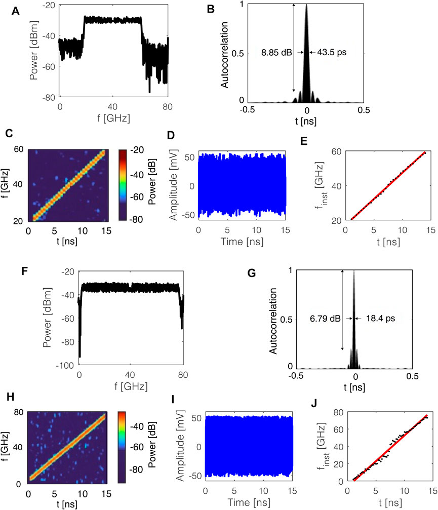
FIGURE 9. LCMW generator output spectrum, its autocorrelation function, power spectral density vs. frequency and time, time-domain waveform, and instantaneous frequency finst vs. time, for M = 40, N = 9 (A–E) and M = 40, N = 18 (F–I).
In both cases, the bandwidth of the LCMW is of the order or even larger (40 GHz, for N = 9, and 72 GHz, for N = 18) than the central frequency (40 GHz), with a consequent partial overlapping between the signal at 40 GHz and tones at 0 and 80 GHz.
Moreover, RFSRR gets worse with respect to the RPML values; it also decreases with increasing TBWP.
About the frequency sweeping linearity, as shown by Figures 9E,I, the linear fitting of the instantaneous frequencies over the time shows R2 equal to 0.9982 and 0.9855 for N = 9 and N = 18, respectively. This statistical measure demonstrates the linearity of the achieved compressed signal, which is useful for practical SAR systems.
To point out the crucial role of high-Q ring resonators in the whole system, radiation-hard InP RRs, with a radius equal to 13 mm, Q-factor of the order of 106, and ER around 6 dB [58, 59], and bared Si3N4 ring resonators, with a radius equal to 6 mm, Q-factor = 1.02
For both configurations, the achieved OEO phase noise (≈−50 dB for InP-RR and −47 dB for Si3N4—RR) involves a noisy relevant LCMW (ripple >10 dB), with an RFSSR less than 5 dB. Hence, low-phase noise OEO and high Q-factor RR, as PhCRR, are needed to enhance the LCMWG performance, in terms of TBWP, PCR, and PSR.
Furthermore, in the SAR context, the frequency tunability is very important to make the system immune to jamming, atmospheric, and mutual interference. The proposed system results are also suitable to fit the requirements of SAR adjustments and optimization after the launch. In particular, the central frequency of the chirped signal can be tuned within a frequency range of tGHz, by simply varying the input laser frequency and thermo-optically/electro-optically tuning the RR resonance frequency or both. The system reconfigurability is limited by the bandwidth of the RF filter (2 GHz). The RF filter could be omitted, at the expense of a larger phase noise (−88 dBc/Hz), or several countermeasures can be adopted, that is, by using a matrix of RF filters. Overcoming the RF filter limited tunability, the upper limit of the system reconfigurability is strictly dependent on the bandwidth of the PM (<80 GHz) and PD (<60 GHz). Therefore, according to the well-known insensitivity of the photonic devices to the operating frequency, TBWPs > 1,000 with a central frequency up to 60 GHz are envisaged. To further improve the reconfigurability, additional investigation is needed in order to make the proposed generator suitable for applications that require an ultra-large (>100 GHz) frequency tunability.
Conclusion
We have proposed a compact integrable LCMW generator, based on an RPML and OEO sections, to be used as a key building block in photonic SAR systems. The design of the whole system has been carried out aiming to achieve a TBWP ≈ 102–103, to ensure large range resolution and large RFSRR, to preserve the output signal purity. To fulfill the TBWP requirements, LCMW has been tailored by properly engineering the number of round trips N within the RPML section and the parabolic waveform, with M split pieces, which drives the PM1. To improve the RFSRR and the signal purity, a Si3N4 ring resonator with a photonic crystal has been considered, reporting a Q-factor of 2
Data Availability Statement
The original contributions presented in the study are included in the article/Supplementary Material, further inquiries can be directed to the corresponding author.
Author Contributions
GB, MA, and CC contributed to conception and design of the study. GB performed the numerical simulations. GB wrote the first draft of the manuscript. MA and CC wrote sections of the manuscript. All authors contributed to manuscript revision, read, and approved the submitted version.
Funding
The work has been supported by the Italian Ministry of Research and University in the framework of Close to the Earth project (No. ARS01_00141).
Conflict of Interest
The authors declare that the research was conducted in the absence of any commercial or financial relationships that could be construed as a potential conflict of interest.
Publisher’s Note
All claims expressed in this article are solely those of the authors and do not necessarily represent those of their affiliated organizations, or those of the publisher, the editors, and the reviewers. Any product that may be evaluated in this article, or claim that may be made by its manufacturer, is not guaranteed or endorsed by the publisher.
Acknowledgments
We greatly appreciated the fruitful suggestions provided by Eng. Giovanni Mezzina, Politecnico di Bari, on the design of the parabolic chirped generator.
References
1. Qian SE. Optical Payloads for Space Missions. Chichester, United Kingdom: John Wiley & Sons (2015).
2. Moreira A. Synthetic Aperture Radar (SAR): Principles and Applications (2013). Available from: https://earth.esa.int/documents/10174/64294 (Accessed 2021).
3. Cohen M, Larkins A, Semedo PL, Burbidge G (2017).NovaSAR-S Low Cost Spaceborne SAR Payload Design, Development and Deployment of a New Benchmark in Spaceborne Radar, In 2017 IEEE Radar Conference (RadarConf). IEEE. p. 0903–7. doi:10.1109/radar.2017.7944331
4. Pilz D, Feldle P. (2005). RF-payload of TerraSAR-X. In Proc. German Microw. Conf. (GeMiC) (pp. 140–3).
5. Imbriale WA, Boccia L. Space Antenna Handbook. Chichester, United Kingdom: John Wiley & Sons (2012).
6. Brunetti G, Conteduca D, Dell’Olio F, Ciminelli C, Armenise MN. Design of an Ultra-compact Graphene-Based Integrated Microphotonic Tunable Delay Line. Opt Express (2018) 26(4):4593–604. doi:10.1364/oe.26.004593
7. Khilo A, Spector SJ, Grein ME, Nejadmalayeri AH, Holzwarth CW, Sander MY, et al. Photonic ADC: Overcoming the Bottleneck of Electronic Jitter. Opt Express (2012) 20(4):4454–69. doi:10.1364/oe.20.004454
8. Li R, Li W, Ding M, Wen Z, Li Y, Zhou L, et al. Demonstration of a Microwave Photonic Synthetic Aperture Radar Based on Photonic-Assisted Signal Generation and Stretch Processing. Opt Express (2017) 25(13):14334–40. doi:10.1364/oe.25.014334
10. Chua MY, Koo VC. Fpga-based Chirp Generator for High Resolution Uav Sar. Pier (2009) 99:71–88. doi:10.2528/pier09100301
11. Capmany J, Novak D. Microwave Photonics Combines Two Worlds. Nat Photon (2007) 1(6):319–30. doi:10.1038/nphoton.2007.89
12. Heritage JP, Weiner AM. U.S. Patent No. 4,928,316. Washington, DC: U.S. Patent and Trademark Office (1990).
13. Li M, Wang C, Li W, Yao J. An Unbalanced Temporal Pulse-Shaping System for Chirped Microwave Waveform Generation. IEEE Trans Microwave Theor Techn. (2010) 58(11):2968–75. doi:10.1109/tmtt.2010.2079070
14. Yao J. Photonic Generation of Microwave Arbitrary Waveforms. Opt Commun (2011) 284(15):3723–36. doi:10.1016/j.optcom.2011.02.069
15. Krishnan A, Knapczyk M, de Peralta LG, Temkin H, Temkin H. Reconfigurable Direct Space-To-Time Pulse-Shaper Based on Arrayed Waveguide Grating Multiplexers and Digital Micromirrors. IEEE Photon Technol Lett (2005) 17(9):1959–61. doi:10.1109/lpt.2005.852332
16. McKinney JD, Leaird DE, Weiner AM. Millimeter-wave Arbitrary Waveform Generation with a Direct Space-To-Time Pulse Shaper. Opt Lett (2002) 27(15):1345–7. doi:10.1364/ol.27.001345
17. Wang C, Yao J. Photonic Generation of Chirped Microwave Pulses Using Superimposed Chirped Fiber Bragg Gratings. IEEE Photon Technol Lett (2008) 20(11):882–4. doi:10.1109/lpt.2008.922333
18. Zhang W, Yao J (2015).Photonic Generation of Linearly Chirped Microwave Waveform with a Large Time-Bandwidth Product Using a Silicon-Based On-Chip Spectral Shaper, In 2015 International Topical Meeting on Microwave Photonics (MWP). IEEE. p. 1–4. doi:10.1109/mwp.2015.7356718
19. Zhou P, Zhang F, Guo Q, Pan S. Linearly Chirped Microwave Waveform Generation with Large Time-Bandwidth Product by Optically Injected Semiconductor Laser. Opt Express (2016) 24(16):18460–7. doi:10.1364/oe.24.018460
20. Li J, Pu T, Zheng J, Zhang Y, Shi Y, Zhu H, et al. Photonic Generation of Linearly Chirped Microwave Waveforms Using a Monolithic Integrated Three-Section Laser. Opt Express (2018) 26(8):9676–85. doi:10.1364/oe.26.009676
21. Coutinho OL, Zhang J, Yao J. Photonic Generation of a Linearly Chirped Microwave Waveform with a Large Time-Bandwidth Product Based on Self-Heterodyne Technique. In: 2015 International Topical Meeting on Microwave Photonics (MWP). IEEE (2015). p. 1–4. doi:10.1109/mwp.2015.7356722
22. Chao Wang C, Jianping Yao J. Chirped Microwave Pulse Generation Based on Optical Spectral Shaping and Wavelength-To-Time Mapping Using a Sagnac Loop Mirror Incorporating a Chirped Fiber Bragg Grating. J Lightwave Technol (2009) 27(16):3336–41. doi:10.1109/jlt.2008.2010561
23. Li W, Kong F, Yao J. Arbitrary Microwave Waveform Generation Based on a Tunable Optoelectronic Oscillator. J Lightwave Technol (2013) 31(23):3780–6. doi:10.1109/jlt.2013.2287122
24. Li W, Yao J. Generation of Linearly Chirped Microwave Waveform with an Increased Time-Bandwidth Product Based on a Tunable Optoelectronic Oscillator and a Recirculating Phase Modulation Loop. J Lightwave Technol (2014) 32(20):3573–9. doi:10.1109/jlt.2014.2309392
25. Li Y, Dezfooliyan A, Weiner AM. Photonic Synthesis of Spread Spectrum Radio Frequency Waveforms with Arbitrarily Long Time Apertures. J Lightwave Technol (2014) 32(20):3580–7. doi:10.1109/jlt.2014.2320933
26. Zhang Y, Ye X, Guo Q, Zhang F, Pan S. Photonic Generation of Linear-Frequency-Modulated Waveforms with Improved Time-Bandwidth Product Based on Polarization Modulation. J Lightwave Technol (2017) 35(10):1821–9. doi:10.1109/jlt.2017.2651902
27. Zhang K, Zhao S, Yin Y, Lin T, Li X, Jiang W, et al. Photonic Generation and Transmission of Linearly Chirped Microwave Waveform with Increased Time-Bandwidth Product. IEEE Access (2019) 7:47461–71. doi:10.1109/access.2019.2909738
28. Van Der Tol JJGM, Oei YS, Khalique U, Nötzel R, Smit MK. InP-based Photonic Circuits: Comparison of Monolithic Integration Techniques. Prog Quan Elect (2010) 34(4):135–72. doi:10.1016/j.pquantelec.2010.02.001
29. Tran MA, Huang D, Bowers JE. Tutorial on Narrow Linewidth Tunable Semiconductor Lasers Using Si/III-V Heterogeneous Integration. APL Photon (2019) 4(11):111101. doi:10.1063/1.5124254
30.Datasheet of the RIO PLANEXTM External Cavity Laser. Available from: http://www.rio-lasers.com (Accessed 2021).
31. Zhen Sheng Z, Zhiqi Wang Z, Chao Qiu C, Le Li L, Pang A, Aimin Wu A, et al. A Compact and Low-Loss MMI Coupler Fabricated with CMOS Technology. IEEE Photon J. (2012) 4(6):2272–7. doi:10.1109/jphot.2012.2230320
32. Zhang C, Morton PA, Khurgin JB, Peters JD, Bowers JE. Highly Linear Heterogeneous-Integrated Mach-Zehnder Interferometer Modulators on Si. Opt Express (2016) 24(17):19040–7. doi:10.1364/oe.24.019040
33. Ogiso Y, Hashizume Y, Tanobe H, Nunoya N, Ida M, Miyamoto Y, et al. 80-GHz Bandwidth and 1.5-V Vπ InP-Based IQ Modulator. J Lightwave Technol (2020) 38(2):249–55. doi:10.1109/jlt.2019.2924671
34.Datasheet of Thorlabs SOA1117S – C-Band Semiconductor Optical Amplifier, Available from: https://www.thorlabs.com/thorproduct.cfm?partnumber=SOA1117S (Accessed 2021).
35. Lu L, Zhao S, Zhou L, Li D, Li Z, Wang M, et al. 16 × 16 Non-blocking Silicon Optical Switch Based on Electro-Optic Mach-Zehnder Interferometers. Opt Express (2016) 24(9):9295–307. doi:10.1364/oe.24.009295
36.Available from: http://www.millitech.com. Available from: http://www.sagemillimeter.com (Accessed 2021).
37. Shen L, Jiao Y, Yao W, Cao Z, van Engelen JP, et al. High-bandwidth Uni-Traveling Carrier Waveguide Photodetector on an InP-Membrane-On-Silicon Platform. Opt Express (2016) 24(8):8290–301. doi:10.1364/oe.24.008290
38. Brunetti G, Marocco G, Armenise MN, Ciminelli C. High Performance Chirped Microwave Generator for Space Applications. In International Conference on Space Optics-ICSO International Society for Optics and Photonics 2020 (Vol. 11852, p. 118522).
41.Datasheet of the Low Threshold Voltage Diode Texas Instruments SM74611, Available from: https://www.ti.com/lit/ds/symlink/sm74611.pdf (Accessed 2021).
42.Datasheet of Voltage Comparator Analog Devices ADCMP580. Available from: https://www.analog.com/en/products/adcmp580.html (Accessed 2021).
43.Datasheet of High-Speed OPAMP LMH3401. Available from: https://www.ti.com/product/LMH3401 (Accessed 2021).
44. Connelly MJ. Wideband Semiconductor Optical Amplifier Steady-State Numerical Model. IEEE J Quan Electron. (2001) 37(3):439–47. doi:10.1109/3.910455
45. Fermat . Lettre de Fermat à Mersenne du 3 juin 1636, dans Paul Tannery. In: Oeuvres de Fermat. T. III, S (1636). 277.
46. Bauters JF, Heck MJR, John D, Dai D, Tien M-C, Barton JS, et al. Ultra-low-loss High-Aspect-Ratio Si_3N_4 Waveguides. Opt Express (2011) 19(4):3163–74. doi:10.1364/oe.19.003163
47. Brunetti G, Dell’ Olio F, Conteduca D, Armenise MN, Ciminelli C. Comprehensive Mathematical Modelling of Ultra-high Q Grating-Assisted Ring Resonators. J Opt (2020) 22:035802. doi:10.1088/2040-8986/ab71eb
48. Luke K, Dutt A, Poitras CB, Lipson M. Overcoming Si3N4 Stress Limitations for High Quality Factor Ring Resonators. Opt Express (2013) 21:22829–22833.
49. Huang S-W, Yang J, Lim J, Zhou H, Yu M. A Low-Phase-Noise 18GHz Kerr Frequency Microcomb Phase-Locked Over 65THz. Sci Rep (2015) 5:13355.
50. Gondarenko A, Levy JS, Lipson M. High Confinement Micron-Scale Silicon Nitride High Q Ring Resonator. Opt Express (2009) 17(14):11366–11370.
51. Chen Y, Feng J, Zhou Z, Yu J, Summers CJ. Fabrication of Silicon Microring Resonator with Smooth Sidewalls. J Micro/Nanolithography, MEMS and MOEMS (2009) 8(4):043060.
52. Saleh K, Lin G, Chembo YK. Effect of Laser Coupling and Active Stabilization on the Phase Noise Performance of Optoelectronic Microwave Oscillators Based on Whispering-Gallery-Mode Resonators. IEEE Photon J (2014) 7(1):1–11.
53. Brunetti G, Sasanelli N, Armenise MN, Ciminelli C. High Performance and Tunable Optical Pump-Rejection Filter for Quantum Photonic Systems. Opt Laser Tech (2021) 139:106978. doi:10.1016/j.optlastec.2021.106978
54. Bouchier A, Saleh K, Merrer PH, Llopis O, Cibiel G. Theoretical and Experimental Study of the Phase Noise of Opto-Electronic Oscillators Based on High Quality Factor Optical Resonators. In 2010 IEEE International Frequency Control Symposium (2010) (pp. 544-548). IEEE.
55. Saleh K, Henriet R, Diallo S, Lin G, Martinenghi R, Balakireva IV. Phase Noise Performance Comparison Between Optoelectronic Oscillators Based on Optical Delay Lines and Whispering Gallery Mode Resonators. Opt Express (2014) 22:32158–32173.
56. Salzenstein P, Pavlyuchenko E. Uncertainty Evaluation on a 10.52 GHz (5 dBm) Optoelectronic Oscillator Phase Noise Performance. Micromachines (2021) 12(5):474.
57. Van der Pol B. Theory of the Amplitude of frfeE. Forced Triode Vibrations. Radio Rev (1920) 1:701–10.
58. Ciminelli C, Dell'Olio F, Armenise MN, Soares FM, Passenberg W. High Performance InP Ring Resonator for New Generation Monolithically Integrated Optical Gyroscopes. Opt Express (2013) 21(1):556–64. doi:10.1364/oe.21.000556
Keywords: synthetic aperture radar, photonic payload, optoelectronic oscillator, Linearly Chirped Microwave Waveform Generator, microwave photonics, Ka-band
Citation: Brunetti G, Armenise MN and Ciminelli C (2022) Chip-Scaled Ka-Band Photonic Linearly Chirped Microwave Waveform Generator. Front. Phys. 10:785650. doi: 10.3389/fphy.2022.785650
Received: 29 September 2021; Accepted: 14 February 2022;
Published: 12 April 2022.
Edited by:
Jifeng Liu, Dartmouth College, United StatesReviewed by:
Sanjeev Kumar Raghuwanshi, Indian Institute of Technology Dhanbad, IndiaPatrice Salzenstein, Centre National de la Recherche Scientifique (CNRS), France
Copyright © 2022 Brunetti, Armenise and Ciminelli. This is an open-access article distributed under the terms of the Creative Commons Attribution License (CC BY). The use, distribution or reproduction in other forums is permitted, provided the original author(s) and the copyright owner(s) are credited and that the original publication in this journal is cited, in accordance with accepted academic practice. No use, distribution or reproduction is permitted which does not comply with these terms.
*Correspondence: Caterina Ciminelli, Y2F0ZXJpbmEuY2ltaW5lbGxpQHBvbGliYS5pdA==
 Giuseppe Brunetti
 Mario N. Armenise
 Caterina Ciminelli