 Mingliang Long
 Huarong Deng1*
95% of researchers rate our articles as excellent or good
Learn more about the work of our research integrity team to safeguard the quality of each article we publish.
Find out more
MINI REVIEW article
Front. Phys. , 11 January 2023
Sec. Optics and Photonics
Volume 10 - 2022 | https://doi.org/10.3389/fphy.2022.1099101
This article is part of the Research Topic Miniaturized High-Power Solid-state Laser and Applications View all 23 articles
With the development of aerospace and space scientific research, satellite laser ranging (SLR) has put forward higher requirements for response speed, data density, and measurement accuracy. In coaxial common optical path laser ranging, the emitted laser and the received laser echoes pass through the same optical system. Due to the reversibility of the optical path, the laser emission, monitoring, and laser echoes’ optical path all pass through the same optical system structure, and the response speed and ranging ability of the laser ranging system have been greatly improved. Based on the SLR system of the Shanghai Astronomical Observatory (SHAO), the laser transmitting telescope with an aperture of 21 cm was used to build a polarized coaxial SLR system. It uses a picosecond pulsed laser with a pulse repetition frequency of 2 kHz and a single-pulse energy of 2 mJ. Also, a 4f system was applied to shrink the laser echo beam and filter out noise, the measurements of low-Earth orbit and long-distance high-orbit satellites were realized, and the ranging accuracy was ∼2 cm. As far as we know, this is currently the smallest aperture telescope for SLR globally, which is conducive to the miniaturization and integrated development of SLR systems.
Laser ranging accuracy can reach sub-centimeters by satellite laser ranging (SLR), and it is widely used in determining the satellite attitude, high-precision time comparison, precision orbit setting, relativity verification, and other fields [1–5]. The emission optical path of the laser in the coaxial telescope laser ranging system would be the same as the monitoring optical path for the satellites, and also, the optical system of the return laser echoes through the same as the structure. The field of view for laser beam emission is the field of view monitored by the coaxial telescope. When the satellites fall in the field of view covered by the laser beam emission, the aiming of the satellites can be quickly achieved. At the same time, since the laser beam is emitting, the monitoring optical path and laser echoes’ optical path all pass through the same optical structure, the changes in the surrounding ambient temperature have the same impact on the monitoring, emission, and laser echoes’ optical path, and it can enhance the long-term stability of the laser ranging system, which is conducive to solving the problem of automated target aiming of the laser ranging system. Compared with the separate sending and receiving SLR, it can reduce the influence of aiming off-target caused by the influence of environmental factors on the transmitting optical path and the receiving optical path caused by the circling of the transmitting laser. At the end of the 20th century, the National Aeronautics and Space Administration (NASA) used a coaxial telescope to develop a highly automated SLR system named SLR2000 [6]. A high-precision sub-millimeter-level ranging Space Geodesy Satellite Laser Ranging (SGSLR) system also uses a coaxial telescope in recent years [7].
The coaxial telescope laser ranging in lunar laser ranging (LLR) can make full use of the advantages of large-aperture telescopes to compress the divergence of the laser beam angle [8]. At present, there are only a few LLR observatories in the world, such as Apollo (an aperture of 3.5 m telescope) in America, MLRS (McDonald Laser Ranging Station, an aperture of 2.7 m telescope), Grasse (an aperture of 1.5 m telescope) in France, and MLRO (Matra Laser Observation Observatory, an aperture of 1.5 m telescope) in Italy [8, 9]. In China, the Yunnan Observatory of the Chinese Academy of Sciences has developed the LLR system based on an aperture of 1.2 m coaxial telescope, which used a mechanical rotating mirror with a pulse repetition frequency (PRF) of 10 Hz [10]. Immediately afterward, the LLR of the ‘Tian Qin Project’ of Sun Yat-sen University was up to 100 Hz [11]. At present, the rotating mirror method is generally used in the process of coaxial ranging. However, it is affected by the speed of turning the mirror, and the PRF is low and hard to increase; this makes the amount of measurement data small, and also a large-energy laser pulse output is required, which puts forward much higher requirements for the laser.
In this paper, a polarization coaxial telescope laser ranging method was applied to build a small SLR with an aperture of 21 cm telescope based on the SLR system of the Shanghai Astronomical Observatory (SHAO). With the polarization coaxial telescope, the PRF of SLR can be raised higher than that of a rotating mirror.
As the equation laser ranging [12], the average number of laser echo points D per unit time is:
where λ is the wavelength of the laser, h is the Planck constant, c is the light velocity, ηq is the quantum efficiency of a single-photon detector (SPAD), Et is the single-pulse laser energy, Ar is the effective receiving area of the telescope, AS is the reflection area of the reflector, T is atmosphere one-way transparency, Kt is the efficiency of transmitting optics, Kr is the efficiency of receiving optics, α is the attenuation factor, θt is the divergence of the laser beam, and θs is the reflector divergence angle. R is the distance from the ground station to satellite, n1 is generated by background noise, and n2 is generated by the dark noise of the SPAD itself. From the aforementioned formula, in order to increase the average number of laser echo points D, the PRF of the laser should be increased; therefore, when D is constant, increasing the PRF can reduce the single-pulse energy of the pulse laser or the effective receiving area of the system, that is, a receiving telescope with a small-aperture telescope and a low-pulse energy laser with a high PRF can be used. It is much easier to be achieved than that of a large-aperture telescope with large pulse laser energy in a low PRF.
Polarized coaxial laser ranging only requires the polarization state of the output laser, and there is no requirement for the PRF. It is possible to achieve laser ranging with a high PRF. The polarization coaxial method is shown in Figure 1, and the TFP is the thin film plate polarizer, the QWP is the quarter wave plate, and the TS is the telescope, which make a polarized coaxial generator (PCG). The linearly polarized laser passes through the TFP, and its polarization rotates 90° through the QWP to become a circularly polarized laser, and is emitted from the TS. The returned laser echo passes through the TS, QWP, at this time the circularly polarized laser changes to the vertically polarized laser, it would be reflected by the TPF, and the laser echoes would be obtained by the SPAD, therefore, laser emission and laser echoes received would be by the same telescope, and also this has nothing to do with the PRF of the laser, the high frequency coaxial laser ranging systems can be applied, which can reduce the single-pulse energy of the laser, and the small receiving area to improve the measurement accuracy and enhance the stability of the system.
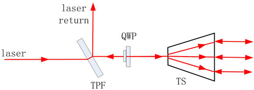
FIGURE 1. Schematic representation of a polarized coaxial generator for SLR.
The system is designed based on the SLR of the SHAO [13–15], as shown in Figure 2. Compared with the traditional high PRF of the SLR system of the SHAO [15], its laser transmitting telescope with an aperture of 21 cm was applied, the laser emission, laser reception, and satellite monitoring were all used by the aperture of 21 cm telescope system. The average power of 4 W at the wavelength of 532 nm ps laser with a divergence angle of 0.6 mrad was used, and its pulse width is about 30 ps, the PRF was 2 kHz, and beam quality was M2 = 1.2.
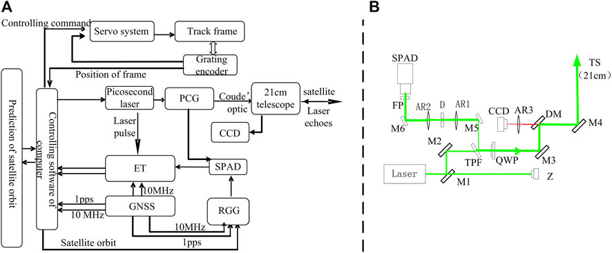
FIGURE 2. Structure (A) and optical path diagram (B) of the polarized coaxial SLR system.
The structure of polarized coaxial SLR was as shown in Figure 2A. The satellite orbit prediction parameters are downloaded to the controlling software of the computer, and the computer processes convert the satellite orbit prediction parameters, then it sends out controlling command to the servo system, which controlled the telescope mount to track the satellite with accurate feedback track from the grating encoder. The satellite would be monitored by the aperture of 21 cm polarized coaxial telescope’s monitoring charge coupled device (CCD). At this time, the laser is ignited by a ranging gate generator (RGG) through the coupé optics and the aperture of 21 cm telescope to the satellite, and also the laser pulse is processed by a discriminator, and it is sent to the event timer (ET). The ET (USB, A033 origin Latvia) would be started, and it sent the start time of laser pulses t1 to the computer, and gated pulses from RGG would be sent to SPAD (by East China Normal University, China). The laser echoes passed through the receiving system to the SPAD, and the return time t2 is obtained by the ET. In all, the RGG, computer, and ET were provided high-precision time from the GNSS′ clock. Delaying of △t0 from the polarized coaxial SLR system is considered, with the speed of light C, and the range of satellite R was as shown:
The optical path diagram of polarized coaxial SLR is shown in Figure 2B, M1, M2, M3, M5, and M6 are 45° reflective mirrors with high reflectivity mirrors at the wavelength of 532 nm green laser, DM is a 45° dichroic mirror, which is highly reflectivity at the wavelength of 532 nm and highly transmission efficiency at the other wavelengths (more than 550 nm). M4 is a 45° reflective mirror that is highly reflective in the entire visible band. The lenses AR1 and AR2 comprise a 4f system, which can reduce the laser beam to one-third. D is a small aperture, and it is located in the focal position of AR, FP is a narrow band of 4 nm filter, the SPAD is a single-photon detector, Z is the laser pulse photoelectric probe, and TS is the aperture of 21 cm telescope. The laser beam from the laser was transmitted by the M1, M2, TPF, QWP, M3, DM, M4, and TS to the satellite, and the return laser echoes were transmitted by the M4, DM, QWP, TPF, M5, AR1, D, AR2, M6, and FP to the SPAD.
The beam size of the laser echoes from the TS is larger than the receiving aperture of the SPAD. The laser echo beam needs to be compressed to reach the allowable receiving caliber of the SPAD, therefore, the lenses AR1 and AR2 are used to form a 4f system, which can reduce the laser echo beam to one-third. The laser will have part of the laser diffused and diffuse reflected on the mirrors. A small hole aperture D is inserted at the focus position of the 4f system, which can filter out most of the diffuse light into the SPAD. At the same time, the entire echo receiving part is placed in a dark box to avoid diffuse light entering the SPAD from other spaces, and also the diffuse laser from diffuse and diffuse reflection can easily enter the field of view, which would saturate interference of CDD. In this, the satellite was monitored by the CCD when the laser was output.
With the aforementioned configuration of the SLR system, an aperture of 21 cm telescope with polarized coaxial for SLR was built, the data measurement results are shown in Table 1.
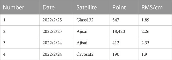
TABLE 1. Measurement results of the polarized coaxial for SLR at the PRF of 2 kHz.
As shown in Figure 3, it is the real-time measurement (Figure 3A) and measurement data processing (Figure 3B) of the laser echo detection of the far-Earth Satellite of Glonass 32, it is about 20,000 km far away, the ranging precision of root mean square is 1.89 cm. As in Figure 3B, owing to the narrow band of the 4 nm filter, the aperture of the 21 cm telescope with polarized coaxial for SLR has more noise points than that of conventional SLR at the SHAO with a narrow band of 0.15 nm filter. Also, if a narrow band of 0.15 nm filter is used in polarized coaxial for SLR, the noise points would be reduced, and the number of laser echo points would be increased.
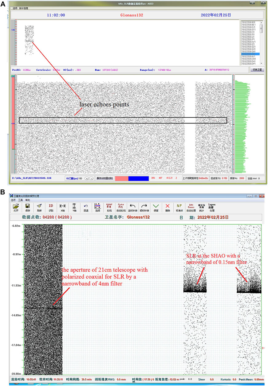
FIGURE 3. Real-time measurement (A) and data processing of the Glonass 132.
From the laser ranging equation, the requirements of pulse energy and receiving telescope size in the SLR system can be reduced by increasing the PRF of laser ranging. Through the transformation of the original ranging system of the SHAO, a PRF of 2 kHz polarized coaxial laser ranging system with an aperture of 21 cm telescope has been established. A satellite that is 20,000 km away satellite was measured with an RMS of 1.89 cm: as far as we know, this is currently the smallest aperture telescope for SLR globally for a satellite at this distance. It is demonstrated that the system could achieve small-size receiving telescopes for SLR, and it would provide high-precision laser ranging with high repetition frequency for the LLR, which can provide the basis for the miniaturization, integration, and automation development of the SLR ranging system in the future.
ML conceived the project, and ML, HD, HZ, ZW, and HL conducted the experiment. ML wrote the manuscript, and all authors contributed to discussions during its preparation. ZZ and ML supervised the project.
This work was supported by the Shanghai Science and Technology innovation action (21142201900) and the Natural Science Foundation of Shanghai (20ZR1467500).
The authors declare that the research was conducted in the absence of any commercial or financial relationships that could be construed as a potential conflict of interest.
All claims expressed in this article are solely those of the authors and do not necessarily represent those of their affiliated organizations, or those of the publisher, the editors, and the reviewers. Any product that may be evaluated in this article, or claim that may be made by its manufacturer, is not guaranteed or endorsed by the publisher.
The Supplementary Material for this article can be found online at: https://www.frontiersin.org/articles/10.3389/fphy.2022.1099101/full#supplementary-material
1. Schreiber K, Kodet J. The application of coherent local time for optical time transfer and the quantification of systematic errors in satellite laser ranging. Space Sci Rev (2018) 214:22. doi:10.1007/s11214-017-0457-2
2. Bonin J, Chambers D, Cheng M. Using satellite laser ranging to measure ice mass change in Greenland and Antarctica. The Cryosphere (2018) 12:71–9. doi:10.5194/tc-12-71-2018
3. Zhao S, Steindorfer M, Kirchner G, Zheng Y, Koid F, Wang P, et al. Attitude analysis of space debris using SLR and light curve data measured with single-photon detector. Adv Space Res (2020) 65(5):1518–27. doi:10.1016/j.asr.2019.12.005
4. Lucchesi DM, Anselmo L, Bassan M, Pardini C, Peron R, Pucacco G, et al. Testing the gravitational interaction in the field of the Earth via satellite laser ranging and the Laser Ranged Satellites Experiment (LARASE). Class Quan Gravity (2015) 32(50):155012. doi:10.1088/0264-9381/32/15/155012
5. Bai Z, Chen H, Gao X, Li S, Qi Y, Bai Z. Highly compact nanosecond laser for space debris tracking. Opt Mater (2019) 98:109470. doi:10.1016/j.optmat.2019.109470
6. Degnan JJ, Mcgarry J, Zagwodzki T, Donovan H, Patterson D, Steggerda C, et al. NASA's photon-counting SLR2000 satellite laser ranging system: Progress and applications. Maui, HI (2002).
7. Mcgarry JF, Hoffman ED, Degnan JJ, Cheek J W, Clarke C, Diegel I, et al. NASA's satellite laser ranging systems for the twenty-first century. J Geod (2019) 93(11):2249–62. Springer Berlin Heidelberg. doi:10.1007/s00190-018-1191-6
8. Battat J, Murphy TW, Adelberger EG, Gillespie B, Hoyle CD, Mcmillan RJ, et al. Corrigendum: The Apache point observatory lunar laser-ranging operation (Apollo): Two years of millimeter-precision measurements of the earth-moon range (2009, PASP, 121, 29). Publ Astron Soc Pac (2009) 121:049201. doi:10.1088/1538-3873/129/974/049201
9. Courde C, Torre JM, Samain E, Martinot-Lagarde G, Aimar M, Albanese D, et al. Lunar laser ranging in infrared at the Grasse laser station. Astron Astrophysics (2017) 602. doi:10.1051/0004-6361/201628590
10. Li Y, Fu H, Wan L, Tang R, Li Z, Zhai D, et al. Research and experiment of lunar laser ranging in Yunnan Observatories. Chin J lasers (2019) 46(1). doi:10.3788/cjl201946.0104004
11. Gao T, Zhou L, Zhang C, Zhao H, Wu X, Li M. Lunar laser ranging based on a 100 Hz repetition frequency. Appl Opt (2021) 60(36):11058. doi:10.1364/ao.442263
12. Long M, Zhang H, Yu RZ, Wu Z, Qin S, Zhang Z. Satellite laser ranging at ultra-high PRF of hundreds of kilohertz all day. Front Phys (2022) 10:1036346. doi:10.3389/fphy.2022.1036346
13. Long M, Zhang H, Meng L, Wu Z, Deng H, Qin S, et al. Satellite laser ranging at high-repetition 10 kHz in all day. J.Infrared Millim Waves (2020) 39:778∼785.
14. Long M, Zhang Z, Chen Z, Zhang H, Deng H, Wu Z, et al. A picosecond laser at 1 kHz with dual-length of regenerative amplifier for the SLR in the daytime. Optik (Stuttg) (2018) 171:833–8. doi:10.1016/j.ijleo.2018.06.143
Keywords: satellite laser ranging, polarized coaxial, high pulse repetition frequency, 4f system, picosecond laser
Citation: Long M, Deng H, Zhang H, Tan K, Lin Hs, Wu Z and Zhang Z (2023) An aperture of 21 cm telescope with polarized coaxial for satellite laser ranging. Front. Phys. 10:1099101. doi: 10.3389/fphy.2022.1099101
Received: 15 November 2022; Accepted: 30 November 2022;
Published: 11 January 2023.
Edited by:
Baitao Zhang, Shandong University, ChinaReviewed by:
Tao Zhang, Guangdong University of Technology, ChinaCopyright © 2023 Long, Deng, Zhang, Tan, Lin, Wu and Zhang. This is an open-access article distributed under the terms of the Creative Commons Attribution License (CC BY). The use, distribution or reproduction in other forums is permitted, provided the original author(s) and the copyright owner(s) are credited and that the original publication in this journal is cited, in accordance with accepted academic practice. No use, distribution or reproduction is permitted which does not comply with these terms.
*Correspondence: Huarong Deng, ZGhyQHNoYW8uYWMuY24=
Disclaimer: All claims expressed in this article are solely those of the authors and do not necessarily represent those of their affiliated organizations, or those of the publisher, the editors and the reviewers. Any product that may be evaluated in this article or claim that may be made by its manufacturer is not guaranteed or endorsed by the publisher.
Research integrity at Frontiers
Learn more about the work of our research integrity team to safeguard the quality of each article we publish.