- 1International Cultural Exchange School (ICES), Donghua University, Shanghai, China
- 2Department of Mathematics, Air University, Islamabad, Pakistan
- 3Department of Mathematics, University of Hafr Al Batin, Hafr Al Batin, Saudi Arabia
The goal of this investigation is to carry out a comprehensive analysis of hydrodynamic forces, with particular attention being paid to the power-law fluid flow across cylinders and presence gap considerations. With the assistance of the Galerkin finite element method (GFEM), the discretization of the two-dimensional system of non-linear partial differential equations was successfully completed. The research is carried out with a significant variance of the flow behavior index
1 Introduction
Non-linear fluids past over cylinders are being studied by many researchers over the years. Engineering applications are designed and later modified based on the study of hydrodynamic forces and flow configurations. Product qualities are being improved by deep and modified investigations over the years. Flow patterns and their impact are also being investigated around more than one bluff body. It is also significant to note that the arrangement/placement of obstacles in the cross-flow also plays an important role and has a practical use. Extensive work conducted on the non-Newtonian fluid flow around a single cylinder has been summarized in the previous work [1–7]. This work is aimed to increase the stage of complicatedness concerning the nature of fluid and the number of obstacles to investigate the influence of hydrodynamic forces like drag and lift while changing the gap spacing around the circular cylinders in the power-law fluid. Lesser work is available in the literature on the incompressible power-law fluid flowing over cylinders of circular nature in tandem arrangement. Regarding the positioning of the two cylinders, many investigations into non-Newtonian fluids are available [8–12].
The flow around two side-by-side circular cylinders and tandem arrangements of circular cylinders simulated the results for different Reynolds numbers. Using several modeling methodologies based on a computational fluid dynamics solver, the authors suggest that the impacts of flow patterns such as the frequency of primary vortex shedding and the frequency of the secondary cylinder interaction may be seen for flow around two rows of staggered cylinders. The behavior of Reynolds numbers and gap spacing for the flow that occurs between side-by-side cylinders can be found using a numerical study [13–16]. These researchers investigated not only the effects of different gap spacings and Reynolds numbers but also the distinct flow patterns. [17] investigated the characteristics of flow behaviors and the action of fluid forces on two cylinders with a range of staggered configurations.
A lot of computational work has been conducted to investigate drag and lift forces on obstacles in the Newtonian flow field, but analyzing the influence of non-linear viscosity functions on drag and lift is still in its embryonic stage. Because of the examination of a wake, recycling zone length, and drag and lift features, the flow of incompressible flows over cylinders of varied cross-sectional areas makes for an attractive field of study. [18] investigated numerically the effects of the drag component on a heated circular cylinder for Reynolds number
The purpose of this investigation is to compute the fluid forces based on gap aspects that are exerted over an obstacle that is submerged in a power-law fluid flow. The CFD community has not previously conducted such an analysis of forces in this domain. In view of the numerous commercial uses of flow around dual cylinders, the scope of this work has been narrowed to include only some numerical results. The results of the circular cylinder are used as a point of comparison in this section. The following is the structure of this paper: the mathematical formulation is the topic of discussion in Section 2. In Sections 3 and 4, we will investigate the influence that the computing domain has and the effect that the grid points have. In Section 5, we talk about how the spacing ratio affects the aerodynamic forces, and in Section 6, we present our findings and draw some conclusions.
2 Mathematical formulation
The continuity and momentum equations for the incompressible shear rate model are given in their compact form and are written as follows [31]:
where
where
The involved non-dimensionalized parameters are
where
3 Problem description
Consider a channel of dimensions
Let
4 Numerical approach
At a constant Reynolds number Re = 20, it is well established that viscous fluid flows are laminar, two-dimensional, and characterized by symmetrical vortices and that these flows have a relatively constant shear rate. The numerical technique has been tested to identify the convergency, accuracy, and consistency of the outputs by evaluating the present study with the literature for viscous fluids. This was conducted in order to determine whether or not the results are convergent, accurate, and reliable.
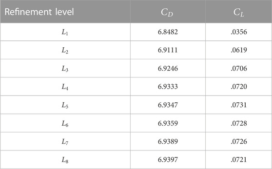
Table 1 shows the comparison between the past literature and current values for the Newtonian scenario, which is useful for code validation. The quantities of the drag coefficient for a single cylinder are maintained at a constant level of
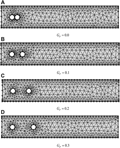
The computational coarse level grid for various gap spacings of obstacles is shown in Figure 2. For higher levels of optimization, convert one element into four narrow-size elements. The refinement mechanism is described in Figure 3.
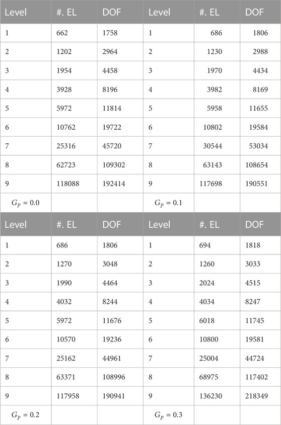
The number of elements and degrees of freedom at various stages of refinement are shown in Table 2, which was created under this method of refinement.
Table 2 contains several different depictions of the domain discretization of a channel that has a couple of cylinders arranged in a tandem configuration. These representations are facilitated at multiple levels of refinement. Based on the data that were examined on the degree of freedom at various
5 Results and discussions
(a) Impact on velocity and pressure:
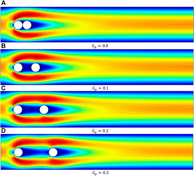
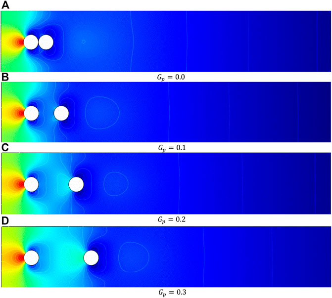
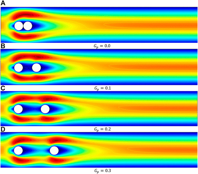
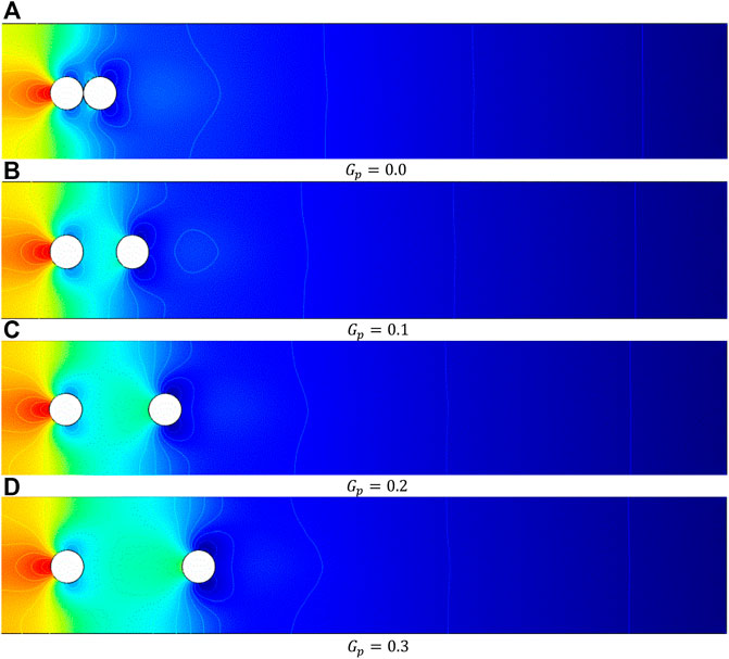
In the present work, the computations of incompressible flow have been carried out for the various quantities of the dimensionless parameters: the power law index,
Figures 8, 9 reveal the impact of
(b) Line graph behavior:
Figures 10A–E demonstrate the executed
(c) Impact of drag and lift coefficients.
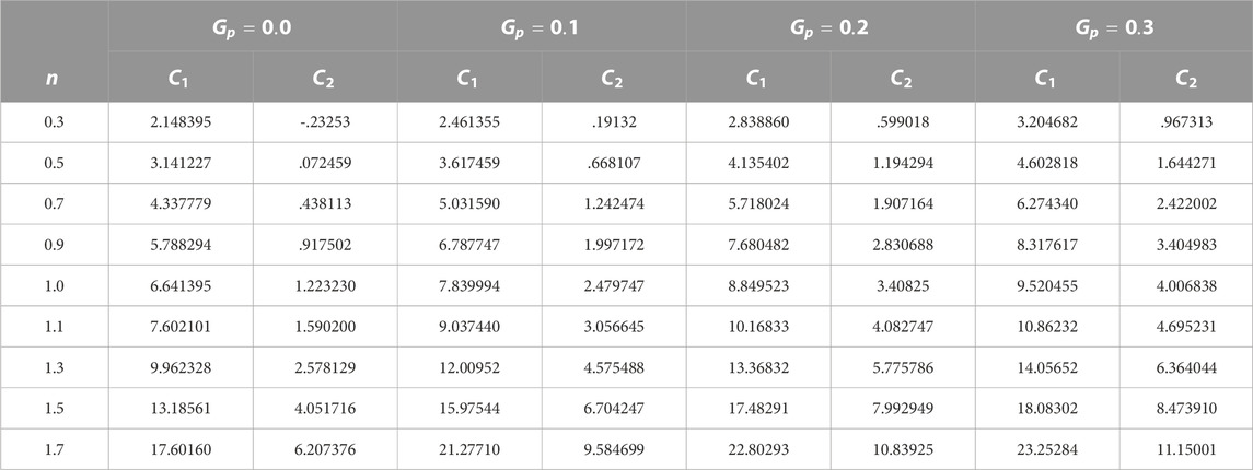
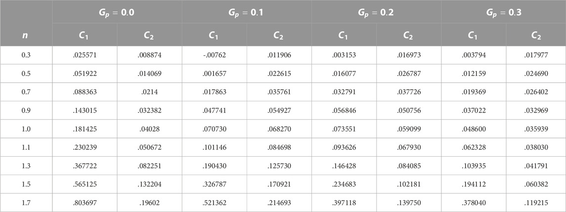
The influence of the gap ratio between the two tandem circular cylinders is at several Rein terms of force quantities, such as drag
FIGURE 10. Horizontal velocity along a vertical line at various places on the x-axis for different values of n.
6 Conclusion
We have used the GFEM to simulate how the power-law fluid flows around obstacles. It has been determined in great detail how much of an impact the flow behavior index and gap spacing have on the drag and lift coefficients of the cylinders. When calculating the drag and lift coefficients across cylinders, it has been discovered that the spacing performs a considerable role in the process. An increase in the gaps causes an increase in the amount of fluid flow that is directed toward the walls of the channel downstream of the obstacles. When there is more space between the cylinders, the pressure on the cylinder that is further downstream will be higher due to stagnation. When looking at any gap spacing, the correlation between the drag and lift coefficients is positive for the upstream cylinder, but when looking at the downstream cylinder, the correlation is negative. When it comes to tandem cylinders, the drag coefficient of both cylinders stays relatively the same even when the case involves shear-thinning.
Data availability statement
The original contributions presented in the study are included in the article/Supplementary Material; further inquiries can be directed to the corresponding authors.
Author contributions
NF and YK was responsible for funding; NF, AHM, and HS computed the results; AM and YK wrote the original draft; NF and HS wrote the review draft; AHM performed modeling; YK contributed to conceptualization; YK, AM, and AHM performed validation.
Funding
This research work was funded by institutional fund projects under no. (IFP-A-2022-2-5-24).
Acknowledgments
Therefore, authors gratefully acknowledge technical and financial support from the ministry of education and University of Hafr Al Batin, Saudi Arabia.
Conflict of interest
The authors declare that the research was conducted in the absence of any commercial or financial relationships that could be construed as a potential conflict of interest.
Publisher’s note
All claims expressed in this article are solely those of the authors and do not necessarily represent those of their affiliated organizations, or those of the publisher, the editors, and the reviewers. Any product that may be evaluated in this article, or claim that may be made by its manufacturer, is not guaranteed or endorsed by the publisher.
References
1. Bearma PW, Wadcock AJ. The interaction between a pair of circular cylinders normal to a stream. J Fluid Mech (1973) 61:499–511. doi:10.1017/s0022112073000832
2. Zdravkovich MM. REVIEW—review of flow interference between two circular cylinders in various arrangements. ASME J Fluids Eng (1977) 199:618–33. doi:10.1115/1.3448871
3. Igarashi T. Characteristics of the flow around two circular cylinders arranged in tandem: 1st report. Bull Jpn Soc Mech Eng (1981) 24:323–31. doi:10.1299/jsme1958.24.323
4. Stansby PK, Slaouti AA. A numerical study of vortex shedding from one and two circular cylinders. Aero Quart (1981) 99:48–71. doi:10.1017/s000192590000901x
5. Igarashi T. Characteristics of the flow around two circular cylinders arranged in tandem: 2nd report, unique phenomenon at small spacing. Bull Jpn Soc Mech Eng (1984) 27:2380–7. doi:10.1299/jsme1958.27.2380
6. Williamson CHK. Evolution of a single wake behind a pair of bluff bodies. J Fluid Mech (1985) 159:1–18. doi:10.1017/s002211208500307x
7. Zdravkovich MM. The effects of interference between circular cylinders in cross flow. J Fluids Structures (1987) 1:239–61. doi:10.1016/s0889-9746(87)90355-0
8. Ohya Y, Okajima A, Hayashi M. Wake interference and vortex shedding. Encycl. Fluid mech. Cheremisinoff. Houston: Gulf (1988).
9. D'Alessio SJD, Pascal JP. Steady flow of a power-law fluid past a cylinder. Acta Mechanica (1996) 117(1-4):87–100. doi:10.1007/bf01181039
10. Chhabra RP. Hydrodynamics of non-spherical particles in non-Newtonian fluids. In: NP Cheremisinoff, and PN Cheremisinoff, editors. Handbook of applied polymer processing Technology. New York: Marcel Dekker (1996). Chapter 1.
11. Zadvkovich MM. Flow around circular cylinders, Vol. 1: Fundamentals. New York: Oxford University Press (1997).
12. Chhabra RP. Heat and mass transfer in rheologically complex systems. In: D Siginer, D De Kee, and RP Chhabra, editors. Advances in the rheology and flow of non-Newtonian fluids. Amsterdan: Elsevier (1999).
13. Sumner D, Price SJ, Paidoussis MP. Flow pattern identification for two staggered circular cylinders in cross-flow. J Fluid Mech (2000) 411:263–303. doi:10.1017/s0022112099008137
14. Whitney MJ, Gregory JR. Force–velocity relationships for rigid bodies translating through unbounded shear-thinning power-law fluids. Int J non-linear Mech (2001) 36(6):947–53. doi:10.1016/s0020-7462(00)00059-7
15. Zadvkovich MM. Flow around circular cylinders, Vol. 2. New York: FundamentalsOxford University Press (2003).
16. Chhabra RP, Soares AA, Ferreira JM. Steady non–Newtonian flow past a circular cylinder: A numerical study. Acta Mechanica (2004) 172(1-2):1–16. doi:10.1007/s00707-004-0154-6
17. Alam MM, Sakamoto H, Zhou Y. Determination of flow configurations and fluid forces acting on two staggered circular cylinders of equal diameter in cross-flow. J Fluids Structures (2005) 21:363–94. doi:10.1016/j.jfluidstructs.2005.07.009
18. Soares AA, Ferreira JM, Chhabra RP. Flow and forced convection heat transfer in crossflow of non-Newtonian fluids over a circular cylinder. Ind Eng Chem Res (2005) 44(15):5815–27. doi:10.1021/ie0500669
19. P Chhabra R. Bubbles, drops and particles in non-Newtonian fluids. 2nd ed. Boca Raton, FL: CRC Press (2006).
20. Ding H, Shu C, Yeo KS, Xu D. Numerical simulation of flows around two circular cylinders by mesh-free-least-square-based finite difference methods. Int J Numer Methods Fluids (2007) 53:305–32. doi:10.1002/fld.1281
21. Mossaz S, Jay P, Magnin A. Criteria for the appearance of recirculating and non-stationary regimes behind a cylinder in a viscoplastic fluid. J Non-Newtonian Fluid Mech (2010) 165(21-22):1525–35. doi:10.1016/j.jnnfm.2010.08.001
22. Nejat A, Abdollahi V, Vahidkhah K. Lattice Boltzmann simulation of non-Newtonian flows past confined cylinders. J Non-Newtonian Fluid Mech (2011) 166(12-13):689–97. doi:10.1016/j.jnnfm.2011.03.006
23. Turkyilmazoglu M. Exact solutions concerning momentum and thermal fields induced by a long circular cylinder. Eur Phys J Plus (2021) 136(5):483–10. doi:10.1140/epjp/s13360-021-01500-1
24. Nazeer M, Ali N, Javed T, Nazir MW. Numerical analysis of the full MHD model with the Galerkin finite-element method. Eur Phys J Plus (2019) 134:204. doi:10.1140/epjp/i2019-12562-9
25. Nazeer M, Ali N, Javed T, Razzaq M. Finite element simulations for energy transfer in a lid-driven porous square container filled with micropolar fluid: Impact of thermal boundary conditions and Peclet number. Int J Hydrogen Energ (2019) 44:7656–66. doi:10.1016/j.ijhydene.2019.01.236
26. Raza R, Naz R, Abdelsalam SI. Microorganisms swimming through radiative Sutterby nanofluid over stretchable cylinder: Hydrodynamic effect. Num M Partial Dif Equs (2022) 39 (2), 975–994.
27. Faizan M, Ali F, Loganathan K, Zaib A, Reddy CA, Abdelsalam SI. Entropy analysis of sutterby nanofluid flow over a riga sheet with gyrotactic microorganisms and cattaneo–christov double diffusion. Mathematics (2022) 10:3157. doi:10.3390/math10173157
28. Abdelsalam SI, Zaher AZ. On behavioral response of ciliated cervical canal on the development of electroosmotic forces in spermatic fluid. Math Model Nat Phenom (2022) 17:27. doi:10.1051/mmnp/2022030
29. Mahmood R, Bila S, Majeed AH, Khan I, Sherif EM. A comparative analysis of flow features of Newtonian and power law material: A new configuration. J Mater Res Technol (2020) 9:1978–87. doi:10.1016/j.jmrt.2019.12.030
30. Mahmood R, Bilal S, Majeed AH, Khan I, Nisar KS. CFD analysis for characterization of non-linear power law material in a channel driven cavity with a square cylinder by measuring variation in drag and lift forces. J Mater Res Technol (2020) 9:3838–46. doi:10.1016/j.jmrt.2020.02.010
31. Mahmood R, Bilal S, Majeed AH, Khan I, Nisar KS. Assessment of pseudo-plastic and dilatant materials flow in channel driven cavity: Application of metallurgical processes. J Mater Res Technol (2020) 9:3829–37. doi:10.1016/j.jmrt.2020.02.009
32. Majeed AH, Mahmood R, Abbasi WS, Usman K. Numerical computation of MHD thermal flow of cross model over an elliptic cylinder: Reduction of forces via thickness ratio. Math Probl Eng (2021) 2021:1–13. doi:10.1155/2021/2550440
33. Bilal S, Mahmood R, Majeed AH, Khan I, Nisar KS. Finite element method visualization about heat transfer analysis of Newtonian material in triangular cavity with square cylinder. J Mater Res Technol (2020) 9(3):4904–18. doi:10.1016/j.jmrt.2020.03.010
34. Majeed AH, Jarad F, Mahmood R, Saddique I. Topological characteristics of obstacles and nonlinear rheological fluid flow in presence of insulated fins: A fluid force reduction study. Math Probl Eng (2021) 2021:2021–15. doi:10.1155/2021/9199512
35. Ahmad H, Mahmood R, Hafeez MB, Hussain Majeed A, Askar S, Shahzad H. Thermal visualization of Ostwald-de Waele liquid in wavy trapezoidal cavity: Effect of undulation and amplitude. Case Stud Therm Eng (2022) 2021.
36. Mehmood A, Mahmood R, Majeed AH, Awan FJ. Flow of the bingham-papanastasiou regularized material in a channel in the presence of obstacles: Correlation between hydrodynamic forces and spacing of obstacles. Model Simulation Eng (2021) 2021:1–14. doi:10.1155/2021/5583110
Nomenclature
n power-law index
D diameter of the obstacle
#EL number of elements
# DOF number of degrees of freedom
Keywords: GFEM, power-law fluid, hydrodynamic forces, gap spacing, cylinders
Citation: Faraz N, Majeed AH, Mehmood A, Sajad H and Khan Y (2023) Features of the power-law fluid over cylinders in a channel via gap aspects: Galerkin finite element method (GFEM)-based study. Front. Phys. 10:1081130. doi: 10.3389/fphy.2022.1081130
Received: 04 November 2022; Accepted: 28 December 2022;
Published: 16 January 2023.
Edited by:
Zhen Wang, Shandong University of Science and Technology, ChinaReviewed by:
Mustafa Turkyilmazoglu, Hacettepe University, TürkiyeSara Abdelsalam, British University in Egypt, Egypt
Copyright © 2023 Faraz, Majeed, Mehmood, Sajad and Khan. This is an open-access article distributed under the terms of the Creative Commons Attribution License (CC BY). The use, distribution or reproduction in other forums is permitted, provided the original author(s) and the copyright owner(s) are credited and that the original publication in this journal is cited, in accordance with accepted academic practice. No use, distribution or reproduction is permitted which does not comply with these terms.
*Correspondence: Afraz Hussain Majeed, YWZyYWF6Lmh1c3NhaW5Ac3R1ZGVudHMuYXUuZWR1LnBr; Y. Khan, eWFzaXJraGFuQHVoYi5lZHUuc2E=
 Naeem Faraz
 Afraz Hussain Majeed
 Asif Mehmood2
 Y. Khan

