- Science and Technology on Metrology and Calibration Laboratory, Beijing Institute of Radio Metrology and Measurement, Beijing, China
A 3-cm-long optical reference cavity for transportable miniaturized ultra-stable laser is designed and analyzed using finite element analysis (FEA). Although the tiny cavity is formed in a conventional way, in which a cylinder spacer made of ultra-low expansion (ULE) glass is optically contacted with fused-silica mirror substrates and compensation rings, the compensation rings are specially designed in order to broaden the zero-thermal-expansion temperature tuning range. In addition, the cavity is capable of being rigidly fixed by clamping both end sections of the cylinder spacer along the axis. The thermodynamic analysis shows that a larger tuning span of the zero-thermal-expansion temperature varying from −10 K to + 23 K compared to all-ULE cavity is benefited, resulting in the whole optical reference cavity could work around room temperature. Meanwhile, the statics analysis indicates the design is insensitive to extrusion force and vibration so that it owns a potential of solid performance after transportation.
1 Introduction
Ultra-stable lasers play crucial roles in diverse fields of time and frequency transfer [1], optical frequency standards [2], microwave generation [3–5], gravitational wave detection [6, 7], and fundamental physics [8, 9]. To obtain stable optical oscillations, the laser is usually locked to the resonant frequency of a passive high-finesse optical reference cavity using the Pound–Drever–Hall (PDH) technique [10]. The frequency stability of the laser is limited by the stability of the optical path length of the cavity. The performance of the stabilized laser could reach the thermal noise limit of the cavity after the temperature fluctuations and mechanical vibrations were effectively suppressed. In order to achieve extreme performance, ultra-stable lasers are usually placed in an environmentally well-controlled laboratory. However, applications such as microwave generation for radar systems [4], geodesy [11], and space physics experiments [12, 13] require an ultra-stable laser with fractional frequency instability of 10–15 level, which are characteristic of out-of-lab operations. Therefore, insensitivity to ambient fluctuations is the key to the design of a transportable optical reference cavity.
Typically, the symmetry of the cavity structure is utilized to reduce the vibration sensitivity of the cavity. To date, numerous research groups have created rigidly fixed vibration-insensitive cavities, including spherical cavities [14], cubic cavities [15, 16], cylindrical cavities [17–19], and cylindrical grooved cavities [20, 21]. These cavities have been demonstrated to have good vibration insensitivity performance, with a vibration sensitivity of 10–10/g to 10–12/g. However, they are more complex to install and require fine alignment and adjustment; otherwise, their sensitivity to vibration will deteriorate.
The need for miniaturization prevents optical reference cavities from reducing the thermal noise limit by increasing the cavity length, but optical reference cavities can be prepared by materials with lower mechanical losses. Fused silica (FS), with a much higher coefficient of thermal expansion (CTE) than ULE, is not a good choice as a spacer material but can be used as a substrate material, reducing the thermal noise limit of the cavity by a factor of 2–3 compared to ULE [22]. Due to the different CTE between the FS substrate and ULE spacer, the cavity will deform under thermal stress, resulting in a significant reduction in the zero-thermal expansion temperature of the cavity. The thermal mismatch between different materials may be compensated, though, by pasting a compensation ring. In practice, it is expected to control the zero-thermal-expansion temperature slightly above room temperature in order to reduce the difficulty of temperature control. The “sandwich” structure, in which the thermal expansion of the cavity is suppressed by applying a ULE ring to the outside of the mirror, is simple and low-cost, but has a small temperature difference tuning range of a few Kelvin, which is usually insufficient to tune the zero-thermal-expansion temperature near the desired temperature point [23]. The modified “re-entrant” structure with FS compensation rings can modify the zero-thermal-expansion temperature across a wide range though, and it is only appropriate for long cavity designs for its large volume and high sensitivity to extrusion force for miniaturized cavities [24].
In this paper, we designed a 3-cm-long miniaturized cylindrical cavity with a thermal noise limit at 10–15 level, according to the parameter of materials in Ref. [23]. The proposed thermal compensation “lantern rings” are optically contacted to the cavity to compensate the thermal mismatch between the FS substrate and ULE spacer, which are analyzed to allow for flexible tuning of the zero-thermal-expansion temperature. The tuning range of temperature difference spanning −10 K to 23 K compared to all-ULE cavity ensures that the zero-thermal-expansion temperature of the optical reference cavity can be designed at the point slightly higher than room temperature. Afterward, the fixation has been improved to facilitate installation. Section 2 analyzes the zero-thermal-expansion temperature of the proposed “lantern ring” compensation structure with the help of FEA on the Comsol Multiphysics 5.6 platform and compares it with two other conventional compensation structures. The mechanical properties of the compensated cavity subjected to extrusion force and gravity force are analyzed in Sections 3. And the thermal noise properties are discussed in Section 4.
2 Thermal mismatch compensation
As a mirror substrate, FS can reduce the thermal noise of the cavity by a factor of 2 or more, which facilitates the reference cavity to achieve better thermal noise performance when the volume is limited. The CTE of FS at room temperature is about 500 ppb/K, much larger than that of ULE (±30 ppb/K). The thermal mismatch between them causes deformation under thermal fluctuations and shifts the zero-thermal-expansion temperature away from that of the ULE and far away from room temperature. In order to regulate the zero-thermal-expansion temperature, strategies such as “sandwich” structures with the ULE ring attached to the outside of the FS mirror and a “re-entrant” structure where the mirror is embedded inside the cavity are used. In this section, we analyzed these two structures as well as the proposed “lantern ring” structure and presented simulation results.
2.1 Method of thermodynamic analysis
The material will expand or contract under thermal stress when the temperature changes. The thermal expansion can be written as [23]
For a cavity length of L and a mirror radius of R, the instantaneous CTE of the ULE spacer and FS substrate are αULE and αFS. The equivalent CTE αequ can be described as
where δ is the coupling coefficient of the mirror axial expansion. Since both ULE and FS are isotropic materials, the coupling coefficient δ is only related to the geometry of the cavity and the mechanical properties of the material. The coupling coefficient δ is a constant when a given cavity structure is in place. Therefore, we can use the coupling coefficient to calculate the zero-thermal-expansion temperature for a specific structure.
The instantaneous CTE of ULE glass around its zero-thermal-expansion temperature T0 can be approximated as quadratic temperature dependence
For a typical ULE, the quadratic coefficient b is much smaller than the linear coefficient. In the FEA, we assume that a = 2.4 × 10⁻⁹/K2 and b = 0. The CTE of FS is a constant value of 5 × 10⁻⁷/K, which is consistent with the parameters assumed in the simulation in Ref. [23], and it is experimentally demonstrated that these parameters and the model can describe the CTE variation of the composite cavity very well.
Substituting Eq. 3 into Eq. 2, the equivalent CTE of the composite cavity can be described as a linearly temperature-dependent function around the zero-thermal-expansion temperature.
Typically, the zero-thermal-expansion temperature T0 of ULE is in the range of 5°C–35°C1, ΔT is the compensation temperature difference of the composite cavity, and Tequ is the zero-thermal-expansion temperature of the composite cavity. The aim is to optimize the structure so that the zero-thermal-expansion temperature of the composite cavity is slightly above the room temperature, around 28°C. Therefore, the tuning range of ΔT is expected to cover the range from -10 K to 23 K.
The 3-cm cavity is designed as a ULE cylindrical cavity, with a central bore hole punched in the center of both the end faces and an evacuating hole punched in the perpendicular direction with an aperture of 4 mm. The mirror is selected as a standard product with a diameter of 12.7 mm and a thickness of 6 mm, optically contact to both end faces of the spacer, and the cavity is symmetrical about three orthogonal planes. The O-ring is used to apply a force parallel to the direction of the optical axis to extrude the two end faces of the cavity to fix the cavity. As the radius of the spacer is designed to be 30 mm after comprehensive consideration, there exists a certain O-ring diameter for some certain structure, where the cavity is insensitive to the applied extrusion force. However, the diameter is closely related to the structure of the composite cavity, which will be described in detail in the next section.
The thermal properties of the cavity are analyzed with the help of the Comsol Multiphysics FEA platform. Simulations are performed to calculate the equivalent zero-thermal-expansion temperature of the corresponding structure. The compensation temperature difference ΔT can be derived by Eqs 1 and 4, where ΔL is the axial displacement of the mirror center for a positive temperature step of 1 K.
Cavity lengths at multiple temperatures are computed for a certain geometric parameter, and the zero-thermal-expansion temperature is determined by fitting the length-temperature curve. The compensation temperature difference obtained this way is used to confirm the result according to Eq. 5. Due to the high symmetry of the cavity structure, we only simulate the thermodynamics of 1/8 of the cavity to improve the speed of the simulation calculation. The symmetry is ensured not to be broken during the calculation.
2.2 “Sandwich” structure
First, we analyzed the effect of the change of the zero-thermal-expansion temperature on the variation of three structural parameters of the “sandwich” structure, where the ULE ring is connected to the back side of the FS mirror and may change [23]. The geometry and thermal deformation are presented in Figures 1A,B. And the simulation results are indicated in Figures 1C,D. It can be seen that the ring thickness has a small effect on the compensation temperature difference, and the increase in the bore-aperture and the inner diameter of the ring decreases the difference. It is due to the fact that the axial constraint of the mirror is weakened when the bore-aperture or ring inner diameter is increased, allowing the mirror to expand more freely in the axial direction under thermal stress. Although the compensation temperature difference can be increased to some extent by decreasing the bore-aperture and the inner diameter of the ring, they cannot be too small; otherwise, the assumption of an open cavity will be invalid and additional diffraction loss will be incurred when the laser interacts with the cavity, thus distorting the beam. As shown in Figures 1C, D, the compensation temperature difference regulation of the sandwich structure ranges from −30 K to −20 K, far away from our desired range.
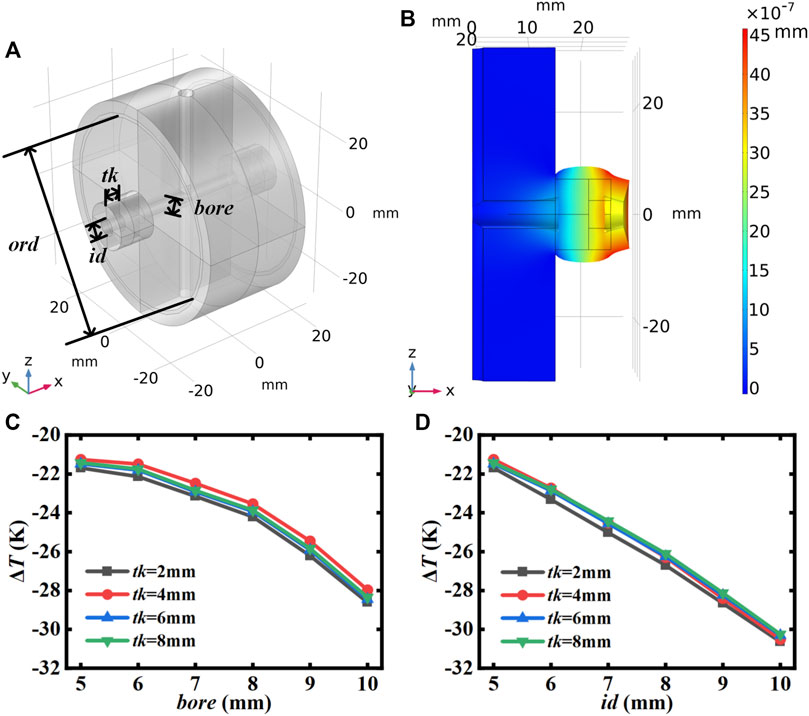
FIGURE 1. (A) 3D model of the “sandwich” structure cavity. (B) FEA simulations of the “sandwich” structure cavity deformation after a 1-K temperature step. (C,D) Compensation temperature difference for the ring inner diameter id and bore-aperture bore of 5 mm, respectively. ord, O-ring diameter; id, ring inner diameter; tk, ring thickness; bore, bore-aperture.
2.3 “Re-entrant” structure
We also analyzed a modified “re-entrant” structure in which the FS mirrors optically contact to the FS ring, followed by the FS ring optically contacted to the spacer so that the mirrors are embedded inside the spacer [24], as shown in Figures 2A,B. This allows the mirrors to expand in the opposite direction to the spacer, while the FS ring expands in the same direction, inhibiting the mirrors from expanding excessively inward to avoid excessive compensation temperature difference. As shown in Figure 2C, varying the ring thickness and ring outer diameter gives the structure a temperature difference tuning capability from 5 K to 23 K when the bore-aperture is 15 mm and the ring inner diameter is 5 mm. The reason for the trend is not monotonous, that is, the volume of the compensation ring and the contact area play different roles in the thermal expansion. The larger the volume, the more the compensation ring expands toward the outside of the cavity, making the compensation temperature difference lower. While larger contact area will restrain this effect. As shown in Figure 2D, further increasing the bore-aperture can achieve our desired temperature difference regulation capability from −10 K to 23 K. Nevertheless, this structure requires the mirrors to be embedded into the spacer, which increases the volume of the cavity, and in addition the compensation ring further increases the overall volume and increases the material consumption. Fixation is also problematic and will be described in the next section.
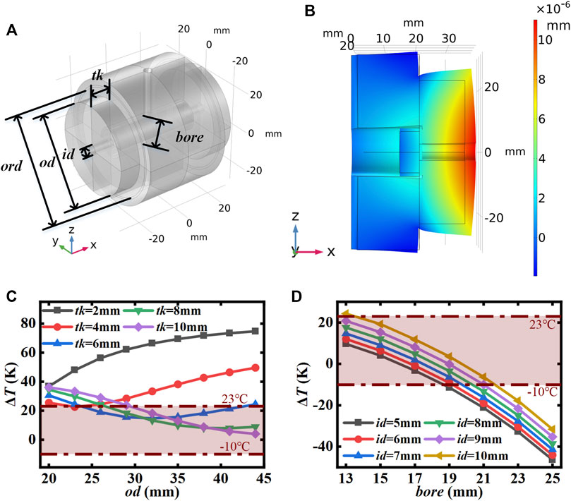
FIGURE 2. (A) 3D model of the “re-entrant” structure cavity. (B) FEA simulations of the “re-entrant” structure cavity deformation after a 1-K temperature step. (C) Compensation temperature difference for ring inner diameter of 5 mm and bore-aperture of 15 mm. (D) Compensation temperature difference for ring outer diameter of 44 mm and ring thickness of 10 mm ord, O-ring diameter; id, ring inner diameter; tk, ring thickness; bore, bore-aperture; od, ring outer diameter.
2.4 Proposed “lantern ring” structure
The proposed “lantern” structure is well-suited for the design of compensation rings for a miniaturized cavity, with two components: a cover ring and a side ring, shown in Figure 3. The bore-aperture and the inner diameter of the side ring are slightly larger than the diameter of the mirrors. First, the cover ring is optically contacted to the mirror. Then, the side ring is optically contacted to the cover ring, and finally the side ring is optically contacted to the spacer so that the mirror is in contact with the cover ring only. The cover rings are made of ULE, which inhibits expansion of the mirror with the spacer in the same direction. This structure allows the mirror to expand freely against the spacer. To avoid inward over expansion, which leads to high compensation temperature difference, the side ring is made of FS material, which can expand in the same direction as the spacer and compensate the inward over expansion of the mirror so that the tuning range meets our requirements. The FEA 3D model and thermal deformation are pictured in Figures 4A,B.
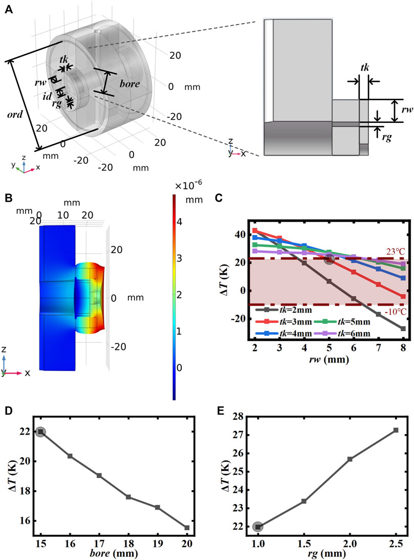
FIGURE 4. (A) 3D model and of the cross-section of the “lantern ring” structure cavity. (B) FEA simulations of the “lantern” structure cavity deformation after a 1-K temperature step. (C) Compensation temperature difference for bore-aperture of 15 mm and a side ring gap of 1 mm. (D) Compensation temperature difference for cover ring thickness of 3 mm, side ring width of 5 mm, and a side ring gap of 1 mm. (E) Compensation temperature difference for cover ring thickness of 3 mm, side ring width of 5 mm, and bore-aperture of 15 mm. The gray shadow in (C–E) shares the same structural parameters. od, ring outer diameter. ord, O-ring diameter; id, cover ring inner diameter; tk, cover ring thickness; bore, bore-aperture; rw, side ring width; rg, side ring gap.
As shown in Figure 4C, the tuning range can be made to cover our desired range from −10 K to 23 K, by adjusting the width of the side ring and the thickness of the cover ring. Larger side ring width will lead to more expansion outward the cavity, resulting in the compensation temperature difference to be lower, while the cover rings restrain this effect. The thicker the cover ring, the more solid the restraint. The compensation temperature difference can also be further adjusted by changing the bore-aperture and the side ring gap as shown in Figures 4D,E, where the gray shadow shares the same structural parameters with that in Figure 4C. The tendency can be easily seen that increasing the bore-aperture will decrease the compensation temperature difference, while increasing the side ring gap will increase it.
3 Mechanical properties
The optical reference cavity is fixed by extrusion with an O-ring at both end faces, as shown in Figure 3. The spacer and the mirror will deform under stress, that is, the change in pressure will result in an undesired change in cavity length. Fortunately, by means of FEA simulation, we can find an O-ring diameter at which the deformation of the mirror center is independent of the magnitude of the extrusion force [14, 15]. Figure 5 shows the relationship between the O-ring diameter and the relative displacement of the uncompensated cavity’s mirror for different extrusion forces. It can be seen that the pressure magnitude is proportional to the relative displacement, and the scale factor is determined by the cavity structure. There is an intersection point at the O-ring diameter of about 50.3 mm with a value of 0, meaning that the cavity is insensitive to the extrusion force of this size. For convenience of simulation, the subsequent calculation sets the extrusion force to 1 N, and the size where the relative displacement of the cavity is 0 is the extrusion force insensitive O-ring diameter.
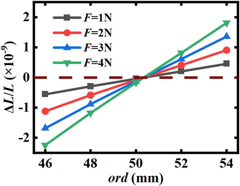
FIGURE 5. Relationship between O-ring diameter and relative axial displacement of the cavity mirror center for different extrusion forces without compensation ring.
3.1 “Re-entrant” structure
The tuning ranges of the “sandwich” structure do not meet the requirements according to Section 2.2 and are therefore not discussed here. Only the “re-entrant” structure and the “lantern ring” structure are analyzed. For the “re-entrant” structure, see Figure 2C, the compensation temperature difference ΔT > 5°C when the dimensions of the compensation ring are changed at the bore-aperture of 15 mm, and the compensation temperature difference can be reduced only by increasing the bore-aperture. Therefore, we calculated the relative axial displacement of the mirror center for the FS compensation ring size fixed at od = 44 mm and tk = 10 mm. It can be seen from Figure 6 that there is no zero-crossing point in each curve, which means that there is no extrusion pressure insensitive O-ring diameter for this structure.
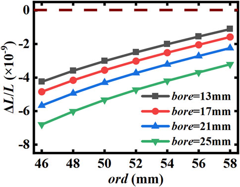
FIGURE 6. Relationship between the O-ring size and the relative axial displacement of the mirror center in the “re-entrant” structure with different bore-aperture.
This indicates that although the “re-entrant” structure can be changed to meet the desired tuning range, it cannot necessarily find a suitable installation method to make it insensitive to the extrusion pressure.
3.2 Proposed “lantern ring” structure
For the “lantern ring” structure, as shown in Figure 4C, when the cover ring thickness is 2 mm and the side ring width is varied from 3 mm to 7 mm, the compensation temperature difference can cover our requirement of −10 K to 23 K. As shown in Figure 7, the corresponding O-ring diameters can be found in all the parameter ranges covered in Figure 4C, making the cavity insensitive to the extrusion force applied. The pressure sensitivity of the O-ring is about 2 × 10⁻¹⁰/N/mm when the cover ring thickness is 2 mm. Therefore, the “lantern ring” structure is more suitable for the design of thermal compensation for miniaturized cavities.
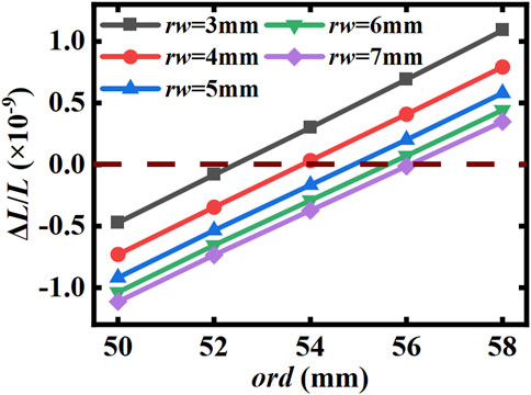
FIGURE 7. Relationship between the O-ring size and the relative axial displacement of the mirror center for different lateral ring widths with a cover ring thickness of 2 mm of the “lantern ring” structure.
In term of rigid fixation, the original design is fixed by directly extruding the two end faces of the spacer with three elastomer balls [25], which is not only difficult to align, but also the force perpendicular to the axial direction exists only by friction, which may shift under the influence of external vibration and then change its extrusion force sensitivity and vibration sensitivity, resulting in a risk of performance deterioration after long-term operation or transportation. To overcome the problem, we propose to dig small slots in the end faces of the cavity, shown in Figure 3. The FEA has determined the O-ring position so that the O-ring is plunged about 3/10 of 2 mm, the cross section’s diameter of O-ring. This can provide additional support forces in the direction perpendicular to the optical axis and facilitate the alignment during installation. As indicated by Figure 8, the presence or absence of a small slot has been found to have a negligible effect on the thermal and mechanical properties of the cavity. Moreover, in practice, the pressure pressing against the O-ring may not be evenly distributed around the circle. We increased the pressure on one semicircle by 10% and lowered the value for the other half by the same amount. The simulation shows little difference from that of pressure evenly distributed, which indicates that whether the pressure is evenly distributed or not does not affect it much.
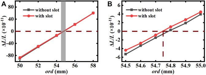
FIGURE 8. Effect of the presence or absence of a small slot on the relationship between O-ring dimensions and the relative axial deformation of the mirror center. (B) Is an enlarged view of the shaded part in (A).
3.3 Vibration mechanism
We assume that the zero-thermal-expansion temperature of ULE handy is 20°C. Using the proposed design, we can obtain ΔT = 8 K for a cover ring thickness of 2 mm and a side ring width of 4.9 mm, which means the zero-thermal-expansion temperature of the composite cavity is around 28°C. As indicated in Figure 8, the optimal size of the O-ring diameter is about 54.75 mm. In order to verify its vibration insensitivity, we applied 1 g of gravity in x, y, and z directions, and the symmetry constraint on the mid-plane except perpendicular to the direction of gravity. The translation of the slot in the x direction was allowed, while the other directions were rejected. For the gravity in the x direction, fixed constraint should be applied to one of the slot. Then, the displacement of mirrors can be calculated by static analysis to obtain the theoretical vibration sensitivity of the cavity of 2 × 10–12/g in the x direction and far more lower in the other directions. Therefore, this type of cavity is considered to have good vibration insensitivity.
4 Discussion
The thermal noise limit is calculated to be 1.3 × 10⁻¹⁵ for the cavity with 6-μm dielectric-coated FS mirrors, a radius of curvature of 1 m, and bore-aperture of 15 mm [22, 26]. It can be reduced by increasing the cavity length L [27, 28], operating at cryogenic temperature [29–32], increasing the beam radius w0 [25, 33], and using materials with low mechanical loss φ [34, 35]. Considering miniaturization and non-laboratory operation, only the latter two work. When selecting crystalline coatings with lower mechanical loss, the thermal noise limit of the optical reference cavity can be brought into the 10–16 level, namely, 5.7 × 10⁻¹⁶. As for the thermal noise induced by the compensation structure that can be negligible for the 10–15 level estimation since a finite cylinder produces lower noise than the infinite half spacer, mirror substrates with smaller radius and increased thickness will produce lower thermal noise [36]. In the condition that brown noise contributes low enough, thermo-refractive noise and thermo-optical noise should be taken into consideration for precise estimation [37, 38], and the underestimated thermal noise of the spacer induced by additional strain energy stored near the mirror should not be ignored [26, 39].
5 Conclusion
In summary, we present a design of a miniaturized transportable 3-cm-long optical reference cavity with a thermal noise limit at the 10–15 level, which is characteristic of out-of-lab applications. For the thermal mismatch between the FS substrate and the ULE spacer, the proposed design of a “lantern ring” compensation structure provides a flexibility of tuning the zero-thermal-expansion temperature of the composite cavity slightly above the room temperature, regardless of the zero-thermal-expansion temperature of the raw ULE glass within the range stated in its datasheet. The thermal noise contribution of the compensation structure can be calculated directly from the fluctuation dissipation theorem [36, 40], which is negligible for the 10–15 level. This compensation scheme is also applicable to other lengths of small cavities. Mechanical simulations are conducted to optimize the amount of the cavity and relax its installation. In addition, the designed composite cavity owns excellent vibration insensitivity according to the theoretical analysis.
Data availability statement
The original contributions presented in the study are included in the article/Supplementary Material; further inquiries can be directed to the corresponding authors.
Author contributions
All authors listed have made a substantial, direct, and intellectual contribution to the work and approved it for publication.
Funding
National Key Research and Development Program of China (No. 2021YFB3900702).
Conflict of interest
The authors declare that the research was conducted in the absence of any commercial or financial relationships that could be construed as a potential conflict of interest.
Publisher’s note
All claims expressed in this article are solely those of the authors and do not necessarily represent those of their affiliated organizations, or those of the publisher, the editors, and the reviewers. Any product that may be evaluated in this article, or claim that may be made by its manufacturer, is not guaranteed or endorsed by the publisher.
Supplementary material
The Supplementary Material for this article can be found online at: https://www.frontiersin.org/articles/10.3389/fphy.2022.1080196/full#supplementary-material
Footnotes
1https://www.corning.com/media/worldwide/csm/documents/7973%20Product%20Brochure_0919.pdf.
References
1. Foreman SM, Holman KW, Hudson DD, Jones DJ, Ye J. Remote transfer of ultrastable frequency references via fiber networks. Rev Scientific Instr (2007) 78:021101. doi:10.1063/1.2437069
2. Mcgrew WF, Zhang X, Leopardi H, Fasano RJ, Ludlow AD, Beloy K, et al. Towards the optical second: Verifying optical clocks at the SI limit. Optica (2019) 6:448. doi:10.1364/OPTICA.6.000448
3. Giunta M, Yu J, Lessing M, Fischer M, Lezius M, Xie X, et al. Compact and ultrastable photonic microwave oscillator. Opt Lett OL (2020) 45:1140–3. doi:10.1364/OL.385503
4. Fortier TM, Kirchner MS, Quinlan F, Taylor J, Bergquist JC, Rosenband T, et al. Generation of ultrastable microwaves via optical frequency division. Nat Photon (2011) 5:425–9. doi:10.1038/nphoton.2011.121
5. Xie X, Bouchand R, Nicolodi D, Giunta M, Hänsel W, Lezius M, et al. Photonic microwave signals with zeptosecond-level absolute timing noise. Nat Photon (2017) 11:44–7. doi:10.1038/nphoton.2016.215
6. Kolkowitz S, Pikovski I, Langellier N, Lukin MD, Walsworth RL, Ye J. Gravitational wave detection with optical lattice atomic clocks. Phys Rev D (2016) 94:124043. doi:10.1103/PhysRevD.94.124043
7. Abbott BP, Abbott R, Abbott TD, Abernathy MR, Acernese F, Ackley K, et al. Observation of gravitational waves from a binary black hole merger. Phys Rev Lett (2016) 116:061102. doi:10.1103/PhysRevLett.116.061102
8. Chen Q, Magoulakis E, Schiller S. High-sensitivity crossed-resonator laser apparatus for improved tests of Lorentz invariance and of space-time fluctuations. Phys Rev D (2016) 93:022003. doi:10.1103/physrevd.93.022003
9. Herrmann S, Senger A, Möhle K, Nagel M, Kovalchuk E, Peters A. Rotating optical cavity experiment testing Lorentz invariance at the 10-17 level. Phys Rev D Particles Fields (2010) 80:105011. doi:10.1103/PhysRevD.80.105011
10. Drever RWP, Hall JL, Kowalski FV, Hough J, Ford GM, Munley AJ, et al. Laser phase and frequency stabilization using an optical resonator. Appl Phys B (1983) 31:97–105. doi:10.1007/BF00702605
11. Chou CW, Hume DB, Koelemeij JCJ, Wineland DJ, Rosenband T. Frequency comparison of two high-accuracy Al+ optical clocks. Phys Rev Lett (2010) 104:070802. doi:10.1103/PhysRevLett.104.070802
12. Dionisio S, Anselmi A, Bonino L, Cesare S, Massotti L, Silvestrin P. The ‘next generation gravity mission’: Challenges and consolidation of the system concepts and technological innovations. In: 2018 SpaceOps Conference SpaceOps Conferences; 28 May - 1 June 2018; Marseille, France. American Institute of Aeronautics and Astronautics (2018). doi:10.2514/6.2018-2495
13. Luo J, Chen L-S, Duan H-Z, Gong Y-G, Hu S, Ji J, et al. TianQin: A space-borne gravitational wave detector. Class Quan Grav (2016) 33:035010. doi:10.1088/0264-9381/33/3/035010
14. Leibrandt DR, Thorpe MJ, Notcutt M, Drullinger RE, Rosenband T, Bergquist JC. Spherical reference cavities for frequency stabilization of lasers in non-laboratory environments. Opt Express, OE (2011) 19:3471–82. doi:10.1364/OE.19.003471
15. Webster S, Gill P. Force-insensitive optical cavity. Opt Lett OL (2011) 36:3572–4. doi:10.1364/OL.36.003572
16. Wiens E, Schiller S. Simulation of force-insensitive optical cavities in cubic spacers. Appl Phys B (2018) 124:140. doi:10.1007/s00340-018-7000-3
17. Tai Z, Yan L, Zhang Y, Zhang X, Guo W, Zhang S, et al. Transportable 1555-nm ultra-stable laser with sub-0.185-hz linewidth. Chin Phys Lett (2017) 34:090602. doi:10.1088/0256-307X/34/9/090602
18. Argence B, Prevost E, Lévèque T, Goff RL, Bize S, Lemonde P, et al. Prototype of an ultra-stable optical cavity for space applications. Opt Express, OE (2012) 20:25409–20. doi:10.1364/OE.20.025409
19. Świerad D, Häfner S, Vogt S, Venon B, Holleville D, Bize S, et al. Ultra-stable clock laser system development towards space applications. Sci Rep (2016) 6:33973. doi:10.1038/srep33973
20. Chen Q-F, Nevsky A, Cardace M, Schiller S, Legero T, Häfner S, et al. A compact, robust, and transportable ultra-stable laser with a fractional frequency instability of 1×10⁻¹⁵. Rev Scientific Instr (2014) 85:113107. doi:10.1063/1.4898334
21. Tao B-K, Chen Q-F. A vibration-insensitive-cavity design holds impact of higher than 100 g. Appl Phys B (2018) 124:228. doi:10.1007/s00340-018-7096-5
22. Numata K, Amy K, Jordan C. Thermal-noise limit in the frequency stabilization of lasers with rigid cavities. Phys Rev Lett (2004) 93:250602. doi:10.1103/PhysRevLett.93.250602
23. Legero T, Kessler T, Sterr U. Tuning the thermal expansion properties of optical reference cavities with fused silica mirrors. J Opt Soc Am B, JOSAB (2010) 27:914–9. doi:10.1364/JOSAB.27.000914
24. Zhang J, Luo Y, Ouyang B, Deng K, Lu Z, Luo J. Design of an optical reference cavity with low thermal noise limit and flexible thermal expansion properties. Eur Phys J D (2013) 67:46. doi:10.1140/epjd/e2013-30458-2
25. Davila-Rodriguez J, Baynes FN, Ludlow AD, Fortier TM, Leopardi H, Diddams SA, et al. Compact, thermal-noise-limited reference cavity for ultra-low-noise microwave generation. Opt Lett (2017) 42:1277. doi:10.1364/OL.42.001277
26. Kessler T, Legero T, Sterr U. Thermal noise in optical cavities revisited. J Opt Soc Am B, JOSAB (2012) 29:178–84. doi:10.1364/JOSAB.29.000178
27. Häfner S, Falke S, Grebing C, Vogt S, Legero T, Merimaa M, et al. 8 × 10^−17 fractional laser frequency instability with a long room-temperature cavity. Opt Lett (2015) 40:2112. doi:10.1364/OL.40.002112
28. Jin L, Jiang Y, Yao Y, Yu H, Zhiyi B, Ma L. Laser frequency instability of 2×10⁻¹⁶ by stabilizing to 30-cm-long Fabry-Pérot cavities at 578 nm. Opt Express (2018) 26:18699. doi:10.1364/OE.26.018699
29. Robinson JM, Oelker E, Milner WR, Zhang W, Legero T, Matei DG, et al. Crystalline optical cavity at 4K with thermal-noise-limited instability and ultralow drift. Optica, OPTICA (2019) 6:240–3. doi:10.1364/OPTICA.6.000240
30. Zhang W, Robinson JM, Sonderhouse L, Oelker E, Benko C, Hall JL, et al. Ultrastable silicon cavity in a continuously operating closed-cycle cryostat at 4 K. Phys Rev Lett (2017) 119:243601. doi:10.1103/PhysRevLett.119.243601
31. Kessler T, Hagemann C, Grebing C, Legero T, Sterr U, Riehle F, et al. A sub-40 mHz linewidth laser based on a silicon single-crystal optical cavity. Nat Photon (2012) 6:687–92. doi:10.1038/nphoton.2012.217
32. Matei DG, Legero T, Häfner S, Grebing C, Weyrich R, Zhang W, et al. 1.5 μm lasers with sub-10 mHz linewidth. Phys Rev Lett (2017) 118:263202. doi:10.1103/physrevlett.118.263202
33. Zeng XY, Ye YX, Shi XH, Wang ZY, Deng K, Zhang J, et al. Thermal noise limited higher-order mode locking of a reference cavity. Opt Lett (2018) 43:1690. doi:10.1364/OL.43.001690
34. Li L, Wang J, Bi J, Zhang T, Peng J, Zhi Y, et al. Ultra-stable 1064-nm neodymium-doped yttrium aluminum garnet lasers with 2.5×10⁻¹⁶ frequency instability. Rev Scientific Instr (2021) 92:043001. doi:10.1063/5.0025498
35. Wu L, Jiang Y, Ma C, Qi W, Yu H, Bi Z, et al. 0.26-Hz-linewidth ultrastable lasers at 1557 nm. Sci Rep (2016) 6:24969. doi:10.1038/srep24969
36. Bondu F, Hello P, Vinet J-Y. Thermal noise in mirrors of interferometric gravitational wave antennas. Phys Lett A (1998) 246:227–36. doi:10.1016/S0375-9601(98)00450-2
37. Cole GD, Zhang W, Martin MJ, Ye J, Aspelmeyer M. Tenfold reduction of Brownian noise in high-reflectivity optical coatings. Nat Photon (2013) 7:644–50. doi:10.1038/nphoton.2013.174
38. Farsi A, Siciliani de Cumis M, Marino F, Marin F. Photothermal and thermo-refractive effects in high reflectivity mirrors at room and cryogenic temperature. J Appl Phys (2012) 111:043101. doi:10.1063/1.3684626
39. Xu G, Jiao D, Chen L, Zhang L, Dong R, Liu T, et al. Thermal noise in cubic optical cavities. Photonics (2021) 8:261. doi:10.3390/photonics8070261
Keywords: optical reference cavity, finite element analysis, ultra-stable laser, zero-thermal expansion temperature, vibration insensitivity
Citation: Zhao W, Wu H, Fu Y, Ge J, Yang H and Zhang S (2023) Design of a transportable miniaturized optical reference cavity with flexibly tunable thermal expansion properties. Front. Phys. 10:1080196. doi: 10.3389/fphy.2022.1080196
Received: 26 October 2022; Accepted: 13 December 2022;
Published: 04 January 2023.
Edited by:
Shou-Gang Zhang, National Time Service Center (CAS), ChinaReviewed by:
Carlos Frajuca, Federal University of Rio Grande, BrazilLisheng Chen, Innovation Academy for Precision Measurement Science and Technology (CAS), China
Copyright © 2023 Zhao, Wu, Fu, Ge, Yang and Zhang. This is an open-access article distributed under the terms of the Creative Commons Attribution License (CC BY). The use, distribution or reproduction in other forums is permitted, provided the original author(s) and the copyright owner(s) are credited and that the original publication in this journal is cited, in accordance with accepted academic practice. No use, distribution or reproduction is permitted which does not comply with these terms.
*Correspondence: Honglei Yang, eWhscGNAMTYzLmNvbQ==; Shengkang Zhang, emhhbmdza0AxMjYuY29t
 Weinan Zhao
 Hanxu Wu
 Shengkang Zhang