 Huadong Xing1†
 Yan Gao
 Hongjun Zheng
 Hengying Xu
95% of researchers rate our articles as excellent or good
Learn more about the work of our research integrity team to safeguard the quality of each article we publish.
Find out more
ORIGINAL RESEARCH article
Front. Phys. , 10 November 2022
Sec. Optics and Photonics
Volume 10 - 2022 | https://doi.org/10.3389/fphy.2022.1056639
This article is part of the Research Topic State-of-the-Art Laser Spectroscopy and its Applications : Volume II View all 51 articles
In this study, we propose a novel three-dimensional architecture mode (de)multiplexer with degenerate modes output using a pure silica FMF ring core transmission channel, which solves the problem caused by random mode rotation and can be used in multiple-input multiple-output free (MIMO-FREE) applications such as data center application in the future. By using the pure silica FMF ring core transmission channel and larger effective refractive index difference, the performance with low loss, high extinction ratio (ER) and low crosstalk is achieved. The main channel with a few-mode fiber (FMF) ring-core structure supports the modes LP01, LP11, and LP21, and the large effective refractive index difference between each mode in the core ensures low crosstalk characteristics between the modes. Using the pure silica core channel can effectively reduce propagation attenuation and fusion loss. Our proposed MUX/DEMUX with degenerate modes output is achieved when the degenerate modes LP11a/LP11b and LP21a/LP21b are transmitted as two independent mode signals, which can be used in MIMO-FREE applications. The extinction ratios (ERs) of the degenerate modes LP11 and LP21 are kept above 31.66 dB and 24.43 dB, respectively, and the ER of mode LP01 is kept above 38.72 dB in the C band. The coupling efficiency of mode LP01 is approximately 0 dB, which is almost unchanged with the increase of the wavelength. The coupling efficiency of LP11 is higher than −3.49 dB and that of LP21 is higher than −7.24 dB in the whole C-band. At 1550 nm, the coupling efficiencies of modes LP01, LP11, and LP21 are −0.002 dB, −0.052 dB, and −0.178 dB, respectively. The coupling efficiency and ER of LP01 mode are the best, and those of the degenerate mode LP11 are always better than those of mode LP21. Our proposed MUX/DEMUX achieves low crosstalk and high ER performance and solves the problem caused by the degenerate modes rotations during transmission.
In recent years, with the growth of communication services, the traffic of the transmission system has grown exponentially, and the traditional single-mode fiber (SMF) communication capacity has converged to the Shannon limit, which cannot meet the communication demand [1]. Space division multiplexing (SDM) is a novel technology developed after successful research and application of digital coherent communication technology, which is a system that can simultaneously transmit multiple independent channel signals in a single fiber. Mode division multiplexing (MDM), which is one of the SDMs, is widely considered an effective way to improve the capacity of communication systems and networks. Especially, the weak coupling method to suppress inter-mode crosstalk has attracted much attention [2, 3, 4, 5].
Few-mode fiber (FMF) and mode-division multiplexer/demultiplexer (MUX/DEMUX) are one of the key devices for the MDM. As the transmission carrier of the MDM system, the FMF is widely focused, which can break through the nonlinear Shannon limit of SMF’s communication capacity [6, 7]. Several typical fibers reported in recent years include an elliptical-core FMF with low loss and low crosstalk for MIMO-FREE applications [8], a novel graded refractive index six-core supermode fiber [9], the polarization-maintaining elliptical ring-core fiber with four linearly polarized vector modes [10], undoped and N-doped-silica core PANDA fiber with different pulse times of radiation-induced absorption [11], low-loss four-mode-group ring-core FMFs that support only single-radial-order modes [12], low-index center and trench-assisted seven-ring-core five-mode-groups SDM fiber [13], and a 6-LP-mode ultralow-modal-crosstalk (1.49 × 10⁻³) double-ring-core FMF for weakly-coupled MDM transmission [14]. The special design of the ring core with a high refractive index increases the effective refractive index difference between modes, which can greatly suppress the mode crosstalk between modes. The pure silica core can effectively reduce the attenuation and fusion loss in the fiber, which is widely used not only in SMF [15] [16] but also in the few-mode supermode fibers [9]. The advantages of the ring-core fiber are outstanding, and its application prospects are wide, which is our preliminary consideration to study and design a mode-division (de)multiplexing device with the FMF ring-core transmission channel.
A (de)multiplexer is a more important device for optical communications; for example, a RGB wavelength (de)multiplexer based on a polycarbonate multicore polymer optical fiber is important to use wavelength division multiplexing for visible light communication system [17, 18]. Similarly, a mode-division MUX/DEMUX is a key device for mode conversion and mode-division (de)multiplexing in the MDM optical communication system. It can multiplex different channel information into one fiber for mode signal transmission or demultiplex the transmission information from one fiber into other different transmission channels. Several different MUX/DEMUXs have been proposed in order to enable the signal to be multiplexed/demultiplexed the different modes. In the literature [19], the conversion of mode LP01 to mode LP11a/LP11b in a 36-core three-mode heterogeneous few-mode multicore fiber is accomplished using a phase-plate-based mode MUX. In the 108-channel (36-cores × three-mode) mode multiplexer, the insertion loss is about 6.3–6.9 dB for mode LP01 and 7.5–9.4 dB for modes LP11a/LP11b. The mismatch between the mode field of mode LP11 in the few-mode cores and the mode field of the long-tailed quasi-LP11 mode generated through the phase plates leads to lower coupling efficiency. Also, the MUX/DEMUX device is too large due to the size of the SMF collimator. In the literature [20], the mode-division multiplexing of five spatial modes with ten channels is accomplished using photonic lanterns, but complex MIMO DSP processing is needed. In the literature [21], an all-fiber mode MUX composed of a mode-selective coupler (MSC) based on an elliptical ring-core fiber structure is used to achieve high multiplexing efficiency of seven spatial modes by employing the directional coupling method, and the mode ERs in the C-band are all above 15 dB. The large size of the photonic lantern and phase-plate-based mode division MUX makes it difficult to miniaturize and integrate the mode division multiplexing system, while the mode division MUX/DEMUX based on the directional coupling method has the advantages of all-fiber structure, high mode selectivity, high coupling efficiency, high ER, low insertion loss and mode crosstalk, simple fabrication process, low cost, etc., which can be applied to the miniaturization and integration. The directional coupling method is one of the best solutions for weak coupling technology.
For multiplexing and demultiplexing mode signals in circular-core FMFs, it is common to separately process the degenerate non-circular symmetric polarization modes (e.g., LP11a/LP11b) with the same propagation constants. Due to the effect of random rotation of the degenerate modes caused by the non-circularity of fiber fabrication and fiber twist, detecting only one of the degenerate modes will lead to power fluctuation and rapid deterioration of the bit error rate (BER) [22]. In order to solve the problems caused by rotation of the degenerate modes, two solutions can be adopted, which can be applied in the MIMO-FREE scenarios to reduce the complexity of MIMO DSP, computation, cost, etc. One solution is to design non-circular symmetric fibers to break the mode degeneracy, such as the design of the elliptical core few-mode fiber [8]. The other is to use multiplexing and demultiplexing with degenerate modes output [23, 24]. The degenerate modes in one FMF can be separately coupled with a specific degenerate modes in another FMF where the modes meet the phase-matching condition [25, 26]. In addition, by carefully choosing the spacing between fiber cores and fiber length, a direction-insensitive fiber coupler with high coupling efficiency can be designed [26, 27]. Moreover, it is reasonable to use the two degenerate modes as one signal carrier for a single-channel transmission [28], which is compatible with conventional intensity modulation and direct detection (IM/DD) systems or MIMO-FREE applications. In the literature [29], the 4-LP mode MIMO-FREE transmission with the IM/DD is achieved by cascading the degenerate modes selective coupler (DMSC) for simultaneous detection of the degenerate mode, which effectively solves the problem caused by the degenerate mode rotation, but there is a large insertion loss of −10.5 dB for the LP21 mode and a large mode crosstalk of −14.6 dB (LP11 input and LP01 output) at 1550 nm.
In this study, combining the advantages of the pure silica core, FMF ring-core, directional coupling method, and degenerate modes output, we propose a novel three-dimensional architecture mode (de)multiplexer with degenerate modes output using the pure silica FMF ring core transmission channel, which solves the problem caused by random mode rotation and can be used in MIMO-FREE applications such as data center application in the future. By using pure silica cores, low loss performance is achieved, and the intrinsic loss of each mode is better than 0.164 dB/km. By employing the ring core transmission channel and larger effective refractive index difference, the high extinction ratio (ER) and good coupling efficiency are achieved. The coupling efficiency of each mode is better than −7.24 dB in the C-band and better than −0.178 dB at 1550 nm. The effective refractive index difference of each mode in the range of 1.50 μm–1.60 μm is higher than 4.18 × 10⁻³, and the ER of each mode remains above 24.43 dB in the whole C-band and reaches above 31.60 dB at 1550 nm. We expect that the system based on our proposed (de)multiplexer can be applied in optical communication systems [30, 31, 32, 33], spectral detection and sensor systems [34, 35, 36, 37, 38] in the future, and so on.
Figure 1 shows that mode demultiplexing in two cases in the conventional mode demultiplexer occurs due to mode rotation during mode transmission. One case is (a) for the best coupling case with a rotation angle of
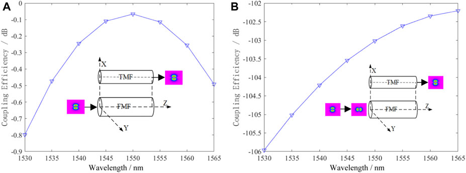
FIGURE 1. Mode rotation during the mode transmission leads to (A) the best coupling case with rotation angle of
The spatial orientation of the mode may rotate randomly in the FMF during the mode transmission due to the non-circularity of fiber fabrication, fiber twist, and other factors. Figure 1A shows all modes are transmitted along the Z-axis, and both the channels are set in the XZ plane in parallel. It can be observed that the mode coupling efficiency in the demultiplexed case is above −0.8 dB over the whole C-band, and the best value of −0.07 dB is achieved at 1550 nm. The aforementioned case is only a perfect transmission under ideal conditions. Although the mode demultiplexer remains unchanged, the demultiplexing transmission result is the worst, as shown in Figure 1B, when the mode direction is rotated by
Figure 2 shows the (de)multiplexing principle with the directional coupling method. Figure 2A is an illustration of the conventional MUX/DEMUX, and Figure 2B is that of our proposed MUX/DEMUX. Figure 2A shows the spatial orientation of the non-circular symmetric mode LPlm (l ≠ 0) in the FMF core is at an α angle to the horizontal line connecting the core axes [39]. It is proved that the coupling coefficient between the LP11 in the FMF core and the fundamental mode in a single-mode fiber has cos (lα) dependence on the spatial orientation of the non-circular symmetric mode. The antisymmetry of the product of the electronic fields around the horizontal axis gives zero coupling coefficient for α = π/2l, even though perfect phase matching is satisfied. No power of the higher-order mode can be coupled to the fundamental mode for α = π/2l.
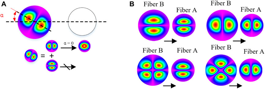
FIGURE 2. (De)multiplexing principle with the directional coupling method. (A) Illustration of conventional MUX/DEMUX. (B) Illustration of our proposed MUX/DEMUX.
If the degenerate modes are simultaneously multiplexed/demultiplexed from fiber B into fiber A, then fiber A supports at least two spatial degrees of freedom. So, fiber A must be a FMF. However, the fiber B should not be the same as fiber A because all modes in the same fiber will satisfy the phase-matching condition at the same time, where the mode selectivity is lost. So, the best solution is that fiber A is designed as a TMF. As shown in Figure 2B, mode LPlma in the FMF B is coupled to mode LP11a in the TMF A, and mode LPlmb in the FMF B is coupled to mode LP11b in the TMF A at the same time, showing that mode multiplexing/demultiplexing with the degenerate modes output is achieved. The coupled-mode equations are as follows [29]:
where
Assuming no excitation power in the initial TMF A, the normalized power transfer functions for mode LP11a (LP11b) of the TMF A and mode LPlma (LPlmb) of the FMF B are obtained, respectively.
The power of modes LPlma and LPlmb in the FMF B can be fully coupled to modes LP11a and LP11b in the TMF A when Eqs 9 and 10 are satisfied. L is the coupling length, p, q∈z. Eqs 9 and 10 show the phase-matching between the LPlm mode in the FMF and the LP11 mode in the TMF, which ensures maximum power transfer and mode selectivity. It is to be noted that the low-order LP mode of the FMF cannot match the LP01 mode of the TMF to avoid additional mode crosstalk. Eqs 11 and 12 ensure the simultaneous (de)multiplexing with the degenerate modes output. Generally, the phase-matching condition can be realized by choosing proper fibers or pre-tapering one fiber during the fabrication. Eqs 11 and 12 can be satisfied by tuning the core-to-core spacing and the coupling distance. That is to say, the (de)multiplexing principle of the degenerate modes output is based on phase-matching and transverse modal spatial distribution matching. The phase-matching is consistent with Eqs 9 and 10, which is the same as propagation constant matching and refractive index matching. The transverse modal spatial distribution matching consists of Eqs 11 and 12, which ensures simultaneous (de)multiplexing with the degenerate modes output.
The aforementioned results can also be verified using the beam-propagation method (BPM). We discuss the optimization of relevant parameters using the BPM. Figure 3 shows that the coupling efficiencies of the output modes LP11a/LP11b in the TMF1 at 1550 nm vary with the increase of the length of the fiber core channel in the case of the input modes LP11a/LP11b in the input FMF. The maximum power transfer and mode selectivity of the degenerate modes LP11a/LP11b are realized for phase-matching. The maximum power of the mode LP11a is well-consistent with that of LP11b by tuning the core-to-core spacing and the coupling distance, which ensures simultaneous (de)multiplexing with the output of the two degenerate modes. That is to say, Eqs 11 and 12 are satisfied by tuning the core-to-core spacing and the coupling distance, and the (de)multiplexing with the two degenerate modes output is achieved. In order to be convenient for the MUX/DEMUX fabrication, the maximum power of the mode LP11a can be basically consistent with that of LP11b by tuning the core-to-core spacing and the coupling distance. From Figure 3, the transmission channel length of the MUX/DEMUX can be L1 = 12.52 mm because the normalized coupling powers of the degenerate modes can reach the maximum in this case.
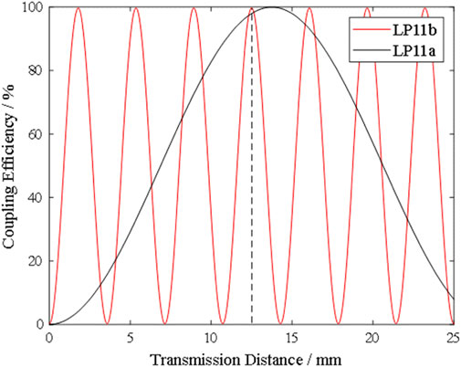
FIGURE 3. Variation of coupling efficiency of the output modes LP11a/LP11b in the TMF1 in the case of the input modes LP11a/LP11b in the FMF.
Figure 4 shows that the coupling efficiencies of the output modes LP11a/LP11b in the TMF2 at 1550 nm vary with the increase in the length of the fiber core channel in the case of the input modes LP21a/LP21b in the input FMF. From Figure 3, the transmission channel length of the MUX/DEMUX can be L2 = 8.95 mm because the normalized coupling powers of the degenerate modes can reach the maximum in this case.
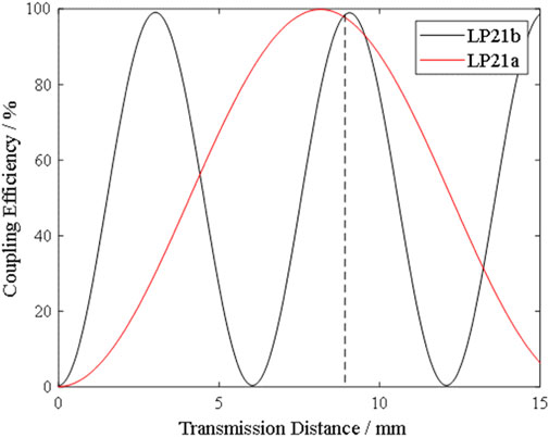
FIGURE 4. Variation of coupling efficiency of the output modes LP11a/LP11b in the TMF2 in the case of the input modes LP21a/LP21b in the FMF.
The loss is one of the most important impairments that determine the capacity of fiber optic communication systems. The minimum loss of SMF is limited by two mechanisms, namely, Rayleigh scattering and infrared absorption loss.
Intrinsic loss of arbitrary transmission modes in optical fibers [40]
where
When the fiber is uniformly doped, the Rayleigh scattering loss can be expressed as
where
where
The Rayleigh scattering coefficient of pure silica is
The infrared absorption loss of each mode supported by the FMF is the same as that of the fundamental mode in the SMF [40]:
where B and b are constants that depend only weakly on the doping level and λ is the wavelength. The parameters for pure silica cores and doped types of fibers are
The coupling efficiency of the mode
where
The ER of the mode is [27]
where
Since the MUX/DEMUX can simultaneously multiplex/demultiplex two degenerate modes, its coupling efficiency and ER should be related to both the degenerate modes. Therefore, we normalize the experimental data of both the degenerate modes to characterize the MUX/DEMUX.
Three-dimensional (3D) mode-division MUX/DEMUX has the advantages of small size and easy integration compared to the traditional two-dimensional cascaded coupled mode-division MUX/DEMUX. We propose a mode-division MUX/DEMUX with degenerate modes output, as shown in Figure 5. As can be observed from Figure 5, our proposed MUX/DEMUX consists of three different FMF core transmission channels. We demonstrate the demultiplexing process of our proposed MUX/DEMUX as an example. The FMF ring-core is the main transmission channel of the MUX/DEMUX, supporting three modes, namely, LP01, LP11, and LP21. The FMF is placed on the z-axis, where the axis of the FMF coincides with the z-axis. Two different two-mode fiber (TMF) cores, namely, TMF1 and TMF2, which are made of the conventional single core, are placed in the x and y axes, respectively. The TMF1 and TMF2 axes are parallel to the FMF axis from the x and y axes, respectively. The modes LP01, LP11, and LP21 are incident from the left end of the FMF core, which transmit and demultiplex along the z direction. We set that the mode LP01 is transmitted along the main transmission channel FMF from the left end to the right end. According to the coupling mode theory, the degenerate modes LP11a/LP11b are incident from the left end of the FMF, directly coupled to the modes LP11a/LP11b in the TMF1, respectively. That is to say, the demultiplexing of the modes LP11a/LP11b is achieved with the degenerate modes output. The degenerate modes LP21a/LP21b are incident from the left end of FMF, transformed and coupled into the modes LP11b/LP11a in TMF2, respectively. That is to say, the demultiplexing of the modes LP21a/LP21b is achieved with the degenerate modes output. So, the demultiplexing of three modes LP01, LP11, and LP21 is achieved from the main transmission channel FMF. The multiplexing process is inverse. If the degenerate modes LP01, LP11, and LP11 are incident from the left end of FMF, TMF1, and TMF2, respectively, the multiplexing with the degenerate modes output is achieved in the FMF along the z-direction.
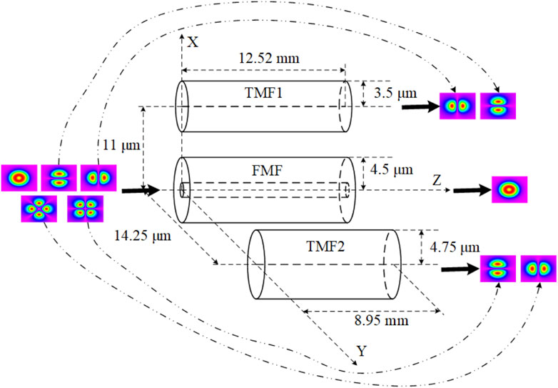
FIGURE 5. 3D view of our proposed MUX/DEMUX.
According to the (de)multiplexing principle in Section 2.2, we optimize the relevant parameters of our proposed MUX/DEMUX. The core diameter of TMF1 is 7 μm, the refractive index of the core is 1.4490, the TMF1 cladding is carried out with a F-doped silica of 1.4252, the axis distance between the two cores is 11 μm, and the transmission channel length of the TMF1 is L1 = 12.52 mm. The core diameter of TMF2 is 9.5 μm, the refractive index of the core is 1.4346, the TMF2 cladding and FMF cladding use the F-doped silica of 1.4252, the axis distance between the two cores is 14.25 μm, and the transmission channel length of the L2 = 8.95 mm. The FMF is the main transmission channel with ring core, where the part with 2 μm ≤ d ≤ 9 μm (the diameter d) is the ring core. The ring core is made of pure silica with a refractive index of
The FMF core is an important transmission carrier to realize mode-division multiplexing technology. We propose a FMF ring-core with the step index distribution as the main transmission channel. This FMF ring-core supports three modes, LP01, LP11 (LP11b/LP11a), and LP21 (LP21a/LP21b). Figure 6 shows the refractive index distribution of the FMF ring-core, where plot (a) represents the refractive index distribution along the radial direction of the FMF ring-core and plot (b) represents the contour distribution along the cross-section of the FMF ring-core. The part with the diameter d < 2 μm is the inner cladding layer, which is made of F-doped silica with the refractive index
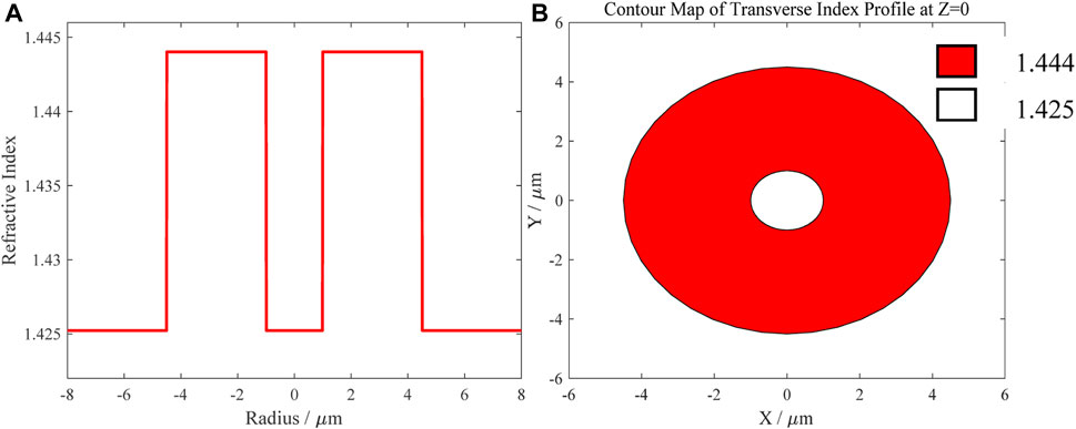
FIGURE 6. Refractive index distribution of FMF ring-core. (A) Refractive index distribution along the radial direction of the FMF ring-core. (B) Contour map of refractive index distribution along the cross-section of the FMF ring-core.
Figure 7 shows the variations of the effective refractive index difference of the three modes, namely, LP01, LP11, and LP21, in the FMF ring-core in the wavelength range of 1500 nm–1600 nm, which are represented by the curves with the circles, asterisks, and triangles, respectively. Figure 7 shows that in the wavelength range of 1500 nm–1600 nm, the index difference between the mode LP01 and LP11
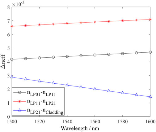
FIGURE 7. Effective refractive index difference between the modes in the FMF. The curve marked with the circles indicates the index difference between modes LP01 and LP11
Using the method in the literature [40], we obtain the intrinsic loss of the main transmission channel of our MUX/DEMUX as follows. The reasons that the analysis of intrinsic loss is added in this study are as follows, first, our proposed (de)multiplexer is designed for the special transmission fiber, which is the same as our pure silica FMF ring-core transmission channel. The fusion loss between our (de)multiplexer and the transmission FMF is low due to their same transmission channel. Second, we can generally consider the (de)multiplexer and transmission FMF as a system. So, the intrinsic loss is suitable to be considered because the FMF length of the system is usually very long.
The results of the intrinsic losses of the main transmission channel are shown in Figure 8. Plot (a) represents the intrinsic loss of pure silica FMF ring-core in our proposed MUX/DEMUX, plot (b) shows the intrinsic loss of the equivalent FMF with GeO2-doped ring-core, and plot (c) indicates the intrinsic loss of the equivalent FMF with the conventional GeO2-doped single core. The inset shows the variation of the refractive index of the transmission channel with the radius. From Figure 8A, the intrinsic losses of all modes of the FMF ring-core transmission channel reach low values in the C-band. When the wavelength is 1540 nm, the intrinsic losses of the modes LP01, LP11, and LP21 are 0.152 dB/km, 0.153 dB/km, and 0.164 dB/km, respectively. At 1550 nm, the transmission loss of all three spatial modes is less than 0.164 dB/km, which is better than the 0.3 dB/km in the literature [41]. When the wavelength is less than 1540 nm, the intrinsic losses of the three modes increase with the decrease of the wavelength, mainly because the Rayleigh scattering losses become larger with the decrease of the wavelength. When the wavelength is larger than 1540 nm, the intrinsic losses of the three modes increase with the increase of the wavelength, mainly because the infrared losses become larger with the increase of the wavelength. Therefore, the optical loss is effectively reduced by using pure silica ring-core, and the crosstalk can be effectively reduced by using a large effective refractive index difference between the modes. This achieves the operation of low-loss and low-crosstalk, which further improves the performance of the transmission channel. Figure 8B shows that the intrinsic losses of all three modes in the FMF with GeO2-doped ring-core are larger than those of our proposed FMF with the pure silica ring-core. The lowest intrinsic losses of all three modes are achieved at 1560 nm with the lowest values of 0.205 dB/km, 0.204 dB/km, and 0.193 dB/km, respectively. The intrinsic losses of the three modes vary with the wavelength, which is similar to that in Figure 8A. From Figure 8C, it can be observed that the intrinsic losses of the three modes of the conventional FMF with GeO2-doped single core are greater than those of our proposed FMF ring core, where the variation of intrinsic losses with the wavelength is also similar to that in Figure 8A. The lowest intrinsic losses of the three modes are achieved at 1560 nm with 0.210 dB/km, 0.205 dB/km, and 0.193 dB/km, respectively, which are 38%, 34%, and 18% larger than those of the three modes in our proposed FMF ring core in Figure 8A.
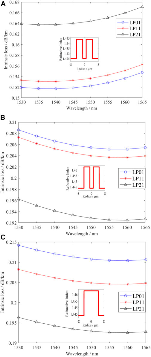
FIGURE 8. Intrinsic loss of the main transmission channel. (A) Intrinsic loss of pure silica FMF ring-core in our MUX/DEMUX. (B) Intrinsic loss of the equivalent FMF with GeO2-doped ring-core. (C) Intrinsic loss of the equivalent FMF with the conventional GeO2-doped single core.
Figure 8 shows that the variations of the intrinsic losses with the wavelength are similar in the three FMFs, and the intrinsic loss of our proposed FMF with the pure silica ring-core is very lower than those of other two equivalent FMFs with GeO2-doped core. This can induce the lowest optical transmission loss and fusion loss in our proposed FMF ring core and also avoid the power imbalance of the signal transmission amplification and detection caused by the very low loss difference between the modes.
Figure 9 gives the variation of the coupling efficiency of each spatial mode of our proposed MUX/DEMUX with the incident wavelength in the C-band. The coupling efficiencies of modes LP01, LP11, and LP21 are indicated by the curves with the circles, asterisks, and triangles, respectively. The coupling efficiency of mode LP11 is the average efficiency of the degenerate modes LP11a and LP11b, while that of mode LP21 is the average one of the degenerate modes LP21a and LP21b. The coupling efficiency of mode LP01 is approximately 0 dB, which is almost unchanged with the increase of the wavelength. At 1550 nm, the coupling efficiencies of modes LP01, LP11, and LP21 are −0.002 dB, −0.052 dB, and −0.178 dB, respectively. The coupling efficiencies of the degenerate modes LP11 and LP21 are decreased in the C-band on both sides of 1550 nm. The reason behind this is that the coupling period of each mode changes as the wavelength varies. Since the length of the transmission channel of our designed MUX/DEMUX is fixed, the maximum coupling efficiency of each wavelength cannot be reached simultaneously and changes with the wavelength. The coupling efficiency of LP11 is higher than −3.49 dB and that of LP21 is higher than −7.24 dB in the whole C-band. The coupling efficiency of LP01 mode is the best, while that of the degenerate mode LP11 is always better than that of mode LP21.
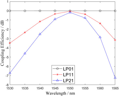
FIGURE 9. Coupling efficiency of each mode of our proposed MUX/DEMUX in the C-band.
Figure 10 gives the variation of the mode ER of our MUX/DEMUX with the incident light wavelength. The ERs of the modes LP01, LP11, and LP21 are indicated by the curves with the circles, asterisks, and triangles, respectively. The ER of mode LP11 is the average ER of the degenerate modes LP11a and LP11b. The ER of mode LP21 is the average one of the degenerate modes LP21a and LP21b. The ER of mode LP11 can be maintained above 31.66 dB in the whole C-band, with a maximum value of 34.97 dB at 1550 nm. The ER of LP21 mode is above 24.43 dB, with a maximum value of 31.60 dB at 1550 nm. The ERs of modes LP21 and LP11 are decreased on both sides of 1550 nm. The ER of LP01 mode is the best, while that of the degenerate mode LP11 is always better than that of the mode LP21.
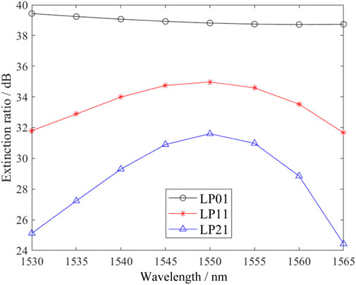
FIGURE 10. ER of each mode of our MUX/DEMUX in the C-band.
Combining the advantages of pure silica core, FMF ring-core, the directional coupling method, and the degenerate modes output, we use degenerate modes LP11a/LP11b and LP21a/LP21b as two independent channel signals and achieve the mode multiplexer/demultiplexer of LP01, LP11, and LP21 modes with the degenerate modes output, which can be used in MIMO-FREE applications. The pure silica core is used to achieve low loss performance, and the intrinsic loss of each mode can be better than 0.164 dB/km. Low crosstalk and high ER are achieved by using a ring core and a large effective refractive index difference. The coupling efficiency of mode LP01 is approximately 0 dB, which is almost unchanged with the increase of the wavelength. The coupling efficiency of LP11 is higher than −3.49 dB and that of LP21 is higher than −7.24 dB in the whole C-band. At 1550 nm, the coupling efficiencies of the modes LP01, LP11, and LP21 are −0.002, −0.052 dB, and −0.178 dB, respectively. The effective refractive index difference of each mode within 1.50–1.60 μm is maintained at 4.18 × 10⁻³, and the ER of each mode is maintained above 24.43 dB in the whole C-band and reaches above 31.60 dB at 1550 nm. The coupling efficiency and ER of LP01 mode are the best, while those of the degenerate mode LP11 are always better than those of the modes LP21. Our proposed MUX/DEMUX achieves low crosstalk and high ER performance and solves the problem caused by the degenerate modes rotations during transmission. It is expected to solve the challenges of the current research on the FMF MUX/DEMUX, which has important academic and application values.
The raw data supporting the conclusion of this article will be made available by the authors, without undue reservation.
HX contributed to data curation, formal analysis, validation, writing—original draft, and software. YS contributed to data curation, formal analysis, validation, writing—original draft, and software. YG helped with data curation, formal analysis, validation, writing—original draft, and software. XL assisted with conceptualization, project administration, supervision, funding acquisition, investigation, and methodology. HZ contributed to conceptualization, project administration, supervision, writing—review editing, funding acquisition, investigation, and methodology. CB helped with supervision, funding acquisition, investigation, and methodology. WH involved in supervision, funding acquisition, investigation, and methodology. HX assisted with supervision, funding acquisition, investigation, and methodology.
This work is supported in part by the National Natural Science Foundation of China (Grant Nos 61671227 and 61431009), the Shandong Provincial Natural Science Foundation (ZR2020MF012 and ZR2011FM015), and the Taishan Scholar Research Fund of Shandong Province.
The authors declare that the research was conducted in the absence of any commercial or financial relationships that could be construed as a potential conflict of interest.
All claims expressed in this article are solely those of the authors and do not necessarily represent those of their affiliated organizations, or those of the publisher, the editors, and the reviewers. Any product that may be evaluated in this article, or claim that may be made by its manufacturer, is not guaranteed or endorsed by the publisher.
1. Ellis AD, Zhao J, Cotter D. Approaching the non-linear Shannon limit. J Lightwave Technol (2010) 28(4):423–33. doi:10.1109/JLT.2009.2030693
2. Li G, Bai N, Zhao N, Xia C. Space-division multiplexing: The next frontier in optical communication. Adv Opt Photon (2014) 6(4):413–87. doi:10.1364/AOP.6.000413
3. Gao Y, Li Y, Xing H, Li X, Zheng H, Bai C, et al. Research on mode division multiplexing optical transmission. J Liaocheng Univ (Nat Sci Ed (2022) 35(1):30–56. doi:10.19728/j.issn1672-6634.2021040006
4. Du J, Shen W, Liu J, Chen Y, Chen X, He Z. Mode division multiplexing: From photonic integration to optical fiber transmission [invited]. Chin Opt Lett (2021) 19(9):091301. doi:10.3788/col202119.091301
5. Dong Q, Liu Y, Zheng H, Li X, Bai C, Hu W, et al. Research on mode (de)multiplexing technology for mode-division multiplexing system. J Liaocheng Univ (Nat Sci Ed (2020) 33(2):50–67. doi:10.19728/j.issn1672-6634.2020.02.008
6. Wang X, Zheng H, Li X, Liu Y, Yu R, Bai C, et al. Recent progresses on few mode fibers for mode-division multiplexing system. J Liaocheng Univ (Nat Sci Ed (2019) 32(2):69–79. doi:10.19728/j.issn1672-6634.2019.02.011
7. Zhang J, Wu X, Fan Q, Yi X, Tan Z, Li J, et al. High-capacity bi-directional full-duplex transmission based on fiber-eigenmode multiplexing over a FMF with 2×2 MIMO. Opt Express (2021) 29(19):30473. doi:10.1364/OE.433972
8. Gao Y, Li Y, Li X, Zheng H, Bai C, Hu W, et al. An elliptical-core few-mode fiber with low loss and low crosstalk for the MIMO-FREE applications. Front Phys (2022) 9. doi:10.3389/fphy.2021.796549
9. Li Y, Wang X, Zheng H, Li X, Bai C, Hu W, et al. A novel six-core few-mode fiber with low loss and low crosstalk. Opt Fiber Tech (2020) 57:102211. doi:10.1016/j.yofte.2020.102211
10. Nejad RM, Tavakoli F, Wang L, Guan X, LaRochelle S, Rusch LA. RoF data transmission using four linearly polarized vector modes of a polarization maintaining elliptical ring core fiber. J Lightwave Technol (2018) 36(17):3794–801. doi:10.1109/JLT.2018.2851613
11. Tomashuk AL, Kashaykin PF, Semjonov SL, Filippov AV, Bychkova EA, Galanova SV, et al. Comparison study of radiation-resistant polarization-maintaining PANDA fibers with undoped- and N-Doped-Silica core. J Lightwave Technol (2020) 38(20):5817–24. doi:10.1109/JLT.2020.3002651
12. Jung Y, Kang Q, Zhou H, Zhang R, Chen S, Wang H, et al. Low-loss 25.3 km few-mode ring-core fiber for mode-division multiplexed transmission. J Lightwave Technol (2017) 35(8):1363–8. doi:10.1109/JLT.2017.2658343
13. Wang Z, Lu Q, Tu J, Xiao Q, Shen L, Lan X, et al. Design, fabrication, and characterization of a low-index center and trench-assisted 7-ring-core 5-mode-group fiber for dense space-division multiplexing. Opt Express (2022) 30(1):650–63. doi:10.1364/OE.447823
14. Ge D, Gao Y, Yang Y, Shen L, Li Z, Chen Z, et al. A 6-LP-mode ultralow-modal-crosstalk double-ring-core FMF for weakly-coupled MDM transmission. Opt Commun (2019) 451:97–103. doi:10.1016/j.optcom.2019.06.015
15. Hasegawa T, Yamamoto Y, Tamura Y, Hayashi T, “Advances in ultra-low loss silica fibers, ” in, Frontiers in Optics 2016, OSA Technical Digest (online) (Optica Publishing Group, 2016), 2016, Paper FTu2B.2. doi:10.1364/FIO.2016.FTu2B.2
16. Tamura Y, Sakuma H, Yamamoto Y, Hasegawa T. Ultra-low loss silica core fiber for long haul transmission. In: Conference on lasers and electro-optics. San Jose, California (2018). p. SF2K.3. doi:10.1364/CLEO_SI.2018.SF2K.3
17. Dadabayev R, Malka D. A visible light RGB wavelength demultiplexer based on polycarbonate multicore polymer optical fiber. Opt Laser Technol (2019) 116:239–45. doi:10.1016/j.optlastec.2019.03.034
18. Gelkop B, Aichnboim L, Malka D. RGB wavelength multiplexer based on polycarbonate multicore polymer optical fiber. Opt Fiber Tech (2021) 61:102441. doi:10.1016/j.yofte.2020.102441
19. Sakaguchi J, Klaus W, Delgado Mendinueta JM, Puttnam BJ, Luis RS, Awaji Y, et al. Large spatial channel (36-core × 3 mode) heterogeneous few-mode multicore fiber. J Lightwave Technol (2016) 34(1):93–103. doi:10.1109/JLT.2015.2481086
20. Li Y, Hu Z, Benton DM, Ali A, Patel M, Ellis AD. Demonstration of 10-channel mode- and polarization-division multiplexed free-space optical transmission with successive interference cancellation DSP. Opt Lett (2022) 47(11):2742. doi:10.1364/OL.456235
21. Zhang H, Wang Z, Xi L, Du C, Zhang X, Li H, et al. All-fiber broadband multiplexer based on an elliptical ring core fiber structure mode selective coupler. Opt Lett (2019) 44(12):2994. doi:10.1364/OL.44.002994
22. Liu H, Wen H, Zacarias J, Antonio-Lopez J, Wang N, Sillard P, et al. Demonstration of stable 3x10 Gb/s mode group-multiplexed transmission over a 20 km few-mode fiber. In: Optical fiber communication conference. San Diego: California (2018). p. W4J.2. doi:10.1364/OFC.2018.W4J.2
23. Hu T, Li J, Ge D, Wu Z, Tian Y, Shen L, et al. Weakly-coupled 4-mode step-index FMF and demonstration of IM/DD MDM transmission. Opt Express (2018) 26(7):8356–63. doi:10.1364/OE.26.008356
24. Gasulla I, Kahn JM. Performance of direct-detection mode-group-division multiplexing using fused fiber couplers. J Lightwave Technol (2015) 33(9):1748–60. doi:10.1109/JLT.2015.2392255
25. Liu Y, Dong Q, Zheng H, Li X, Bai C, Hu W, et al. Research on a novel mode division multiplexer with low crosstalk, low loss and few mode ring-core transmission channel. Opt Commun (2020) 469:125778. doi:10.1016/j.optcom.2020.125778
26. Li J, Du J, Ma L, Li MJ, Jiang S, Xu X, et al. Coupling analysis of non-circular-symmetric modes and design of orientation-insensitive few-mode fiber couplers. Opt Commun (2017) 383:42–9. doi:10.1016/j.optcom.2016.08.051
27. Joseph T, John J. Two-core fiber-based mode converter and mode demultiplexer. J Opt Soc Am B (2019) 36:1987–94. doi:10.1364/JOSAB.36.001987
28. Zuo M, Ge D, Liu J, Gao Y, Shen L, Lan X, et al. Long-haul intermodal-MIMO-free MDM transmission based on a weakly coupled multiple-ring-core few-mode fiber. Opt Express (2022) 30(4):5868–78. doi:10.1364/OE.451971
29. Gao Y, Cui J, Jia J, Du C, Xia C, Liu Y, et al. A degenerate-mode-selective coupler for stable DSP-free MDM transmission. J Lightwave Technol (2019) 37(17):4410–20. doi:10.1109/JLT.2019.2925116
30. Zheng H, Li X, Liu S, Hu W, Bai C. Generation and transmission of a High-bit-rate optical millimeter wave with an unrepeated long single-span using equalization amplification. Opt Commun (2015) 356:599–606. doi:10.1016/j.optcom.2015.08.062
31. Wen H, Zheng H, Mo Q, Velázquez-Benítez AM, Xia C, Huang B, et al. Few-mode fibre-optic microwave photonic links. Light Sci Appl (2017) 8(6):e17021–8. doi:10.1038/lsa.2017.21
32. Zheng H, Li X, Bai C. Transmission of chirped pulse in optical fiber. Beijing: Sci Press (2018). p. 1–184. (in Chinese).
33. Wang X, Zheng H, Zhu L, Li X, Bai C, Hu W, et al. A long single-span dispersion-decreasing-like fiber transmission system. Opt Laser Technol (2019) 116:338–44. doi:10.1016/j.optlastec.2019.03.046
34. Zhang Z, Zhang F, Xu B, Xie H, Fu B, Lu X, et al. High-sensitivity gas detection with air-lasing-assisted coherent Raman spectroscopy. Ultrafast Sci (2022) 2022:1–8. doi:10.34133/2022/9761458
35. Fu Y, Cao J, Yamanouchi K, Xu H. Air-Laser-based standoff coherent Raman spectrometer. Ultrafast Sci (2022) 2022:1–9. doi:10.34133/2022/9867028
36. Qiao SD, Sampaolo A, Patimisco P, Spagnolo V, Ma YF. Ultra-highly sensitive HCl-LITES sensor based on a low-frequency quartz tuning fork and a fiber-coupled multi-pass cell. Photoacoustics (2022) 27:100381. doi:10.1016/j.pacs.2022.100381
37. Liu XN, Ma YF. Tunable diode laser absorption spectroscopy based temperature measurement with a single diode laser near 1.4 μm. Sensors (2022) 22:6095. doi:10.3390/s22166095
38. Ma YF, Lewicki R, Razeghi M, Tittel FK. QEPAS based ppb-level detection of CO and N_2O using a high power CW DFB-QCL. Opt Express (2013) 21(1):1008–19. doi:10.1364/OE.21.001008
39. Gao Y, Li J, Xia C, Liu Y, He Y, Chen Z, et al. Stable 4×10 Gb/s MIMO-free IM/DD MDM transmission enabled by Degenerate-mode-selective Couplers. In: Proceeding of the 2018 European Conference on Optical Communication (ECOC); September 2018; Rome, Italy. IEEE (2018). p. 3. doi:10.1109/ECOC.2018.8535512
40. Liu Y, Yang Z, Zhao J, Zhang L, Li Z, Li G. Intrinsic loss of few-mode fibers. Opt Express (2018) 26(2):2107. doi:10.1364/OE.26.002107
Keywords: mode-division multiplexing, mode-division multiplexer/demultiplexer, degenerate modes output, few-mode fiber ring-core, low crosstalk, low loss, MIMO-FREE
Citation: Xing H, Su Y, Gao Y, Li X, Zheng H, Bai C, Hu W and Xu H (2022) A novel mode-division (de)multiplexer with degenerate modes output for MIMO-FREE applications. Front. Phys. 10:1056639. doi: 10.3389/fphy.2022.1056639
Received: 29 September 2022; Accepted: 18 October 2022;
Published: 10 November 2022.
Edited by:
Yufei Ma, Harbin Institute of Technology, ChinaReviewed by:
Dror Malka, Holon, Institute of Technology (HIT), IsraelCopyright © 2022 Xing, Su, Gao, Li, Zheng, Bai, Hu and Xu. This is an open-access article distributed under the terms of the Creative Commons Attribution License (CC BY). The use, distribution or reproduction in other forums is permitted, provided the original author(s) and the copyright owner(s) are credited and that the original publication in this journal is cited, in accordance with accepted academic practice. No use, distribution or reproduction is permitted which does not comply with these terms.
*Correspondence: Hongjun Zheng, MzcwMTEyNDE4QHFxLmNvbQ==
†These authors have contributed equally to this work
Disclaimer: All claims expressed in this article are solely those of the authors and do not necessarily represent those of their affiliated organizations, or those of the publisher, the editors and the reviewers. Any product that may be evaluated in this article or claim that may be made by its manufacturer is not guaranteed or endorsed by the publisher.
Research integrity at Frontiers
Learn more about the work of our research integrity team to safeguard the quality of each article we publish.