 Mesfin Belayneh*
 Bernt Aadnøy*
- Department of Energy and Petroleum Engineering, University of Stavanger, Stavanger, Norway
In drilling wells, lost circulation, barite sagging, shale swelling, and formation damage are critical problems for the industry. These problems can be controlled by designing appropriate drilling fluids and lost circulation materials. In this study, the performance of 80/20 and 60/40 oil-based drilling fluids (OBMs) was compared based on the lost circulation materials’ (LCMs) bridging performance, filtrate loss, barite sagging, and shale stability. The results show that in terms of LCM stability, the performance of LC-LUBE improved when blended with mica. Both drilling fluids inhibit shale swelling. The overall analysis showed that the 60/40 OBM is better and recommended.
1 Introduction
Borehole instability problems occur during the drilling, completion, and production phases. Although in the past much progress has been made to solve the problem, it remains a challenging issue for the oil industry. The two main factors causing borehole instability are classified as mechanical and chemical effects. The physical–chemical fluid–rock interaction phenomena modify the near-wellbore rock strength. The main mechanisms are hydration, osmotic pressures, swelling, rock softening, and strength changes [1]. Knowledge of these helps for modeling and simulation of a wellbore stability study.
Drilling in natural fractures, highly permeable formation, and vugular and cavernous rocks, as well as drilling-induced fractures, result in undesired fluid loss, which is commonly called lost circulation. This could occur during drilling and cementing operations. Depending on the rate of losses, circulation losses are classified as seepage, partial, severe, or total circulation losses. Since the classification of circulation losses is not globally standardized, various classifications are documented by different authors [2–5]. A drilling-induced fracture occurs as the well pressure causes the minimum stress around the wellbore to exceed the tensile strength of the formation. Well fracturing can be controlled by designing appropriate mud density and fluid properties (rheology and chemistry) that control the possible pore pressure build-up to reduce the well strength-weakening effect. However, when it comes to natural fractures, vugs, and cavern openings in dolomites and limestones, they exist in situ. Therefore, lost circulation is prevented or controlled by using lost circulation control materials (LCMs), which creates a self-healing/sealing mechanism in case the drilling formation contains micro-fractures.
Studies from the deep-water environments in the Gulf of Mexico showed that about one-third of the overall NPT incidents are due to lost circulation (>10%), kick (>10%), and stuck pipe (>10%) [6]. On average, the non-productive time associated with wellbore instability problems increases the drilling time by 15% [7], and Ref. [8] also reported that NPT increases the cost in the range of 10–20%.
Literature-documented laboratory experimental results have shown that lost circulation materials (LCMs) decrease fluid losses and also increase the wellbore strengthening effects [9–20]. The fracture initiation and propagation experimental studies conducted by [21] showed that both the OBM and water-based drilling fluid (WBM) recorded a similar fracture initiation pressure. However, the reopening pressures with the WBM fluids were higher. The authors interpreted the experimental data that the water-based fluids have fracture healing capability. Reference [22] presented experimental data from fracturing experiments using oil-based drilling fluids. The authors proposed operational guidelines and showed significant differences between oil- and water-based drilling fluids. Over the years, several experimental studies have been carried out at the University of Stavanger with penetrating and non-penetrating fluids. The results have shown that the penetrating fluids build up the formation pressure and, hence, recorded a lower fracturing pressure than the non-penetrating fluid [23]. This shows that the drilling fluid with a good sealing capacity at the face of the wellbore increases the wellbore strength. The sealing capacity of the drilling fluid is determined by how good enough the drilling fluid additives are to create a stronger and impermeable mud cake. Moreover, the fracturing pressure with three different commercial water-based drilling fluids’ results showed that the fracturing pressure depends on the drilling fluids, which is associated with the quality of the mud cake it forms on the wellbore [24].
Recently, the applications of nanoparticles (1–100 nm size) have shown impressive performance in drilling fluids, cement, and enhanced oil recovery. Compared with microparticles such as LCM, the surface area-to-volume ratio of the nanoparticle is extremely high [25]. The impact of nanoparticles on OBM and WBM showed an improved rheological property [26–29], filtrate loss, and filter cake thickness reduction [26–31], plugging the pore spaces of shale and, hence, reducing its permeability [32–34], improving the lubricity [27, 28, 35–37], increasing the wellbore strength [38], enhancing the electrical conductivity and thermal conductivity of the conventional drilling fluids [39–43], and inhibiting shale swelling [44, 45]. When it comes to wellbore strength, Ref. [38] reported that the addition of an optimal blend of iron III hydroxide nanoparticles and micro-sized graphite with a water-based drilling fluid increased the fracture strength by 70%. The fracture strength increased by 36% as the optimal calcium carbonate nanoparticles blended with micro-sized graphite in the oil-based drilling fluid. These results could be due to the improvement of the cake and the fluid’s lost reduction properties as well, which reduced the communication between the well and the formation. Moreover, as reported in references [ 32–34], the plugging of the nanoparticles in shale inhibits water absorption and hence minimizes the shale swelling issue.
From the reviewed materials, the sealing/bridging performance of particulates (nano/micro) at a given fracture width depends on the type of the drilling fluid to be interacted with, the particle concentration, types, sizes, and the mechanical and chemical properties of the particles as well. The overall effect is associated with the strength of the LCM bridging in the mud cake. Oil-based drilling fluids are effective in maintaining wellbore stability and lubrication, which is suitable for drilling long-reach wells. However, oil-based drilling fluids are expensive and not environmentally friendly. The issues addressed in this study are the performances of the 80/20 and 60/40 OBMs concerning LCM stability at fracture gates, sagging potential, filtrate loss, and shale swelling inhibition performances. The comparisons of the two mud systems will be investigated through the single LCM and the blending of LCMs to investigate the effect of particle synergy.
2 Literature study
2.1 Lost circulation management
The commonly used methods to manage lost circulation are categorized as preventive and remedial action [3]. LCM and techniques are used to combat circulation loss problems. LCM testing and developing the best designs are the key to successful lost circulation management. The remedial action is conducted based on the severity of the loss rates in the formation.
2.1.1 Preventive treatments
Preventive actions include using wellbore strengthening materials, drilling fluid selections, and best drilling practices. The reviewed materials indicate that the micro-sized LCM [46] and nanoparticle-based LCMs [38] increased the wellbore strength. Moreover, the bridging performance of the LCM particles assessed at the artificial slot and also the lost circulation material prevents huge mud loss by bridging at the gate of the fracture. The key elements for a good preventive method (i.e., wellbore strengthening and preventing losses) depend on selecting the right particle size spectrum, particles’ mechanical strength, shape, and size along with their interaction with the drilling fluids as well.
2.1.2 Remedial treatments
The remedial treatments for lost circulation management are performed by using lost circulation materials. The design of the LCM depends on the severity of the loss. The lost circulation cure/hindrance can be conducted by conditioning the drilling fluid with lost circulation materials or by using stop-loss pills. In this study, the preventive performance of pure LC-LUBE and mica and their mixture will be experimentally evaluated to investigate the synergy of particles. Different companies do have their own lost circulation treatment decision tree. When the loss is severe, the pill system is designed based on fibers, flakes, and particles that will be blended with a drilling fluid. However, before the application of the pill system, it is important to evaluate the LCM’s bridging strength and optimize the design as well through an experimental study.
2.2 Lost circulation material selection approaches
The selection of a proper particle size, shape, and concentration along with a high-resilience LCM is of significant importance to achieve an effective bridge at the fracture gate. In the drilling fluid industry, theories have been developed to determine optimum particle sizes, namely, based on the ideal packing theory and particle size distribution (PSD). Based on the particle size distribution, the approaches to optimize bridging blends to seal the formation surface are based on D90, D50, and D10. The LCM selection approaches are documented in [47–50]. On the other hand, the ideal packing theory concept states that the median pore size can be estimated from the permeability by taking the square root of the permeability. The pore size is the median size of the pores, which is known as D50 [51]. The packing of the particle is affected by the size distribution and shape of the particles.
2.3 Lost circulation materials
In the industry, several lost circulation materials (LCMs) are developed and are in use. The LCMs are of particles, flaky, fibrous, and mixtures. Several investigators have reviewed the types and their bridging performance as well [52–58]. In this study, LC-LUBE (graphite), mica, and their blending are evaluated in two different oil-based drilling fluids. Both have different mechanical, structural, lubricity, and hardness properties. The particles are used in the industry.
2.4 Mud cake deposition and mechanism of particle bridging at the fracture gate
Due to differential pressures on a wellbore, particles and cuttings in a drilling fluid are filtered out and deposited in/at the gate fractures and on the wall of a wellbore (Figure 1). The filter cake eventually controls the flow between the well and the formation.
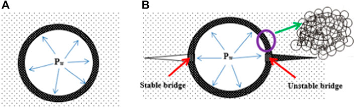
FIGURE 1. (A) Before fracturing and mud cake (particle deposition). Figure 1(B): After fracturing, the stable/unstable bridge at the fracture wings.
Figure 1 shows particle deposition on the wall of the unfractured wellbore (Figure 1A) and after wellbore fracturing at the fracture wings (Figure 1B). When a wellbore fractures, the mechanical strength and stability of the bridging at the mouth of the fracture play a key role in hindering the mudflow and healing the fracture to strengthen the wellbore.
The frictional force between the particles and the drilling fluid’s properties such as viscosity and the coefficient of friction determines the net contact force between particles in a mud cake. At the right wing of the fracture (Figure 1B), stable bridging disconnects a pressure communication between the wellbore and the fracture tip. At the left wing of the fracture, the collapsed bridge allows pressure communication between the well and the fracture tip. The pressure applied on the walls of the fracture causes the fracture tip to grow and results in mud loss.
When particles plug at the gate of the fracture, the state of stress changes. The concept of stress caging due to particle deposition is shown in Figure 1B. Stress caging is the suggested mechanism for wellbore strengthening, which is by increasing the hoop stress around the borehole [46].
Studies at the University of Stavanger also indicated the importance of LCM properties and the developed plastic deformation of the filter cake as fracturing occurs. The strength of bridging depends on several factors including the mechanical and structural properties and concentration of the particles along with the drilling fluid properties.
Wellbore fracture, in general, occurs when the hoop stress exceeds the tensile strength of the wellbore. The hoop stress is a function of the wellbore pressure. In the presence of a mud cake, Aadnøy et al. presented a qualitative description of the fracturing process, which includes the fracture initiation, growth, and particle bridging phenomenon at the gate of the fracture [7].
3 Experimental design
Results obtained from several LCM bridging tests conducted at the University of Stavanger showed that the LCM plug fractures quite well when the fracture width size is around the D50 value of the PSD and the concentration of particles is about 5% by wt. of the drilling fluid. This is in line with Ref. [50]. However, the bridging performance of LCMs also depends on the characteristics of the particles (i.e., size, shape, hardness, and lubricity) and the drilling fluid. Experiments also showed that the blending of particles creates positive and negative synergies resulting in mechanically weak and stronger bridges, respectively. The selection of the right particle mix in terms of type and concentration is investigated through several experimental tests.
3.1 Material and methods
3.1.1 Lost circulation materials
Quantifying the particle size and shape is important to evaluate the bridging performances of lost circulation materials. In this study, the effect of mica, LC-LUBE, and their blending in 80/20 and 60/40 OBMs is investigated at different fracture slots.
LC-LUBETM is a synthetic graphite particulate and is used as a fluid lost material. Mechanically, on the Mohs scale, the hardness of graphite is about 1–2. This allows the particle to be easily deformed at the gate of the fracture and shows a good bridging property [46]. The blending of LC-LUBE in drilling fluids has also a function as a solid lubricant. Figure 2 shows a scanning electron microscope (SEM) picture which provides an insight into the structure of the particles. As can be seen from the SEM, the LC-LUBE (Figure 2A) particle is an irregular crystalline structure with a rough surface.
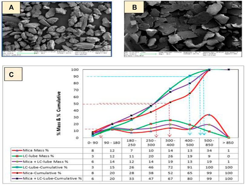
FIGURE 2. SEM picture of LC-LUBE (A) and mica (B), and cumulative particle size distribution (size is in micrometer) (C).
Mica is an aluminosilicate mineral. The SEM picture shows that the mica particle (Figure 2B) is irregular with a sheet or plate-like structure. Mica forms flat six-sided crystals with a significant cleavage in the direction of large surfaces, which permits them to easily split into flat films. Its hardness on the Mohs scale is 2–4.
To quantify the particle size distribution (PSD), a sieved analysis was performed. The particle cumulative weight percentage and the retention percentage are shown in Figure 2C. From the curve, one can observe the D10 values of all the particles lying within the same spectrum (0–90 μm). The D50 values of LC-LUBE and mica are within 250–300 μm and 300–400 μm, respectively, and their mixture is within 250–300 μm. The drilling fluids contain a weight material, barite. The particle size distribution of barite shows small sizes. The PSD of barite showed that D10, D50, and D90 values are 1.51 μm, 14.52 μm, and 65.18 μm, respectively.
3.1.2 Drilling fluid-1 for lost circulation material and swelling evaluation
For the LCM performance study, two 1.75 sg oil-based mud systems with 80/20 and 60/40 oil-to-water ratios (OWRs) were prepared. The formulation is according to M-I SWACO, which is typically used for drilling operations.
3.1.2.1 Drilling fluid-1 for lost circulation material, filtrate loss, and shale swelling evaluation
The drilling fluid-1 chemical composition analysis results showed that the brines (water-to-salt ratio) of the drilling fluid systems are about 2.2, which is to obtain equal water phase salinity. The barite-to-water ratio of the 80:20 OBM is about twice that of the 60:40 OBM. Table 1 shows the viscometer responses of the drilling fluids measured at room temperature and the calculated Bingham plastic and power-law rheological parameters. Results showed that the Bingham plastic viscosity (PV), yield strength (YS), and lower shear stress (LSYS) of the 60/40 OBM are 1.6, 1.7, and 1.2 times higher than those of the 80/20 OBM, respectively. The power-law flow index parameters show closer values. On the other hand, the consistency index value of the 60/40 OBM is about 75% higher than that of the 80/20 OBM.
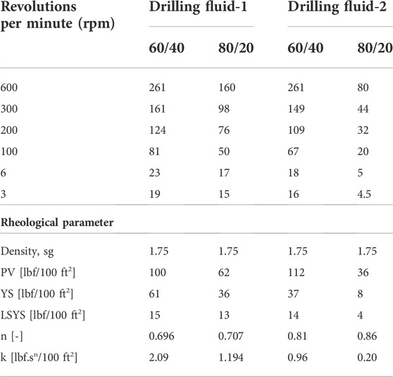
TABLE 1. Measured viscometer, density, and the calculated rheological parameters of drilling fluids.
3.1.2.2 Drilling fluid-2 for barite sagging evaluation
For the sagging evaluations, 60/40 and 80/20 OBM drilling fluids were obtained from M-I SWACO. The drilling fluids have the same density, which is 1,750 kg/m3, and different oil-to-water ratios (OWRs). Analysis of the chemical compositions of drilling fluid-2 showed that the brines (water-to-salt ratio) of the two drilling fluid systems are the same to obtain equal water phase salinity. The barite-to-water ratio of the 80:20 OBM is about twice that of the 60:40 OBM. As shown in Table 1, the calculated Bingham plastic viscosity (PV), yield strength (YS), and lower shear stress (LSYS) of the 60/40 OBM are 3.1, 4.6, and 3.5 times higher than those of the 80/20 OBMs, respectively. Except for the flow index, the power-law parameters such as the consistency index of the 60/40 OBM is 4.55 times higher than that of the 80/20 OBMs.
3.1.3 Characterization methods
3.1.3.1 Lost circulation material bridging mechanical testing
Figure 3 shows a schematic diagram of the LCM bridging test experimental setup built at the University of Stavanger. The dimensions of the cylindrical drilling fluid holder (5) are 35 mm and 64 mm for the inner and outer diameters, respectively, and 150 mm long. The reason for the single-slot design was to simulate the fractured wing, as shown in Figure 1. The depth of the slots is 10 mm, and the length is 24.4 mm. The drilling fluid blended with the LCM filled in the drilling fluid holder forms a mud cake (4) at the gate of the slot (7), as shown at the fracture wings (Figure 1). The pressure response applied by the Gilson pump (2) on the mud cake was recorded using PC-control LabVIEW (1). The work process is as follows:
• First, we tested the system’s maximum pressure that the experimental setup can hold without showing leakage during the testing and found it to be 50 MPa. We, therefore, set the maximum pressure limit during testing to be 50 MPa.
• From experience, we observed that LCM testing over 25 min sometimes showed water breakthrough. This is due to many bridge collapses resulting in both LCM and drilling fluid losses. We, therefore, limited the testing to 25 min. We stop testing once the bridge pressure reaches the maximum limit. There is no API-standardized LCM testing procedure/guideline. Therefore, the purpose of the experimental work was just to evaluate the LCMs’ performances in the drilling fluids under the considered temperature and the LCM (type and concentration) concerning the selected slot sizes.
• In order not to modify the rheological properties and the density of the drilling fluid, we added 2.5 g LCM to the 180 g drilling fluid. Converting this in pounds per gallon, it was 8.49. Different investigators recommended the size and concentration of LCM along with the fracture width. However, the selection of the LCM in this study is around the one proposed for flakes and particles by Howard and Scott [58].
• The selection of slot sizes was based on the ideal packing theory concept, which is the D50 value of the PSD of the LCMs (Figure 2), as suggested by Ref. [51]. The slots used for testing are 300μm, 400 μm, and 500 μm, which are above and below the D50 values.
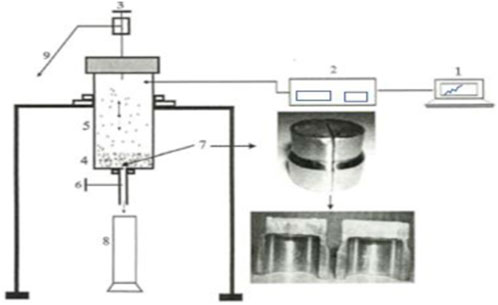
FIGURE 3. Schematic particle bridging testing experimental setup.
3.1.3.2 Viscometer rheological properties
The viscosity of the drilling fluids is measured using the Fann 35 viscometer. Using the measured dataset, the rheological parameters were calculated with the Bingham plastic [59] and power-law models [59] and the Herschel–Bulkley model [60, 61] for comparison purposes.
3.1.3.3 Barite sagging
For the qualification of the drilling fluid in terms of bridging stability, it is also imperative to evaluate the sagging behaviors of the drilling fluids. The sag index is one of the methods used to assess the sagging potential. The dynamic sag measurement and sag factor determination are according to the M-I SWACO procedure. In the VG-viscometer heating cup, the drilling fluid is allowed to maintain the temperature at 50°C. The bob was rotated at 100 rpm for 40 min. From the bottom of the cup, 20 ml of the sagged fluid was taken and the weight was measured. The sag factor determination was from the sagged fluid, and the initial mud weight is calculated as follows:
The change in density is calculated as follows:
where mfinal is the mass of the fluid taken after testing, minitial is the mass of the fluid taken before testing, and volume is the sample volume.
3.1.3.4 Shale swelling
A total of eight diverse types of synthetic pellets were used to study the swelling and disintegration behavior of shales in the drilling fluids presented in Section 3.1.2.1. Of these, six of the pellet types were prepared based on the literature data. Pierre, Texas, and Devonian shale compositions were obtained from Ref. [62], and three smectite-rich North Sea shales (A, B, and C) were obtained from Ref. [63]. This study’s pellet type (I and II) contains a high concentration of bentonite. Except for the bentonite-I type, all the pellets were prepared by mixing bentonite and non-clay minerals (feldspar, quartz, and calcite) with water. After 24 h, the mixture was filled in a cylindrical-shaped tube and was pressed by hand to make pellets. The state of stress and the compaction strength will not represent the in situ condition. However, working on weak pellets is something like a worst-case scenario (which is soft, highly porous, and permeable pellets). The bentonite pellet type-I was prepared by pressing dry bentonite using a presser up to 10 bar. It is to be noted that the pellets used for the analysis in this study are modified versions of the ones proposed by Ref. [62] and Ref. [63], regardless of the formation fluid properties but only based on the mineralogical composition of the shales.
3.1.3.5 Static high-temperature and pressure filter test
To evaluate the filtrate loss of the two considered drilling fluids, a static high-temperature and pressure test was conducted. The drilling fluid was heated up to 100°C, and the applied differential pressure was 500 psi.
3.1.3.6 Rheological parameter determination
Bingham plastic model [59]: The model is described by plastic viscosity and yield stress parameters. According to the model, the shear stress varies linearly as the shear rate increases. The model reads as follows:
The Bingham plastic (PV) and the yield stress (YS) are calculated from the 300 and 600 rpm viscometer dial readings, respectively, as follows:
Power-law model [59]: According to the model, the shear stress varies in the power law as the shear rate increases. The model reads as follows:
where the parameters n and k describe the drilling fluid flow index and consistency index, respectively.
Herschel–Bulkley model [60]: The Herschel–Bulkley model is a modified power-law model described by three parameters. According to the model, the fluid requires minimum applied pressure to set the fluid in motion when the shear rate is zero, and it is defined by a lower shear yield stress, τy. The model reads as follows:
Zamora and Power [61] calculated the lower shear yield stress, LSYS, (τy) as follows:
where
4 Result and discussion
4.1 Lost circulation material bridging test
4.1.1 The performance of LC-LUBE in the oil-based drilling fluids
For the drilling fluid lost circulation hindrance study, an 8.49 ppb LC-LUBE particle was mixed with the two selected drilling fluids. Bridging tests were conducted at 300 μm, 400 μm, and 500 μm slots. The D50 value is within the range of 250–350 microns. Figures 4–6 show the test results. For a given particle concentration, as the fracture width increases and the size is higher than the D50 value, the particle becomes unstable and flows through the slots. Consequently, the bridging efficiency is reduced. From all tests, one can observe that the performance of the two mud systems is comparable. This could be the fact that the fluid flow between the particles has a comparable coefficient of friction. Moreover, the reason for the bridge instability is due to the lubricity behavior of the LC lube. In general, it is important to remember that the bridging performance of particles depends on different parameters such as particle types, sizes, concentrations, and mechanical properties such as hardness and lubricity, which provide different results. Moreover, the chemistry of the particulate–drilling fluid may affect the particle–particle contact which as a result may affect the bridge stability.
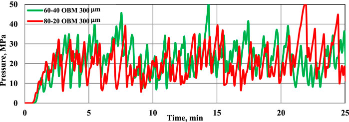
FIGURE 4. Bridging test at the 300-μm slot.
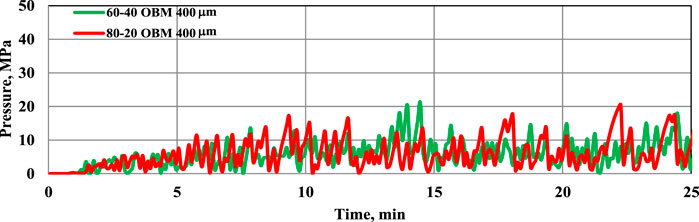
FIGURE 5. Bridging test at the 400-μm slot.
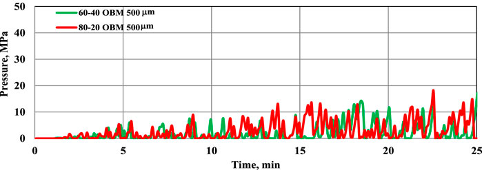
FIGURE 6. Bridging test at the 500-μm slot.
4.1.2 The performance of mica in the oil-based drilling fluids
As can be seen from the PSD (Figure 3), the D50 value is in the range of 300–400 microns. The majority of the mass % concentration (about 34%) is within 500–800 microns. The particle test results are shown in Figures 7–9. Compared with the test results obtained from LC-Lube (Figures 4–6), it can be seen that mica performs well showing a stable bridging pressure profile. The reason could be due to the wide particle size spectrum.
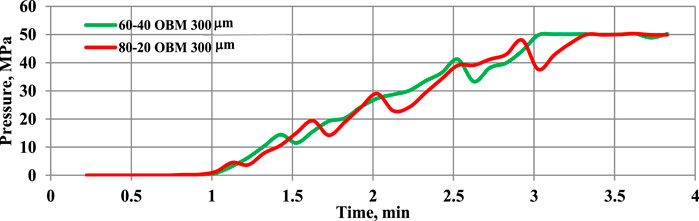
FIGURE 7. Bridging test at the 300-μm slot.
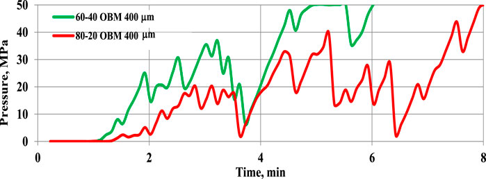
FIGURE 8. Bridging test at the 400-μm slot.
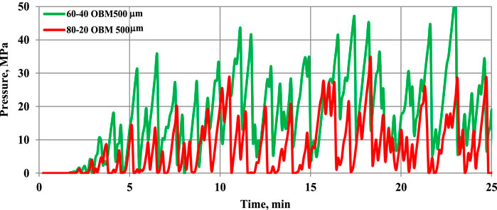
FIGURE 9. Bridging test at the 500-μm slot.
4.1.3 Comparisons of the 80/20 and 60/40 OBMs in different lost circulation material systems
The experimental pressure profile shows a zigzag shape, which is due to the formation and the collapse of a bridge at the mouth of the fracture. When sufficient LCM is deposited at the gate of the fracture, the bridge carries the applied load and the fluid will not be lost through the slot. The response of the bridge is the pressure building up and showing a positive slope, as shown in Figures 4–9. The pressure build-up phenomenon is called the bridging pressure. When the wellbore pressure reaches a certain critical peak value at which the bridge will not be able to carry the loading, the bridge will then collapse and result in a pressure drop (i.e., negative slope). As a result of the bridge collapse, the fluid will be lost through the slot. The degree of collapse varies. The measured dataset shows that when the bridge completely collapses, the pressure drops to zero and results in more fluid losses. On the other hand, when part of the bridge collapses and the LCM then quickly repairs the bridge, the pressure may not be reduced to zero but shows a minor reduction. The bridge healing process occurred as the LCM-laden fluid flows through the slot. The best analogy for unstable and stable bridges, along with the fluid loss and hindrance mechanisms, is shown in Figure 1B.
During LCM testing, the probability of particles’ arrival at the gate of the fracture (in terms of concentration and size) varies from time to time. As we can see, the zigzag pressure behavior varies over testing time. To obtain more information and make a good evaluation, Mostafavi et al. [64] have analyzed the LCM bridging experimental data based on the number of peaks, the average of the maximum peaks, the maximum pressure, and the average pressure over the test period. For better comparisons of the performance of the LCMs in the two mud systems, in this study, we just chose to present the average pressure over the test period. The average pressure is the measure of the mean of the bridge and collapse pressures during the test period.
Figures 10–12 show the comparisons of the LCM bridging performance in the two drilling fluids. The results show that the strength of the LC-LUBE LCM in the drilling fluids is quite similar. On the other hand, mica shows different performances. This shows that the particle–drilling fluid interaction could be one factor when studying the mechanical strength of the mud cake. However, the detail and reason for this level of research are beyond the scope of this study.
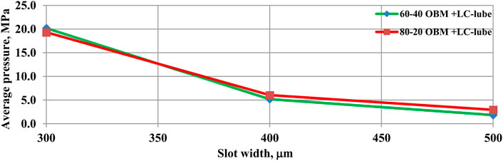
FIGURE 10. Comparisons of 8.48-ppb LC-LUBE-treated 80/20 and 60/40 OBM systems.
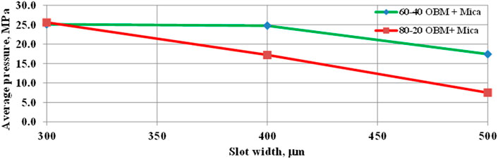
FIGURE 11. Comparisons of 8.48-ppb mica-treated 80–20 and 60–40 OBM systems.
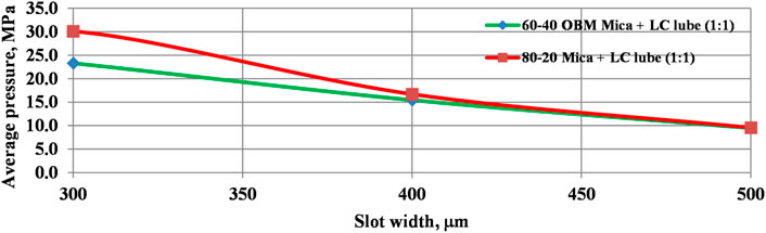
FIGURE 12. Comparisons of 8.48-ppb LC-LUBE + mica (1:1 ratio)-treated 80/20 and 60/40 OBM systems.
4.1.4 Comparisons of the single LCM and the blending of lost circulation materials
To assess the synergy of LCMs, mica and LC-LUBE were mixed in a 1:1 ratio. The PSD and mass % concentration are shown in Figure 3, which is in between LC-LUBE and mica. The blended LCM contains both flat and irregularly shaped particulates. The D50 value is within the range of 250–300 μm, which is the same as that of the LC-LUBE particle. Compared with the separate test results performed with LC-LUBE (Figures 4–6), it can be shown that the addition of mica improves the pressure profile. However, compared with the single mica test results (Figures 7–9), the addition of LC-LUBE reduced the stability. The reason could be that the lubricity of LC-LUBE might have reduced the friction at the grain–grain contact at the fracture gate. Figures 13– Figure 14 show the analysis of the different LCM (separate and blending) stabilities in the two mud systems separately. As shown, the size, mechanical, lubricity, and physical properties of particle additives are the major factors for the bridging strength and stability.
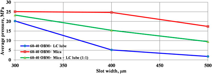
FIGURE 13. Bridging performance of the 60/40 OBM treated with 8.49 ppb LC-LUBE, mica, and a mixture of mica and LC-LUBE.
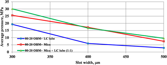
FIGURE 14. Bridging performance of the 80/20 OBM treated with 8.49 ppb LC-LUBE, mica, and a mixture of mica and LC-LUBE.
4.2 Barite sagging analysis
The rheological parameters, the dynamic sagging factor, and the change in the density of the drilling fluids are measured at 50°C. Scott et al. [65] have presented three field case studies to investigate sag occurrence and control methods. The study showed that the drilling fluid with an insufficient lower shear yield stress (LSYS) experiences a higher sagging tendency. The authors recommended an effective method to reduce sag tendencies by maintaining the LSYS value in the range of 7–15 lbf/100 sqft. From the measured rheological parameters, the LSYS of the 60/40 OBM is calculated to be 12 lbf/100 sqft, which is within the recommended range, and the LSYS of the 80/20 OBM is 4 lbf/100 sqft, which is below the recommended range. The change in the density of the 60/40 OBM and 80/20 OBM is 0.0888 sg, and 0.1887 sg, respectively.
According to Maxey [66], the sagging potential of the drilling fluid is higher when the sag factor is greater than 0.53. The dynamic sag test results showed that the sag factor of the 60/40 OBM is 0.52, which is below the sag limit, and the sag factor of the 80/20 OBM is 0.56, which is above the sag limit.
4.3 Filtrate loss
In the drilling well, the drilling fluid experiences elevated temperature and pressure. These thermodynamic variables affect the rheological and physical properties of the drilling fluid. The higher temperature decreases the viscosity and the density of the fluid. Moreover, the fluid–solid phase separation will also increase. As a result, higher filtration rates will cause formation damage and the fluid property will also be changed. The cumulative filtrate loss collected during the 30-min testing results showed that the 60/40 OBM recorded 2.2 ml and the 80/20 OBM recorded 4.0 ml. The reason for the lower filtrate loss could be due to the reduction of the permeability/porosity of the mud cake, the reduction of the fluid–solid separation, and the higher viscosity of the filtrate. These parameters can be quantified through measurement and the Darcy law. Interested readers may refer to the study by Awais et al. (2020) [67].
4.4 Swelling inhibition of the drilling fluids
A total of eight pellets were synthesized, and their swelling phenomenon is investigated by immersing them in the 60/40 and 80/20 OBM drilling fluids. During testing, the pellets were immersed in the drilling fluids for 4 days. Results show that none of the pellets swelled, fractured, or disintegrated. By visual inspection and nail scratch testing, the strengths of the pellets are the same in the two drilling fluids.
5 Summary
Lost circulation occurs during the well construction process. It is one of the most challenging problems and costs the industry a lot. Investigators have tested several LCMs along with recommendations for the application. However, to have a better understanding of the bridging process, it is imperative to evaluate the performance of the LCM in the type of fluid systems to be mixed with.
In this study, the performance of 60/40 and 80/20 oil-based mud systems was compared. The analysis was based on bridging performance, shale stability, filtrate loss, and sagging effect to quantify the fluid for the application. Based on the overall analysis, results are as follows:
• The LC-LUBE bridging performance is quite similar in both fluid systems. This could be due to the lubricity of the fluids and the particle–particle grain contact being comparable.
• The performance of mica shows good bridging as compared with that of LC-LUBE.
• The performance of LC-LUBE is improved when blended with mica. This could be the mechanical, shape, size, and other properties that might play a role in improving the bridge’s stability.
• The bridging stability in the 60/40 OBM is better than that in the 80/20 OBM.
• In terms of shale stability, both mud systems inhibit the shale swelling phenomenon.
• For field application, the experimental results reveal that it is important to test the performance of LCMs separately and their mixture to investigate positive synergy, as shown by mixing LC-LUBE with mica. Moreover, the selection of the LCM size, concentration, and testing at a slot should be based on the expected field formation fracture size. The LCM should also be tested by blending with the expected field drilling fluids to be used.
• The drilling fluids’ performance analysis results show that the 60/40 OBM is better in terms of sagging, bridging stability, and filtrate loss. This agrees with the conclusion of [68].
6 Future work
It should be noted that the experimental work results presented in the study are valid for the considered testing temperature and pressures, the drilling fluids, the LCM types, and the concentration. Changing any one of these may produce a different result. The results obtained in the study are not a conclusion but a summary of the observation. To gain more insight into the understanding of the LCM performance and barite sagging issues, in the future, we plan to conduct testing at elevated pressure and temperature, among others:
• Dynamic barite sagging and filtrate loss.
• Change the drilling fluids from the OBM to WBM and consider 70/30 and 90/10 OBMs.
• Change the LCM types and PSD.
Data availability statement
The raw data supporting the conclusions of this article will be made available by the authors, without undue reservation.
Author contributions
The paper is the result of the equal contribution of the authors in writing, experimental design as well as interpretation. MB: Contributions are experimental test design, testing, writing and interpretation. BA: Contributions are LCM experimental setup-design and construction, experimental test design, writing and interpretation.
Acknowledgments
The authors acknowledge the University of Stavanger for the materials and the laboratory access.
Conflict of interest
The authors declare that the research was conducted in the absence of any commercial or financial relationships that could be construed as a potential conflict of interest.
Publisher’s note
All claims expressed in this article are solely those of the authors and do not necessarily represent those of their affiliated organizations, or those of the publisher, the editors, and the reviewers. Any product that may be evaluated in this article, or claim that may be made by its manufacturer, is not guaranteed or endorsed by the publisher.
Supplementary material
The Supplementary Material for this article can be found online at: https://www.frontiersin.org/articles/10.3389/fphy.2022.1042242/full#supplementary-material
References
1. Mc Lellan PJ, Wang Y. Predicting the effects of pore pressure penetration on the extent of wellbore instability: Application of a versatile poro-elastoplastic model. Delft, The Netherlands: Eurock SPE/ISRM Rock Mechanics in Petroleum Engineering (1994). p. 29–31.
3. Cook J, Growcock F, Guo Q, Hodder M, Van oort E. Stabilizing the wellbore to prevent lost circulation. Oilfield Review (2011).
4. Al-Yami A, Wagle V, Al-Anqari K, Aljohar A. Salah elkatatny//Curing losses: Lab developments and best practices. In: International Petroleum Technology Conference Paper presented at the International Petroleum Technology Conference; February 21–23, 2022; Riyadh, Saudi Arabia (2022). Paper Number: IPTC-22007-MS.
5. Hitchcock G. Additive manufactured shapes used to cure total lost circulation events. In: Publisher: Offshore Technology Conference Paper presented at the Offshore Technology Conference; May 4–7, 2020; Houston, Texas, USA (2020).
6. Pilisi N, Wei Y, Holditch SA. Selecting drilling technologies and methods for tight gas sand reservoirs, IADC/SPE 128191. In: Proceedings of the 2010 IADC/SPE Drilling Conference held in New Orleans; 2–4 February 2010; LA, USA (2010).
8. Redden J. Advanced fluid systems aim to stabilize well bores, minimize nonproductive time. The Am Oil Gas Reporter (2009) 52(8):58–65.
9. Nayberg TM. Laboratory study of lost circulation materials for use in both oil-based and water-based drilling muds. SPE Drill Eng (1986) 2:229–36. doi:10.2118/14723-PA
10. Soroush H, Sampaio JHB. Investigation into strengthening methods for stabilizing wellbores in fractured formations. In: Proceedings of the 2006 SPE Annual Technical Conference and Exhibition; September 24–27, 2006; San Antonio, Texas (2006).
11. Fuh GF, Morita N, Boyd PA, McGoffin SJ. A new approach to preventing lost circulation while drilling. In: Proceedings of the 67th Annual Technical Conference and Exhibition of the Society of Petroleum Engineers; October 4–7, 1992; Washington, DC (1992).
12. Ivan CD, Bruton JR, Thiercelin M, Bedel J. Making a case for rethinking lost circulation treatments in induced fractures. In: Proceedings of the 2002 SPE Annual Technical Conference and Exhibition; September 29–October 2, 2002; San Antonio, Texas (2002).
13. Scott PP, Lummus JL. New developments in the control of lost circulation//SPE 516-G. In: Proceedings of the 30th Annual Fall Meeting of the Petroleum Branch of the American Institute of Mining and Metallurgical Engineers; October 2–5, 1955; New Orleans (1955).
14. Whitfill DL, Hemphill T. Pre-treating fluids with lost circulation materials. Drilling Contractor (2004).
15. Alsaba M, Nygaard R, Saasen A, Nes O. Lost circulation materials capability of sealing wide fractures. In: SPE deepwater drilling and completions conference; September 10–11, 2014; Galveston (2014).
16. Alsaba M, Nygaard R, Saasen A, Nes O. Laboratory evaluation of sealing wide fractures using conventional lost circulation materials. In: SPE annual technical conference and exhibition; October 27–29, 2014; Amsterdam (2014).
17. Alsaba M, Nygaard R, Saasen A, Nes O. Experimental investigation of fracture width limitations of granular lost circulation treatments. Pet Explor Prod Technol (2016) 6:593–603.
18. Clapper DK, Szabo JJ, Spence SP, Otto MJ, Creelman B, Lewis TG, McGuffey G. One sack rapid mix and pump solution to severe lost circulation. In: SPE/IADC drilling conference and exhibition; March 1–3, 2011; Amsterdam (2011).
19. Kefi S, Lee JC, Shindgikar ND. Optimizing in four steps composite lost-circulation pills without knowing loss zone width. In: Asia Pacific drilling technology conference and exhibition; November 1–3, 2010; Ho Chi Minh (2010).
20. Kageson-Loe N, Sanders MW, Growcock F, Taugbøl K, Horsrud P, Singelstad AV, et al. Particulate-based loss-prevention material-the secrets of fracture sealing revealed. SPE Drill & Compl (2009) 24(04):581–9.
21. Morita N, Black AD, Fuh GF. Theory of lost circulation pressure. In: Proceedings of the 65th Annual Technical Conference and Exhibition of the Society of Petroleum Engineers; September 23–26, 1990; New Orleans, LA (1990).
22. Onyia EC. Experimental data analysis of lost-circulation problems during drilling with oil-based mud. SPE Drill & Compl (1994) 9(01):25–31.
23. Aadnøy BS. Geomechanics analysis for deepwater drilling.//SPE 39392. In: IADC/SPE Drilling Conference; March 3–6, 1998; Dallas, TX (1998).
24. Aadnøy BS, Belayneh M. Elasto-plastic fracturing model for wellbore stability using non-penetrating fluids. J Pet Sci Eng (2004) 45:179–92. doi:10.1016/j.petrol.2004.07.006
25. Amanullah MD, Al-Tahini MA. Nano-technology—its significance in smart fluid development for oil and gas field application//SPE-126102-MS. In: Proceedings of the Saudi Arabia Section Technical Symposium; May 9–11, 2009; Al-Khobar, Saudi Arabia (2009).
26. Vryzas Z, Zaspalis V, Nalbantian L, Mahmoud O, Nasr-El-Din HA, Kelessidis VC. A comprehensive approach for the development of new magnetite nanoparticles giving smart drilling fluids with superior properties for HP/HT applications, IPTC-18731-MS. In: Proceedings of the International Petroleum Technology Conference; 14–16 November 2016; Bangkok, Thailand (2016).
27. Sadeghalvaad M, Sabbaghi S. The effect of the TiO2/polyacrylamide nanocomposite on water-based drilling fluid properties. Powder Technol (2015) 272:113–9. doi:10.1016/j.powtec.2014.11.032
28. Mohamadian N, Ghorbani H, Wood DA, Khoshmardan MA. A hybrid nanocomposite of poly (styrene-methyl methacrylate-acrylic acid), clay as a novel rheology-improvement additive for drilling fluids. J Polym Res (2019) 26:33. doi:10.1007/s10965-019-1696-6
29. Mohamud O, Mady A, Aftab ASDA. Al2O3 and CuO nanoparticles as promising additives to improve the properties of KCl-polymer mud: An experimental investigation. Can J Chem Eng (2021) 2021:1–14. doi:10.1002/cjce.24285
30. Mohamadian N, Ghorbani H, David Wood A, Khoshmardan MA. Rheological and filtration characteristics of drilling fluids enhanced by nanoparticles with selected additives//An experimental study. Adv Geo-energy Res (2018) 2:228–36. doi:10.26804/ager.2018.03.01
31. Aftab A, Ali M, Sahito MF, Mohanty US, Jha NK, Akhondzadeh H, et al. Environmental friendliness and high performance of multifunctional tween 80/ZnO-nanoparticles added water-based drilling fluid: An experimental approach. ACS Sustain Chem Eng (2020) 8:11224–43. doi:10.1021/acssuschemeng.0c02661
32. Sharma MM, Zhang R, Chenevert ME, Ji L, Guo Q, Friedheim J. A new family of nanoparticle-based drilling fluids, SPE-160045-MS. In: Proceedings of the SPE Annual Technical Conference and Exhibition; 8–10 October 2012; San Antonio, TX, USA (2012).
33. Hoelscher KP, de Stefano G, Riley M, Young S. Application of nanotechnology in drilling fluids, SPE- 157031-MS. In: Proceedings of the SPE International Oilfield Nanotechnology Conference and Exhibition; June 12–14, 2012; Noordwijk, The Netherlands (2012).
34. Gao C, Miska SZ, Yu M, Ozbayoglu EM, Takach NE. Effective enhancement of wellbore stability in shales with new families of nanoparticles, SPE-180330-MS. In: Proceedings of the SPE Deepwater Drilling and Completions Conference; 14–15 September 2016; Galveston, TX, USA (2016).
35. Taha NM, Lee S. Nano graphene application improving drilling fluids performance, IPTC-18539-M. In: Proceedings of the International Petroleum Technology Conference; 6–9 December 2015; Doha, Qatar (2015).
36. Awais M, Belayneh M, Saasen A, Fjelde KK, Aadnøy S. Effect of MWCNT and MWCNT functionalized –oh and -cooh nanoparticles in laboratory water based drilling fluid. In: Proceedings of the ASME 2017 37th International Conference on Ocean, Offshore and Arctic Engineering; 17–22 June 2018; Madrid, Spain (2018).
37. Sabah A, Alswasiti A, Salam M. Improving drilling fluid properties at high-pressure conditions using selected nanomaterials. IOP Conf Ser : Mater Sci Eng (2019) 579:012004. doi:10.1088/1757-899x/579/1/012004
38. Nwaoii CO, Hareland G, Husein M, Nygaard R, Zakaria ME. Wellbore strengthening-nano-particle drilling fluid. Experimental design using hydraulic fracture apparatus, SPE-163434. In: Proceedings of the SPE/IADC Drilling Conference; 5–7 March 2013; Virtual, Amsterdam, The Netherlands (2013).
39. Halali MA, Ghotbi C, Tahmasbi K, Ghazanfari MH. The role of carbon nanotubes in improving thermal stability of polymeric fluids: Experimental and modeling. Ind Eng Chem Res (2016) 55:7514–34. doi:10.1021/acs.iecr.6b00784
40. William JKM, Ponmani S, Samuel R, Nagarajan R, Sangwai JS. Effect of CuO and ZnO nanofluids in Xanthan gum on thermal, electrical, and high-pressure rheology of water-based drilling fluids. J Pet Sci Eng (2014) 117:15–27. doi:10.1016/j.petrol.2014.03.005
41. Hassani SS, Amrollahi A, Rashidi A, Soleymani M, Rayatdoost S. The effect of nanoparticles on the heat transfer properties of drilling fluids. J Pet Sci Eng (2016) 146:183–90. doi:10.1016/j.petrol.2016.04.009
42. Fazelabdolabadi B, Khodadadi AA, Sedaghatzadeh M. Thermal and rheological properties improvement of drilling fluids using functionalized carbon nanotubes. Appl Nanosci (2015) 5:651–9. doi:10.1007/s13204-014-0359-5
43. Ponmani S, Nagarajan R, Sangwai JS. Effect of nanofluids of CuO and ZnO in polyethylene glycol and polyvinylpyrrolidone on the thermal, electrical, and filtration-loss properties of water-based drilling fluids. SPE J (2016) 21:405–15. doi:10.2118/178919-pa
44. Boul PJ, Reddy BR, Zhang J, Thaemlitz C. Functionalized nanosilicas as shale inhibitors in water-based drilling fluids. SPE Drilling & Completion (2017) 32:121–30. doi:10.2118/185950-pa
45. Kang Y, She J, Zhang H, You L, Song M. Strengthening shale wellbore with silica nanoparticles drilling fluid. Petroleum (2016) 2:189–95. doi:10.1016/j.petlm.2016.03.005
46. Aston MS, Alberty MW, McLean MR, de Jong HJ, Armagost K. Drilling fluids for wellbore strengthening//IADC/SPE 87130. In: IADC/SPE Drilling Conference; 2-4 March 2004; Dallas, Texas (2004).
47. Abrams A Mud design to minimize rock impairment due to particle invasion. J Pet Technol (1977) 29(05):586–592. doi:10.2118/5713-pa
48. Smith P, Browne SV, Heinz TJ, Wise WV. Drilling fluid design to prevent formation damage in high permeability Quartz arenite sandstones. In: Proceedings of the SPE Annual Technical Conference; 6–9 October 1996; Denver, CO, USA (1996).
49. Vickers S, Cowie M, Jones T, Twynam AJ A new methodology that surpasses current bridging theories to efficiently seal a varied pore throat distribution as found in natural reservoir formations. Wiertnictwo, Nafta, Gaz (2006) 23(1):501–515.
50. Whitfill D. Lost circulation material selection, particle size distribution and fracture modeling with fracture simulation software//SPE-115039-MS. In: IADC/SPE Asia Pacific drilling technology conference and exhibition; August 25–27, 2008; Jakarta, Indonesia (2008).
51. Dick M, Heinz TJ, Svoboda CF, Aston M Optimizing the selection of bridging particles for reservoir drilling fluids. In: SPE International Symposium on Formation Damage Control; February 23–24, 2000; Lafayette, Louisiana (2000).
53. Alkinani HH, Abo Taleb Al-Hameedi , Dunn-Norman S, Mustafa A, Al-Alwani , Mutar RA, Al-Bazzaz WH. State-of-the-Art review of lost circulation materials and treatments. In: Part I: General Trends and Uses/Paper presented at the Abu Dhabi International Petroleum Exhibition & Conference; November 11, 2019; Abu Dhabi, UAE (2019). Paper Number: SPE-197393-MS.
54. Alkinani HH, Al-Hameedi ATT, Dunn-Norman S, Waleed H, Al-Bazzaz . State-of-the-Art review of lost circulation materials and treatments. In: Part II: Probability and Cost Analyses Paper presented at the International Petroleum Technology Conference; January 13–15, 2020; Dhahran, Kingdom of Saudi Arabia (2020).
55. Alkinani HH. A comprehensive analysis of lost circulation materials and treatments with applications in Basra's oil fields, Iraq: Guidelines and recommendations. MSc Thesis. United States: Missouri University Of Science And Technology (2017).
56. Alsaba M, Nygaard R, Hareland G, Contreras O. Review of lost circulation materials and treatments with an updated classification. In: AADE fluids technical conference and exhibition; 15–16 April, 2014; Houston (2014).
57. Alkinani HH, Al-Hameedi AT, Flori RE, Dunn-Norman S, Hilgedick SA, Alsaba MT. Updated classification of lost circulation treatments and materials with an integrated analysis and their applications. In: Paper presented at the SPE Western Regional Meeting; April 22–26, 2018; Garden Grove, California, USA (2018).
58. Howard GC, Scott PP An analysis and the control of lost circulation. J Pet Technol (1951) 3(06):171–82. doi:10.2118/951171-g
59.API. Api rp 13D. In: Recommended practice on the rheology and hydraulics of oil-well drilling fluids. 4th ed. Washington, D.C., United States: American Petroleum Institute (1995).
60. Gucuyener IH. A rheological model for drilling fluids and cement slurries. In: SPE 11487-MS Middle East Oil Technical Conference and Exhibition; 14-17 March 1983; Bahrain (1983).
61. Zamora M, Roy S, Slater K. Comparing a basic set of drilling fluid pressure-loss relationships to flow-loop and field data. In: AADE-05-NTCE-27 presented at the AADE 2005 National Technical Conference and Exhibition; 5-7 April, 2005; Houston (2005).
62. Chenevert ME, Osisanya SO. Shale/mud inhibition defined with rig-site methods. SPE Drilling Eng (1989) 4:261–8. doi:10.2118/16054-pa
63. Horsrud P, Bostrom B, Sonstebo EF, Holt R. Interaction between shale and water-based drilling fluids: Laboratory exposure tests give new insight into mechanisms and field consequences of KCl contents. In: SPE 48986, SPE Annual Technical Conference and Exhibition, New Orleans; 27-30 September 1998; Louisiana (1998).
64. Mostafavi V, Hareland G, Belayneh M, Aadnoy BS. Mechanistic modeling of fracture sealing resistance with respect to fluid and fracture properties. In: Paper presented at the 45th U.S. Rock Mechanics/Geomechanics Symposium; June 26–29, 2011; San Francisco, California (2011).Experimental and
65. Scott PD, Mario Z, Catalin A. Barite-sag management: Challenges, strategies, opportunities//SPE-87136-MS. In: IADC/SPE Drilling Conference; 2-4 March, 2004; Dallas, Texas (2004).
66. Maxey J. Rheological analysis of static and dynamic sag in drilling fluids. Annu Trans Nordic Rheology Soc (2007) 15.
67. Alvi MAA, Belayneh M, Bandyopadhyay KKS. Effect of hydrophobic iron oxide nanoparticles (Fe2o3)On the properties of 90/10 oil based drilling fluids. In: Proceedings of the ASME 2020 39th International Conference on Ocean, Offshore and Arctic Engineering OMAE2020; June 28-July 3, 2020; Fort Lauderdale, FL, USA (2020).
Keywords: LCM, LC-lube, 80/20 OBM, 60/40 OBM, sagging, swelling, bridging
Citation: Belayneh M and Aadnøy B (2022) Bridging performances of lost circulation materials (LC-LUBE and mica) and their blending in 80/20 and 60/40 oil-based drilling fluids. Front. Phys. 10:1042242. doi: 10.3389/fphy.2022.1042242
Received: 12 September 2022; Accepted: 17 October 2022;
Published: 17 November 2022.
Edited by:
Chong Lin, CCDC Drilling & Production Technology Research Institute, ChinaCopyright © 2022 Belayneh and Aadnøy. This is an open-access article distributed under the terms of the Creative Commons Attribution License (CC BY). The use, distribution or reproduction in other forums is permitted, provided the original author(s) and the copyright owner(s) are credited and that the original publication in this journal is cited, in accordance with accepted academic practice. No use, distribution or reproduction is permitted which does not comply with these terms.
*Correspondence: Mesfin Belayneh, bWVzZmluLmEuYmVsYXluZWhAdWlzLm5v; Bernt Aadnøy, YmVybnQuYWFkbm95QHVpcy5ubw==