 Mingliang Long
 Haifeng Zhang1,2
 Rong Zong Yu
94% of researchers rate our articles as excellent or good
Learn more about the work of our research integrity team to safeguard the quality of each article we publish.
Find out more
BRIEF RESEARCH REPORT article
Front. Phys. , 24 October 2022
Sec. Optics and Photonics
Volume 10 - 2022 | https://doi.org/10.3389/fphy.2022.1036346
This article is part of the Research Topic Miniaturized High-Power Solid-state Laser and Applications View all 23 articles
Satellite laser ranging (SLR) had been operated at a pulse repetition frequency (PRF) from ∼10 Hz to 10 kHz; the ultra-high PRF of SLR (UH-SLR) is a trend of development. In this study, an alternate working mode of laser firing and gated pulse bursts is proposed to solve the problem of laser echo interference by laser backscattering. Through an ultra-high PRF of 200-kHz picosecond green laser with single-pulse energy of 80 μJ and a pulse width of 10 ps and a ranging gate device, UH-SLR has been built by an aperture of the 60-cm SLR system in the Shanghai Astronomical Observatory. By this UH-SLR, low-orbit to high-orbit and geostationary orbit satellites are measured night and day and also for low-orbit and medium-orbit satellites in the daytime. The normal point (NP) accuracy is ∼30 μm for low-orbit satellites and ∼100 μm for high-orbit satellites, which provides an effective method for the development of ultra-high PRF and high-precision space target laser ranging.
Satellite laser ranging (SLR) is applied to acquire the distance from satellites to ground stations with the time-of-flight measurement [1–4]. Its ranging accuracy is up to a millimeter or even more, which is a key source of information for satellite geodes [5–10]. A precise orbit determination (POD) can be obtained by SLR [6]; it is an original contribution to testing and verifying relativistic physics [11]. The post-fit root-mean-square residuals of the POD were 8.81 cm with 49 normal points (NPs) for Quasi-Zenith Satellite 1, and also, the corresponding three-dimensional orbital overlap error for 4 days was 160.564 m [10]. At present, the picosecond laser plays an important role in SLR. The pulse repetition frequency (PRF) of the kilohertz (kHz) picosecond laser was more widely used to provide more ranging measurement data and higher ranging accuracy [3, 6, 9]. The high PRF of laser ranging has the characteristic of a fast target search; it can increase the number of echoes within the ranging measurement NPs to obtain higher precision, so it has been rapidly developed [2, 3, 12–17]. In 2018, the Shanghai Astronomical Observatory (SHAO) analyzed the ranging data to show that the NP ranging accuracy at a PRF of 4 kHz was about 2.62 times higher than that of 1 kHz [12]. In the following year, the 10-kHz laser ranging from a low orbit to a geostationary orbit was realized by upgrading the laser and distance gate device [3].
The ultra-high PRF (above 100 kHz) of SLR (UH-SLR) is mainly realized by pulse bursts and the single-photon detector (SPAD). A small fiber nanosecond laser was used to achieve a PRF of 100 kHz UH-SLR, whose measured range was up to 20,000 km, and the NP ranging accuracy was 5∼15 mm; this ranging system size was only 1.8 × 1.2 × 1.6 m with a weight of 200 kg [14, 15]. At the Global Technology Conference organized by the International Laser Ranging Service (ILRS) in Stuttgart, D. Dequal analyzed the NP ranging accuracy at a PRF of 100 kHz. UH-SLR was expected to be at a sub-millimeter level [16]; after a few years, they had realized 100 kHz UH-SLR [17]. The SLR station in Graze reported a PRF of 500 kHz UL-SLR, and a few years later, they achieved a PRF of 1 MHz UH-SLR in 2021 [2]. A PRF of 100 kHz lunar laser ranging was built by Vladimir Zharov in Russia to obtain a sub-millimeter ranging accuracy. The aperture of the telescope was 2.5 m with 150 W in a PRF of 150 kHz pulse laser [18]. However, for UH-SLR, the laser backscattered (LBS) under laser transmission in the atmosphere very easily interferes with the laser echoes, which increases the difficulty of laser echo identification [19]. In this study, pulse bursts in the alternating mode are proposed to solve the question of the LBS, and also, the SPAD with low noise worked in the Geiger mode.
The radar link equation is the basis of evaluating the measurement capability for the SLR system; the equation is as follows [20]:
where n0 is the average photo-electrons produced by laser echoes from satellites, λ is the wavelength of the laser, h is the Planck’s constant, c is light velocity, ηq is the quantum efficiency of the SPAD, Et is single-pulse laser energy, Ar is the effective receiving area of the telescope, AS is the reflection area of the reflector, T is the laser transmission efficiency in the atmosphere, Kt is the efficiency of the transmitting optical telescope, Kr is the efficiency of the receiving optical telescope, α is the attenuation factor, θt is the divergence of the laser beam, θt is the reflector divergence angle on satellites, and R is the distance from ground stations to satellites. When the SPAD detects background and dark noise, the laser echoes from satellites will not be detected, so the detection probability of the laser echoes from the satellite is as follows:
where n1 is the background photon noise and n2 is the dark photon noise by the SPAD. It can be seen from the aforementioned formula that in order to improve the detection probability of n0, n1 and n2 should be reduced. Under the PRF of f and combined with the radar link (1), the average number of laser echo points N per unit of time is as follows:
From the aforementioned formula, in order to increase the average number of laser echo points N, the PRF of laser ranging should be increased. At the same time, supposing N is constant, increasing the PRF can reduce the single-pulse energy of the laser or the effective receiving area of the system, so a small-aperture telescope and a low-pulse energy laser with a high PRF can be used for SLR, like the minimal SLR system in [14].
The single-ranging accuracy of the SLR system is estimated as follows [14–17]:
σL is the time deviation caused by the pulse width of the laser, σD1 is the deviation of opening time with the SPAD gate, σD2 is the deviation of SPAD closing time of the gate, σET is the event timer response deviation, and σs is the impulse response deviation of the ranging target. At present, the ILRS uses NPs to reflect the ranging accuracy, and the calculation formula is as follows [12, 17, 20]:
where N is the number of data points in the NP duration time, which is defined by the ILRS (https://ilrs.gsfc.nasa.gov/data_and_products/data/npt/index.html). From Eq. 5, it is observed that the PRF of raised SLR can increase the number of echoes in N so that a higher NP ranging accuracy can be obtained.
Under UH-SLR, because the PRF is up to 100 kHz (the space-time of laser pulses is 10 μs), the space-time between the laser pulses is short. The LBS from the laser pulse transmission in the atmosphere is relatively strong, and also, the continuing time of the LBS would be more than 10 μs. If the SPAD is opened at the continuing time of the LBS, on one hand, it is easy to cause the SPAD to be saturated and damaged; on the other hand, the LBS will interfere with the laser echoes from satellites; when the SPAD detects photons from the LBS, photons from laser echoes cannot be detected, which will increase the identification difficulty for SLR [19]. The LBS will be avoided in our mode of alternating pulse bursts. The working mode is shown in Figure 1A. The laser outputs pulse bursts, and it stops from a ranging gate device (RGD). Since the output of the laser has stopped, the SPAD is turned on to collect laser echoes from satellites; therefore, it avoids the interference of the LBS. After the SPAD receives the laser echoes, it then stops working, while at this time, the laser would be emitted, so this cycle repeats again; it is shown in Figure 1B.
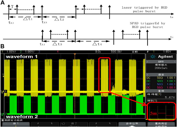
FIGURE 1. Time sequence of the alternated working mode for laser emission and the SPAD triggered (A) and pulse burst periodic signal (B) by the RGD.
In Figure 1A, the maximum continuous working time of the trigger signal for pulse bursts is as follows:
where c is the speed of light and L is the distance between the satellite and the SLR station, which varies with the azimuth and elevation of the satellite. The maximum number of pulses emitted from the laser is as follows:
where T is the period of the laser PRF; at this time, there is no external trigger signal within △t2, so the laser pulse is not emitted; however, the SPAD is turned on by the gate pulse burst signal from the RGD. The continuous working time △t3 of the corresponding SPAD is equal to △t2, and △t2 is equal to △t1, so the pulse burst period TL of the laser output is as follows:
For satellites with different orbital distances, the corresponding pulse burst periods can be obtained from Eq. 8. For example, for a satellite with a distance of 37,500 km from the SLR station, the pulse burst period TL will be 500 ms, the alternating frequency is 2 Hz, and the maximum time of pulse emission within the corresponding burst is 250 ms; for a PRF of 200 kHz, T is 5 μs, so the maximum number of pulses emitted from the laser is 50,000. In the actual ranging process, the satellite distance is changed, so TL would be changed. For different satellite orbit prediction distances, the repetition frequency of the pulse bursts and the number of pulses in the bursts can be calculated according to Eqs 7 and 8. We design an RGD for our UH-SLR using this. The pulse burst periodic signal of geostationary orbit satellites is generated by RGD, as shown in Figure 1B; waveform 1 is the pulse bursts of the laser ignition signal generated by Eq. 7, and waveform 2 is the SPAD trigger signal generated by Eq. 8; the interval between pulses for waveform 1 and 2 is 5 μs.
Taking the SLR system at the SHAO as a platform with the basic framework of laser ranging in [21], the block diagram of UH-SLR is shown in Figure 2.
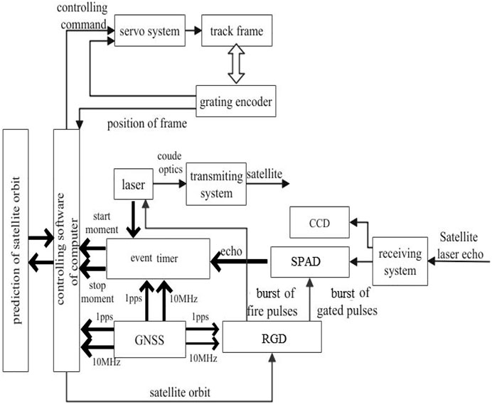
FIGURE 2. Diagram for the UH-SLR system.
In Figure 2, the satellite orbit prediction parameters are downloaded to the controlling software of the computer, and it is converted to a controlling command for the servo system, which controls the telescope mount to track the satellite with an accurate feedback track from the grating encoder. The satellite would be monitored by the receiving system’s monitoring charge-coupled device (CCD). At this time, the laser is ignited by the burst fire of pulses from the RGD, through the coupé optics and transmitting system to the satellite, and also, the laser pulse is processed by using a photoelectric detector, and it is sent to the event timer (ET). The ET (USB, A033 origin Latvia) would start to record and send the start time of laser pulses t1 to the computer. Bursts of gate pulses from the RGD would be sent to the SPAD (by East China Normal University, China). Spectral filtering (0.15 nm) and spatial filtering are performed to reduce background noise. When the laser pulses are emitted, the SPAD is turned off, and when the SPAD is turned on, the laser pulse would be stopped; thus, it realizes the alternating mode of pulse burst sending and receiving. The laser echoes pass through the receiving system to the SPAD, and the return time t2 is obtained by the ET. Altogether, the RGD, computer, and ET are provided high precision time from the GNSS′ clock. Considering the delay of △t0 from the UH-SLR system, the range of satellite R is as follows:
A PRF of the 200-kHz picosecond laser is used, the average output power of the laser is 16 W, the single-pulse energy is 80 uJ, and the pulse width is 10ps. Based on the aperture of the 60-cm SLR system at the SHAO (as shown in Figure 3A), the UH-SLR system is established; UH-SLR software is shown in Figure 3B. Under the coordinated universal time (UTC) in the SHAO, satellite measurement data processing with satellites Jason3 in the low orbit, Glonass105 in the high orbit, and Compassi5 in the geostationary orbit, Lageos2 is ∼6000 km away, as shown in Figure 4, respectively. The satellite Lageos2 (Figure 4D) is measured in the UTC time of 8:42:04; this is daytime for the SHAO in the east eight time zones. The laser echoes in Figure 3 show that the SPAD operates in an alternate way, and it reflects the alternate mode of sending and receiving pulse bursts.
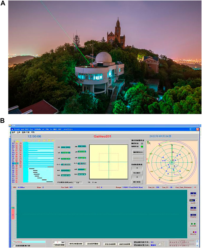
FIGURE 3. SLR system: (A)aperture of 60 cm at the SHAO (mountain of SheShang in Shanghai city); (B) software for UH-SLR.
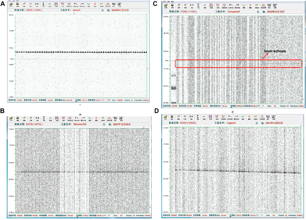
FIGURE 4. Measurement data processing for the satellite Jason3 (A), Glonass105 (B), Compassi5 (C), and Lageos2 (D) with UH-SLR at the SHAO.
Many satellites are measured during the night and daytime, as shown in Table 1; a part of the global navigation satellite system for Russia (Glonass), China (Beidou), and Europe (Galileo) is measured, especially the satellite Compassi5, which is about 37,000 km away. The single-ranging accuracy root mean square (RMS) is around 1 cm. The best NP ranging accuracy is 29 um with the satellite of Stella, and the satellite of Glonass132 is up to 113 μm. Compared with the NP ranging accuracy of the fiber nanosecond laser [15, 16], it achieves an order of magnitude improvement, which shows the advantages of a picosecond laser in UH-SLR.
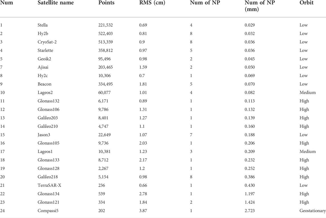
TABLE 1. Ranging data results for satellites from the UH-SLR system at the SHAO.
According to the radar link equation, the relationship between the average number of laser echoes, PRF, and the echo detection probability per unit of time is obtained. The SLR transmission time period with UH-SLR is separated from the laser echoes to solve the LBS interference; UH-SLR is achieved at the SHAO with a picosecond laser and RGD. Low- to high-orbit and geostationary orbits are measured night and day, and Lageos1 (about 6,000 km far away) is realized in the daytime. The NP ranging accuracy is up to 29 μm for low-orbit satellites and 113 μm for high-orbit satellites. Through the research and experiment in this study, pulse bursts in the alternating mode will become an effective method to realize UH-SLR, which strongly promotes the development and application of laser ranging technology.
The original contributions presented in the study are included in the article/Supplementary Material; further inquiries can be directed to the corresponding author.
ML conceived the project. ML, HZ, RY, ZW, and SQ conducted the experiment. ML and RY wrote the manuscript, and all authors contributed to discussions during its preparation. ZZ supervised the project.
This work was supported by the National Natural Science Foundation of P. R. China (12003056), the Natural Science Foundation of Shanghai (20ZR1467500), and the Shanghai Science and Technology Innovation Action (21142201900).
The authors declare that the research was conducted in the absence of any commercial or financial relationships that could be construed as a potential conflict of interest.
All claims expressed in this article are solely those of the authors and do not necessarily represent those of their affiliated organizations, or those of the publisher, the editors, and the reviewers. Any product that may be evaluated in this article, or claim that may be made by its manufacturer, is not guaranteed or endorsed by the publisher.
1. Steindorfer MA, Kirchner G, Koidl F, Wang P, Jilete B, Flohrer T. Daylight space debris laser ranging. Nat Commun (2020) 11:3735. doi:10.1038/s41467-020-17332-z
2. Wang P, Steindorfer MA, Koidl F, Kirchner G, Leitgeb E. Megahertz repetition rate satellite laser ranging demonstration at Graz observatory. Opt Lett (2021) 46:937. doi:10.1364/ol.418135
3. Long M, Zhang H, Meng L, Wu Z, Deng H, Qin S, et al. Satellite laser ranging at high-repetition 10 kHz in all day[J]. J.Infrared Millim Waves (2020) 39:778∼785.
4. Bai Z, Chen H, Gao X, Li S, Qi Y. Highly compact nanosecond laser for space debris tracking. Opt Mater (2019) 98:109470. doi:10.1016/j.optmat.2019.109470
5. Strugarek D, Sonica K, Arnold D, Jäggi A, Zajdel R, Bury G. Satellite laser ranging to GNSS-based Swarm orbits with handling of systematic errors[J]. GPS Solutions (2022) 26:104. doi:10.1007/s10291-022-01289-1
6. Zhang z, Cheng z, Zhang h, Zhao g, Deng h, Wu z Global laser ranging observation of Beidou Satellites and data application[J]. Chin J Lasers (2017) 44:1–9.
7. Zhang L, Sun W. Progress and prospect of GRACE Mascon product and its application. Rev Geophys Planet Phys (2022) 53:18.
8. Song C, Liang ZP, Lin HY, Zhao CY, Dong HP. Rotation state estimation of slow-rotating multi-reflector defunct spacecraft through laser ranging measurements from a single short arc. Celest Mech Dyn Astron (2022) 134:30. doi:10.1007/s10569-022-10083-7
9. Kucharski D, Kirchner G, Lim H-C, Koidl F. Optical response of nanosatellite BLITS measured by the Graz 2 kHz SLR system. Adv Space Res (2011) 48:1335–40. doi:10.1016/j.asr.2011.06.016
10. Oh H, Park E, Lim H-C, Lee S-R, Choi J-D, Park C Orbit determination of high-earth-orbit satellites by satellite laser ranging[J]. Astron Space Sci (2017) 34:271–9. doi:10.5140/JASS.2017.34.4.271
11. Ulrich Schreiber K, Jan K. The application of coherent local time for optical time transfer and the quantification of systematic errors in satellite laser ranging. Space Sci Rev (2018) 214:22. doi:10.1007/s11214-017-0457-2
12. Deng H, Zhang H, Long M, Wu Zhibo 吴, Tang Kai 汤, Zhang Zhongping 张. 4 kHz repetition rate satellite laser ranging system and its application. 光学学报 (2019) 39:0314002. doi:10.3788/aos201939.0314002
13. Sung K-P, Choi E-J, Lim H-C, Kim IY, Choi JS. Development of operation software for high repetition rate satellite laser ranging. J Korean Soc Aeronaut Space Sci (2016) 44:1103–11. doi:10.5139/jksas.2016.44.12.1103
14. Daniel H, Paul W, Schafer E, Riede W (2018). Concept for a new minimal SLR system[C]. 21st International Laser Ranging Workshop. Canberra, Australia.
15. Schafer D, Sproll E, sproll F, Otsubo T, Wagner P, Riede W. Satellite laser ranging at 100 kHz pulse repetition rate. CEAS Space J (2019) 11:363–70. doi:10.1007/s12567-019-00247-x
16. Dequal D, Agnesi C, Sarrocco D, Amoto LS, Cumis MS, Vallone G, et al. 100 kHz satellite laser ranging demonstration at Matera Laser Ranging Observatory[C]. ILRS Technical Workshop. Stuttgart, Germany (2019).
17. Dequal D, Agnesi C, Sarrocco D, Calderaro L, Santamaria Amato L, Siciliani de Cumis M, et al. 100 kHz satellite laser ranging demonstration at Matera Laser Ranging Observatory. J Geod (2021) 95:26. doi:10.1007/s00190-020-01469-2
18. Zharov V, Milyukov V, Ivlev O. Sub-millimeter lunar laser ranging: Novel approach to moon reference frame[C]. 21st International Laser Ranging Workshop. Canberra,Australia (2018). Available at: https://cddis.nasa.gov/lw21/docs/2018/presentations/Session9_Zharov_presenta-tion.pdf.
19. Iqbal F, Kirchner G, Koidl F, Leitgeb E. Laser back scatter: Limitation to higher repetition rate [kHz] Satellite Laser Ranging system. Geodesy and Geodynamics (2021) 12:48–53. doi:10.1016/j.geog.2020.08.002
20. Zhang C, Gao T, Cao Y, Fan Z, Fu H, Gu DF, et al. The facilities and performance of TianQin laser ranging station. Class Quan Gravity (2022) 39:125005. doi:10.1088/1361-6382/ac6d3e
Keywords: satellite laser ranging (SLR), picosecond laser, laser backscatter, pulse bursts, ultra-high pulse repetition frequency
Citation: Long M, Zhang H, Yu RZ, Wu Z, Qin S and Zhang Z (2022) Satellite laser ranging at ultra-high PRF of hundreds of kilohertz all day. Front. Phys. 10:1036346. doi: 10.3389/fphy.2022.1036346
Received: 04 September 2022; Accepted: 07 October 2022;
Published: 24 October 2022.
Edited by:
Zhi-Han Zhu, Harbin University of Science and Technology, ChinaReviewed by:
Santosh Kumar, Liaocheng University, ChinaCopyright © 2022 Long, Zhang, Yu, Wu, Qin and Zhang. This is an open-access article distributed under the terms of the Creative Commons Attribution License (CC BY). The use, distribution or reproduction in other forums is permitted, provided the original author(s) and the copyright owner(s) are credited and that the original publication in this journal is cited, in accordance with accepted academic practice. No use, distribution or reproduction is permitted which does not comply with these terms.
*Correspondence: Mingliang Long, Rl9DRU9fYmVpZmVuZ0AxMjYuY29t
Disclaimer: All claims expressed in this article are solely those of the authors and do not necessarily represent those of their affiliated organizations, or those of the publisher, the editors and the reviewers. Any product that may be evaluated in this article or claim that may be made by its manufacturer is not guaranteed or endorsed by the publisher.
Research integrity at Frontiers
Learn more about the work of our research integrity team to safeguard the quality of each article we publish.