- 1Department of Computer Science and Technology, Nanchang University, Nanchang, China
- 2Department of Electronic Information Engineering, Nanchang University, Nanchang, China
The Caputo fractional order Lotka-Volterra system is time-consuming in practical applications, since its starting point is fixed. To tackle this problem, a short memory fractional order Lotka-Volterra system (SMFrLVS) is proposed, where the chaotic attractor of the short memory fractional order Lotka-Volterra system is achieved by the predictor-corrector method. Then, a multilayer fractional order Lotka-Volterra system with short memory (MSMFrLVS) is introduced, whose chaotic behaviors are explored via Poincare sections and frequency power spectra. A quantum image encryption algorithm is proposed by combining MSMFrLVS with quantum dual-scale triangular map. A quantum circuit of the dual-scale triangular map is designed with ADDER-MOD
1 Introduction
Lots of efficient quantum image encryption algorithms have been developed [1–5]. Since chaotic systems have good dynamic characteristics, they are very suitable for quantum image encryption [6–8]. Dai et al. presented an image encryption and compression algorithm based on 4D hyper-chaotic Henon map [9]. Zhou et al. designed a secure quantum image encryption algorithm based on 5D hyper-chaotic system [10]. Ye et al. explored a fast image encryption scheme based on public key cryptosystem, quantum logistic map and the substitution-permutation network [11]. Khan et al. proposed a fast quantum image encryption scheme based on affine transform and fractional order Lorenz-like chaotic dynamical system [12]. Signing et al. provided an image encryption algorithm by combining a chameleon chaotic system with dynamic DNA coding [13]. Wang et al. researched a color image encryption scheme by combining hyper-chaotic system with improved quantum revolving gate [14]. Li et al. proposed an image encryption scheme by combining quantum chaos with discrete fractional wavelet transform [15]. Wu et al. designed a quantum image encryption based on 2D logistic map and quantum Baker map [16]. Hu et al. presented an efficient quantum color image encryption scheme using a new 3D chaotic system [17]. Kamran et al. proposed a secure image encryption algorithm based on quantum walk and chaos [18].
There have been numerous proposals for quantum image encryption algorithms with image scrambling methods [19–21]. Hu et al. proposed a quantum image encryption algorithm based on Arnold transform and wavelet transform, where the wavelet coefficients are scrambled by the Arnold transform [22]. Liu et al. designed a quantum image encryption algorithm by combining general Arnold transform with substitution tables (S-box) scrambling [23]. Liu et al. developed a quantum block image encryption algorithm with quantum Arnold transform based on the superposition property of quantum states [24]. Zhou et al. suggested a multi-image encryption scheme based on quantum 3D Arnold transform [25]. However, these methods have some limitations and cannot be used to scramble the rectangle image. For any rectangle image, it should be expanded into the square image or divided into many square images before scrambling, which will add extra space and increase computational complexity.
A fast quantum image encryption scheme for a rectangle image based on the MSMFrLVS and quantum dual-scale triangular map is proposed. During the encryption process, the plaintext image is represented with the generalized quantum image representation (GQIR) model, the image sub-blocks are shuffled with quantum dual-scale triangular map. Subsequently, the bit-level permutation is performed by the random sequence generated by the MSMFrLVS and quantum Gray code, respectively. Then, the three-level diffusion operations among the pixel values, binary bits and pixel bits are implemented by the chaotic sequences originated by the MSMFrLVS. Simulation analyses show the proposed quantum image encryption algorithm has good encryption performance and can resist any key sensitivity attacks and any brute-force attacks.
The rest of this paper is organized as follows: The basic knowledge of the GQIR for images, the MSMFrLVS and the Gray code are introduced in Section 2. The quantum circuits of dual-scale triangular map are designed in Section 3. The proposed quantum image encryption scheme is shown in Section 4. Numerical simulation analyses are described in Section 5. Finally, a conclusion is given in Section 6.
2 Preliminaries
2.1 Generalized quantum image representation
In Ref. [26], the generalized quantum image representation (GQIR) can store arbitrary integer numbers
where
2.2 Multilayer short memory fractional order Lotka-Volterra system
2.2.1 Short memory fractional order system
The
where
where
The standard fractional order system Eq. 3 stores memory from
2.2.2 Short memory fractional order Lotka-Volterra system
The fractional order Lotka-Volterra chaotic system is defined as [29].
where
We define the SMFrLVS as
In Eq. 6, the starting point of the SMFrLVS is the variable point
2.2.3 Predictor-corrector method for the SMFrLVS
The predictor-corrector method is one of the most widely methods used in the chaotic analysis of the fractional order system, which explains the approximate solution of the nonlinear fractional order differential equations. The SMFrLVS is solved by the predictor-corrector method as follows.
For the interval
The numerical solutions are determined by
For
where the coefficient
The numerical solutions are defined as
where the coefficient
The parameters are set as
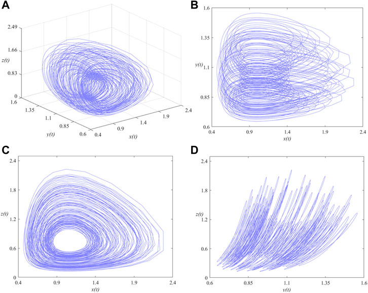
FIGURE 2. Phase portraits of the SMFrLVS when αi (i = 1, 2, 3) = 0.8 in: (A) x-y-z space, (B) x-y, (C) x-z, (D) y-z planes.
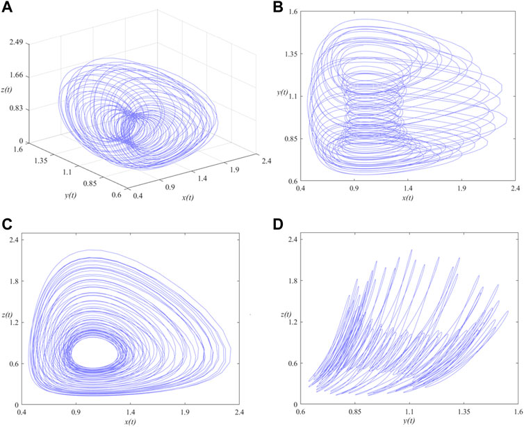
FIGURE 3. Phase portraits of the SMFrLVS when αi (i = 1, 2, 3) = 0.95 in: (A) x-y-z space, (B) x-y, (C) x-z, (D) y-z planes.
2.2.4 Multilayer short memory fractional order Lotka-Volterra system
We propose the MSMFrLVS as follows
where the parameters
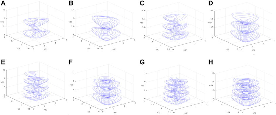
FIGURE 4. Phase portraits of the MSMFrLVS in x-y-w space and x-z-w space: (A,B):
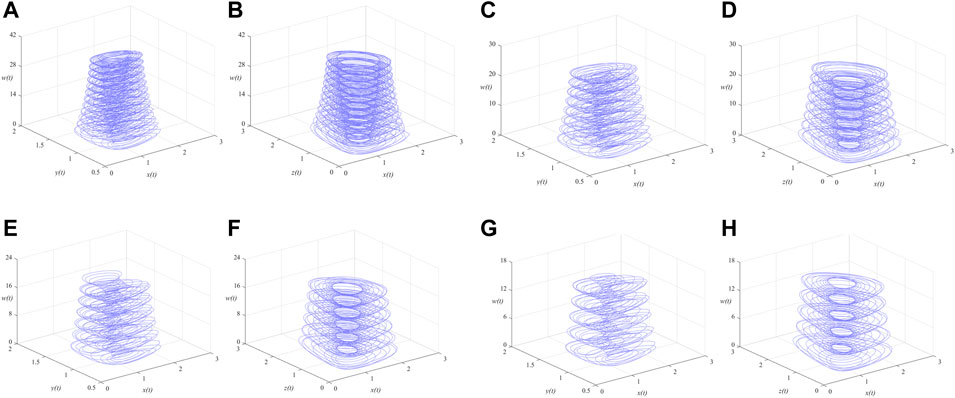
FIGURE 5. Phase portraits of the MSMFrLVS in x-y-w space and x-z-w space: (A,B):
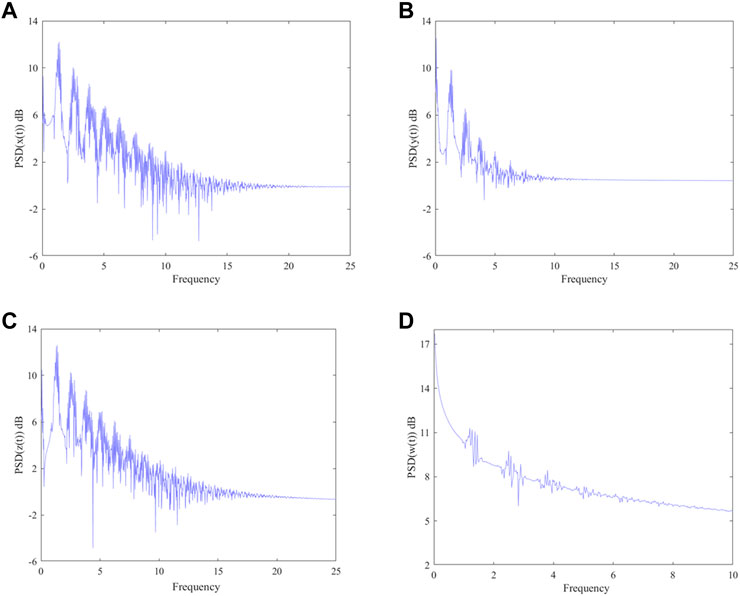
It is difficult to describe the orbits of a chaotic system concisely due to the disorder of the orbits. One of the ideas is to reduce the dimension of description and simplify the trajectory of the space into a series of discrete points, thus the Poincare section is observed. A large number of points observed at the intersection of the phase space trajectory and the Poincare section are a feature of the chaotic motion, as shown in Figure 6. In addition, the continuous frequency power spectrum is generally regarded as an indicator of chaos, the frequency power spectra of the MSMFrLVS are plotted in Figure 7.
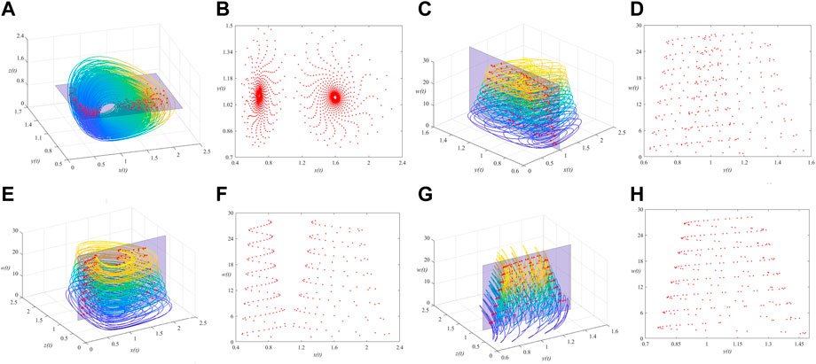
FIGURE 6. 3D view of the MSMFrLVS and the Poincare section in: (A,B): x-y-z space, (C,D): x-y-w space, (E,F): x-z-w space, (G,H): y-z-w space.
2.3 Gray code
Gray code is a signal coding method and generally used in the digital conversions [30]. Gray code can be expressed as
where
3 Quantum realization of the dual-scale triangular map
3.1 Quantum representation of the dual-scale triangular map
Li et al. [31] proposed 2D dual-scale triangular map which can be utilized to scramble a rectangle image directly. For a given
where
The inverse dual-scale triangular map is
where
According to the classical dual-scale triangular map, the quantum representation of the dual-scale triangular map can be expressed as
Correspondingly, the quantum representation of the inverse dual-scale triangular map can be defined as
3.2 Quantum circuits for the dual-scale triangular map and the inverse dual-scale triangular map
3.2.1 Quantum circuits for the dual-scale triangular map
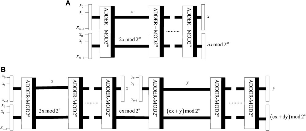
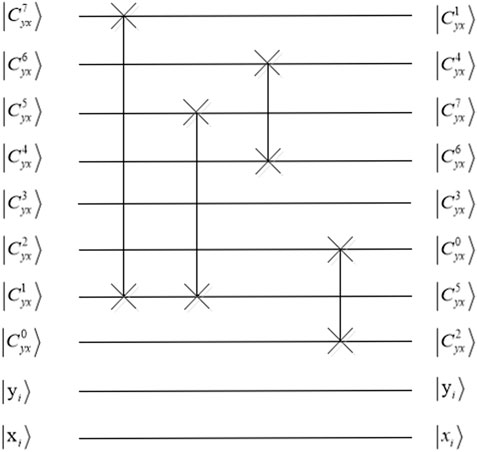
According to Eq. 17, the states
(1) Quantum circuit
(2) Quantum circuit
It shows that
3.2.2 Quantum circuits for the inverse dual-scale triangular map
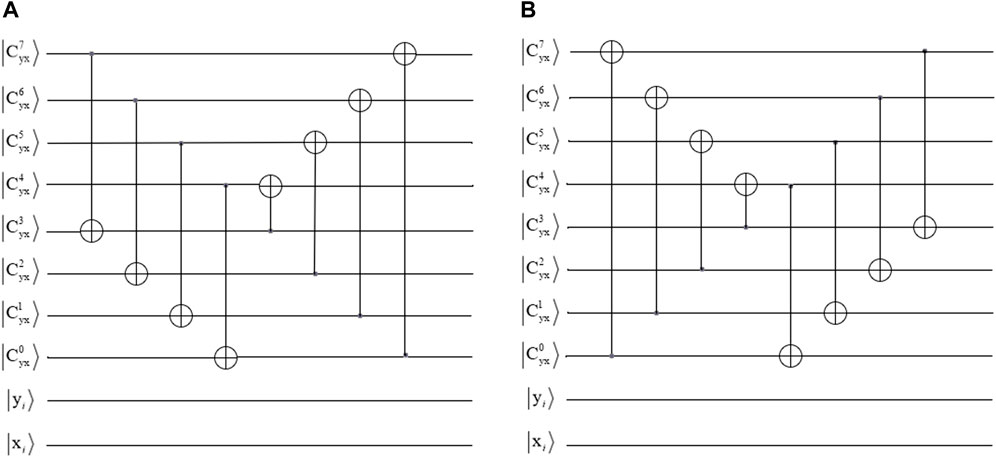
To recover the plaintext image from the scrambled image, the quantum circuits of
where
(1) Quantum circuit
(2) Quantum circuit
It demonstrates that
4 Quantum image encryption and decryption algorithm
4.1 Quantum image encryption algorithm
The proposed quantum image encryption scheme based on the MSMFrLVS and quantum dual-scale triangular map is shown in Figure 10. The plaintext image is represented with the GQIR model. During the permutation stage, the position information of the quantum image is shuffled by the block-level permutation and the intra and the inter bit-level permutation operations, while the color information of the quantum image remains unchanged. In the diffusion stage, three-level diffusion operations including pixel values, binary bits and pixel bits are accomplished for the scrambled image.
Assume the plaintext image of size
The specific encryption algorithm involves the following steps.
Step 1: Block-level scrambling is performed. To effectively realize the block-level arrangement, the plaintext image should be decomposed into sub-blocks. If the block size is
According to Eq. 17, the scrambled position qubits
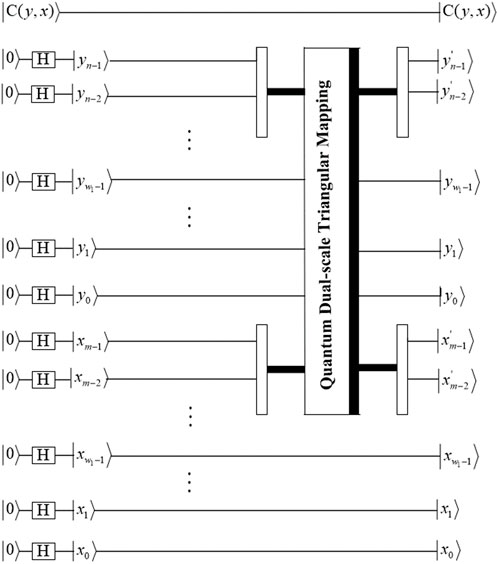
The circuit of image block-level permutation based on
Step 2. : To improve the security of the system, a plaintext correlation mechanism is employed to obtain the initial values of the MSMFrLVS. The method is expressed as
where
Step 3: The initial values
Step 4: The new chaotic sequence is transformed into integer sequence,
where
Step 5. : Bit-level permutation includes the intra bit-planes permutation and the inter bit-planes permutation. The intra bit-planes permutation is accomplished by sorting the sequence
where
By applying the quantum sub-operation
To complete bit-planes scrambling of all the pixels, a quantum operation
Step 6. : The inter bit-planes permutation is accomplished with quantum Gray code. By scrambling quantum image
Step 7. : The sequence
The scrambled quantum image
Step 8. : If
If
If
According to Eq. 36, the hundreds place
4.2 Quantum image decryption algorithm
The decryption process is the reverse process of the encryption process, the specific image decryption process is as follows.
Step 1: The encryption quantum image
Step 2. : The quantum image
Step 3: The quantum image
Step 4: The plaintext image can be recovered by performing inverse
5 Numerical simulation and discussion
The numerical simulations are run on a MATLAB R2019b platform due to a lack of equipment. To test the effectiveness and reliability of the proposed quantum image encryption algorithm, the plaintext images in Figures 14A–C are image “Barbara” of size
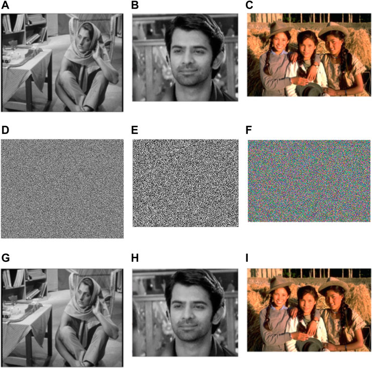
FIGURE 14. Plaintext images, ciphertext images and decryption images: (A) “Barbara,” (B) “Arnav,” (C) “Girls,” (D) “Barbara,” (E) “Arnav,” (F) “Girls,” (G) “Barbara,” (H) “Arnav,” (I) “Girls.” (“Barbara” is from the University of Southern California’s signal and image process institute image dataset, “Arnav” is from the IMDB-WIKI 500k dataset, “Girls” is from the Berkeley segmentation dataset (BSD) 500 dataset.).
The proposed algorithm was evaluated using three types of statistical property analyses, comprising histogram, correlation of adjacent pixels, and information entropy. The histogram assures that plaintext images and ciphertext images are different from each other. The association between two neighboring pixels was shown by the correlation of adjacent pixels. The information entropy looks at the encryption effect of the ciphertext images. In order to verify the proposed algorithm’s resistance to various attacks, differential attack analysis, noise attack analysis, and shear attack analysis were also carried out. To show the space and sensitivity of the keys, key space analysis and key sensitivity analysis are then done. The proposed algorithm’s computational complexity was then described. Last but not least, tests and comparisons of the encryption and decryption times in seconds were performed. All of the preceding analyses will guarantee that proposed algorithms would both be technically proficient and efficient.
5.1 Statistical property analysis
5.1.1 Histogram
The histograms of the color images “Girls,” “Sailboat,” and “Goldhill” are shown in Figures 15A–C, and the histograms of the corresponding ciphertext images are shown in Figures 15D–F. It is demonstrated that the histograms of ciphertext images differ noticeably from those of plaintext images. The pixel values of ciphertext images are evenly distributed and completely different from those of plaintext images. It demonstrates that the proposed quantum image encryption scheme can withstand the histogram attack.
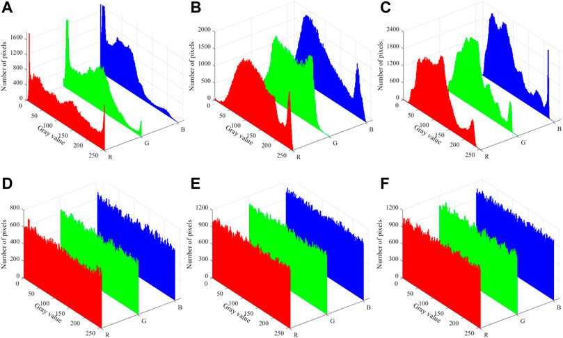
FIGURE 15. Histograms of plaintext images and ciphertext images: (A) “Girls,” (B) “Sailboat,” (C) “Goldhill,” (D) “Girls,” (E) “Sailboat,” (F) “Goldhill.”
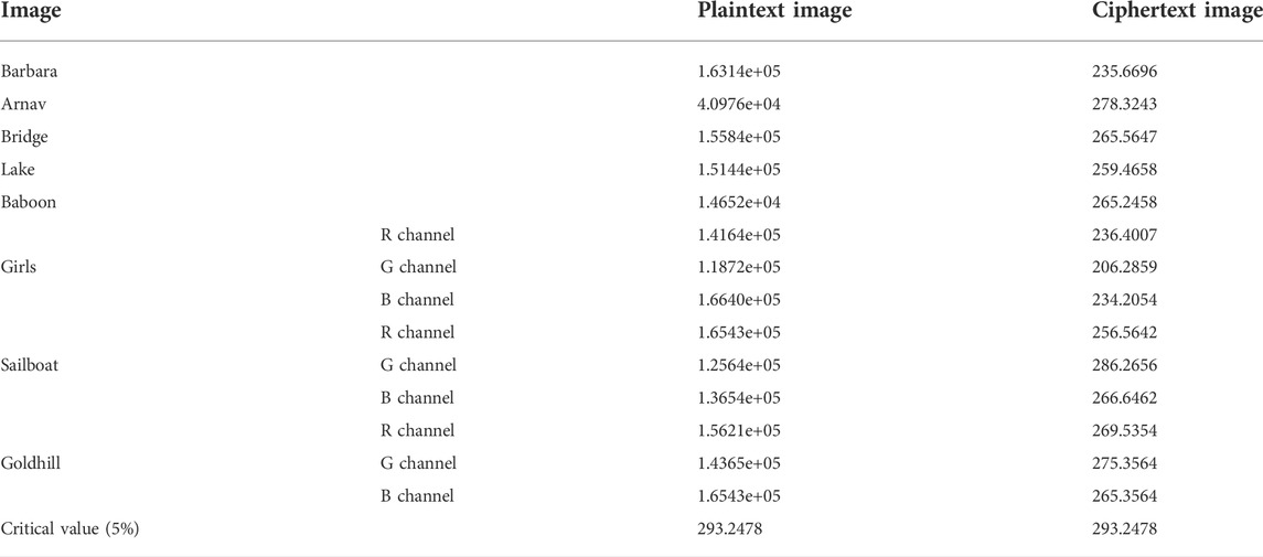
Furthermore, the chi-square test is used to precisely measure the difference between the ciphertext image and the plaintext image.
where
5.1.2 Correlation of adjacent pixels
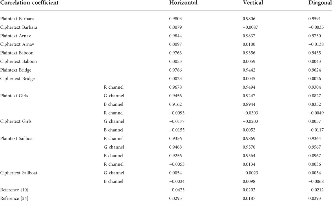
Assume that
The correlation distribution of plaintext image “Girls” and ciphertext image “Girls” in horizontal, vertical and diagonal directions are depicted in Figure 16. The correlation coefficients of plaintext images and ciphertext images are edited in Table 3. As can be seen from Figure 16 and Table 3, the correlations between the adjacent pixels of plaintext images are extremely strong, while the correlations between the adjacent pixels of ciphertext images are close to 0, which are almost no correlations. Compared with [10, 24], the proposed image encryption scheme has stronger capacity to resist the correlation analysis attack.
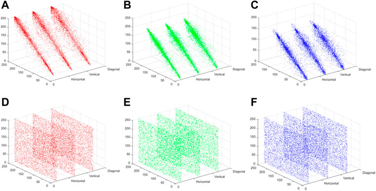
FIGURE 16. Correlation distribution of two adjacent horizontal, vertical and diagonal pixels of “Girls”: (A) R channel, (B) G channel, (C) B channel; Correlation distribution of two adjacent horizontal, vertical and diagonal pixels of encryption “Girls”: (D) R channel, (E) G channel, (F) B channel.
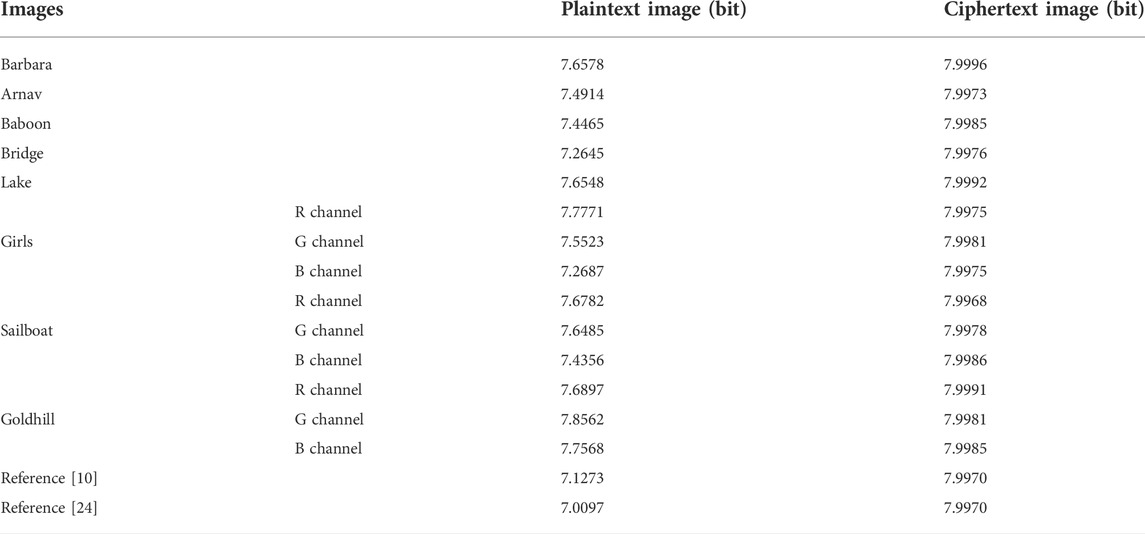
5.1.3 Information entropy
The information entropy
where
5.2 Differential attack analysis
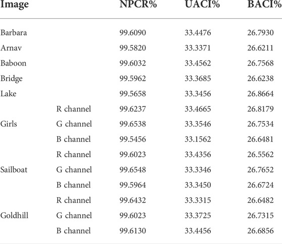
To quantitatively measure the difference between two images of the same size, Number of Pixels Change Rate (NPCR) and Unified Average Changing Intensity (UACI) can be performed.
Besides NPCR and UACI, Block Average Changing Intensity (BACI) can also measure the difference between two random images.
If the NPCR of the two images is 100%, and the UACI is close to the theoretical value, but the visual effects of the two images are similar, it indicates that NPCR and UACI are still insufficient in describing the differences between the two images, and BACI makes up for this deficiency. The theoretical value of BACI is
5.3 Key space analysis
The key space of the image cryptosystem should be large enough to resist brute force attack effectively. The key space should be at least
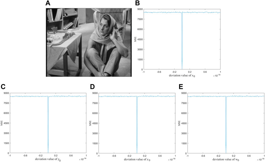
5.4 Key sensitivity analysis
A good image encryption system should have strong key sensitivity. To be more precise, the key sensitivity of the system is evaluated by the mean-squared error (MSE).
where
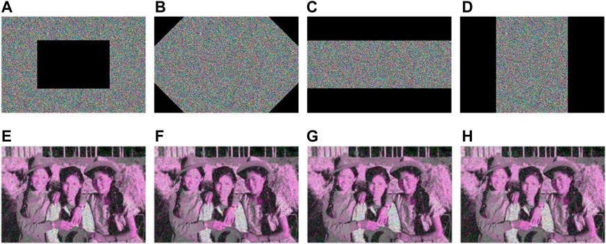
5.5 Shear attack analysis
In addition to the noise attack, the ciphertext image is also susceptible to malicious cutting by the attacker during the process of transmission and processing, therefore it is necessary to analyze the anti-clipping ability of the proposed algorithm. Figure 18 shows the ciphertext images of different clipping regions and their corresponding decryption images. From Figure 18, the resolution of decryption images varies with the cutting degree of ciphertext images, but the crucial information of the decryption images can still be identified. Therefore, the proposed encryption algorithm has a certain ability to resist the shear attack.
5.6 Computational complexity
Assume that
5.7 Noise attack analysis
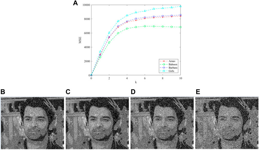
Assume that the ciphertext image “Arnav” is added with the Gaussian noise.
where
5.8 Encryption time analysis
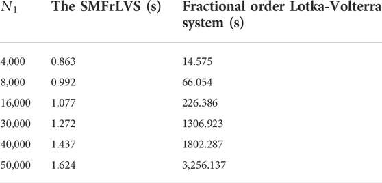
The length of the execution time is an index to evaluate the quality of an encryption algorithm. The execution time of the proposed algorithm and Refs. [9, 12, 16, 17] are listed in Table 6. In [9, 16, 17], the pseudo-random sequences are originated by iterating the 4D hyper-chaotic Henon map, 2D logistic map and 3D chaotic system, respectively, which take too much time. In [12], the encryption process is time-consuming owing to the fractional-order Lorenz-like chaotic system. In our algorithm, the initial point of the MSMFrLVS is variable such that the algorithm can save the encryption time greatly, thus the proposed image encryption algorithm can be developed for fast image encryption.
6 Conclusion
The quantum image encryption scheme is proposed by combining the MSMFrLVS with the quantum dual-scale triangular map. The block-level permutation, intra and inter bit-plane permutations, and three-level diffusion operations are used to implement the encryption process. The independent parameters of quantum dual-scale triangular map, the initial values and the control parameters of the MSMFrLVS and the hash value of plaintext image consist of the keys of the proposed quantum image encryption algorithm. As a result, the encryption system’s key space is sufficiently large. Numerical simulation analyses demonstrate the proposed algorithm’s reliability and effectiveness, and it requires less computation time. Furthermore, the proposed image encryption algorithm has lower computational complexity than its conventional counterparts. In the future, we will focus on combining quantum image encryption with semi-quantum cryptography protocols [37] in order to propose an algorithm with improved security and quantum communication capacity.
Data availability statement
The original contributions presented in the study are included in the article/supplementary material, further inquiries can be directed to the corresponding author.
Author contributions
YM: Conceptualization, methodology, investigation; F-FY: Formal analysis, writing—original draft; L-HG: Validation, writing- reviewing and editing; W-PZ: Conceptualization, funding acquisition, resources, supervision, writing—review and editing.
Funding
This work is supported by the National Natural Science Foundation of China (Grant No. 61861029), the Top Double 1000 Talent Programme of Jiangxi Province (Grant No. JXSQ2019201055).
Conflict of interest
The authors declare that the research was conducted in the absence of any commercial or financial relationships that could be construed as a potential conflict of interest.
Publisher’s note
All claims expressed in this article are solely those of the authors and do not necessarily represent those of their affiliated organizations, or those of the publisher, the editors and the reviewers. Any product that may be evaluated in this article, or claim that may be made by its manufacturer, is not guaranteed or endorsed by the publisher.
References
1. Zhou NR, Hua TX, Gong LH, Pei DJ, Liao QH. Quantum image encryption based on generalized Arnold transform and double random-phase encoding. Quan Inf Process (2015) 14(4):1193–213. doi:10.1007/s11128-015-0926-z
2. Malik A, Dhall S, Gupta S. An improved bit plane image encryption technique using RC4 and quantum chaotic demeanour. Multimed Tools Appl (2020) 80(5):7911–37. doi:10.1007/s11042-020-09973-5
3. Zhu HH, Chen XB, Yang YX. A multimode quantum image representation and its encryption scheme. Quan Inf Process (2021) 20(9):315. doi:10.1007/s11128-021-03255-1
4. Zhang JL, Huang ZJ, Li X, Wu MQ, Wang XY, Dong YM. Quantum image encryption based on quantum image decomposition. Int J Theor Phys (Dordr) (2021) 60(8):2930–42. doi:10.1007/s10773-021-04862-5
5. Wang L, Ran QW, Ma J. Double quantum color images encryption scheme based on DQRCI. Multimed Tools Appl (2020) 79(9-10):6661–87. doi:10.1007/s11042-019-08514-z
6. Vagish KD, Rajakumaran C, Kavitha R. Chaos based encryption of quantum images. Multimed Tools Appl (2020) 79(33-34):23849–60. doi:10.1007/s11042-020-09043-w
7. Zhou NR, Huang LX, Gong LH, Zeng QW. Novel quantum image compression and encryption algorithm based on DQWT and 3D hyper-chaotic Henon map. Quan Inf Process (2020) 19(9):284. doi:10.1007/s11128-020-02794-3
8. Wang Y, Chen LQ, Yu KL, Gao Y, Ma Y. An image encryption scheme based on logistic quantum chaos. Entropy (2022) 24(2):251. doi:10.3390/e24020251
9. Dai JY, Ma Y, Zhou NR. Quantum multi-image compression-encryption scheme based on quantum discrete cosine transform and 4D hyper-chaotic Henon map. Quan Inf Process (2021) 20(7):246. doi:10.1007/s11128-021-03187-w
10. Zhou NR, Chen WW, Yan XY, Wang YQ. Bit-level quantum color image encryption scheme with quantum cross-exchange operation and hyper-chaotic system. Quan Inf Process (2018) 17(6):137. doi:10.1007/s11128-018-1902-1
11. Ye GD, Jiao KX, Huang XL, Goi BM, Yap WS. An image encryption scheme based on public key cryptosystem and quantum logistic map. Sci Rep (2020) 10(1):21044. doi:10.1038/s41598-020-78127-2
12. Khan M, Rasheed A. A fast quantum image encryption algorithm based on affine transform and fractional-order Lorenz-like chaotic dynamical system. Quan Inf Process (2022) 21(4):134. doi:10.1007/s11128-022-03474-0
13. Signing VRF, Tegue GAG, Kountchou M, Njitacke ZT, Tsafack N, Nkapkop JDD, et al. A cryptosystem based on a chameleon chaotic system and dynamic DNA coding. Chaos Solitons Fractals (2022) 155:111777. doi:10.1016/j.chaos.2021.111777
14. Wang XY, Su YN, Luo C, Nian FZ, Teng L. Color image encryption algorithm based on hyperchaotic system and improved quantum revolving gate. Multimed Tools Appl (2022) 81(10):13845–65. doi:10.1007/s11042-022-12220-8
15. Li CM, Yang XZ. An image encryption algorithm based on discrete fractional wavelet transform and quantum chaos. Optik (2022) 260:169042. doi:10.1016/j.ijleo.2022.169042
16. Wu WQ, Wang Q. Quantum image encryption based on Baker map and 2D logistic map. Int J Theor Phys (Dordr) (2022) 61(3):64. doi:10.1007/s10773-022-04979-1
17. Hu WB, Dong YM. Quantum color image encryption based on a novel 3D chaotic system. J Appl Phys (2022) 131(11):114402. doi:10.1063/5.0084611
18. Kamran MI, Khan MA, Alsuhibany SA, Ghadi YY, Arshad AJ, Ahmad J, et al. A highly secured image encryption scheme using quantum walk and chaos. Comput Mater Contin (2022) 73(1):657–72. doi:10.32604/cmc.2022.028876
19. Alhumyani H, El-Banby GM, El-Sayed HS, El-Samie F, Faragallah OS. Efficient generation of cancelable face templates based on quantum image Hilbert permutation. Electronics (2022) 11(7):1040. doi:10.3390/electronics11071040
20. Zhong HY, Li GD. Multi-image encryption algorithm based on wavelet transform and 3D shuffling scrambling. Multimed Tools Appl (2022) 81:24757–76. doi:10.1007/s11042-022-12479-x
21. Chen C, Zhang HY, Wu B. Image encryption based on arnod transform and fractional chaotic. Symmetry (Basel) (2022) 14(1):174. doi:10.3390/sym14010174
22. Hu WW, Zhou RG, Luo J, Jiang SX, Luo GF. Quantum image encryption algorithm based on Arnold scrambling and wavelet transforms. Quan Inf Process (2020) 19(3):82. doi:10.1007/s11128-020-2579-9
23. Liu H, Zhao B, Huang L. Quantum image encryption scheme using Arnold transform and S-box scrambling. Entropy (2019) 21(4):343. doi:10.3390/e21040343
24. Liu XB, Xiao D, Huang W, Liu C. Quantum block image encryption based on Arnold transform and sine chaotification model. IEEE Access (2019) 7:57188–99. doi:10.1109/ACCESS.2019.2914184
25. Zhou NR, Yan XY, Liang HR, Tao XY, Li GY. Multi-image encryption scheme based on quantum 3D Arnold transform and scaled Zhongtang chaotic system. Quan Inf Process (2018) 17(12):338. doi:10.1007/s11128-018-2104-6
26. Zhou RG, Liu X, Luo J. Quantum circuit realization of the bilinear interpolation method for GQIR. Int J Theor Phys (Dordr) (2017) 56(9):2966–80. doi:10.1007/s10773-017-3463-y
27. Li Y, Chen YQ, Podlubny I. Stability of fractional-order nonlinear dynamic systems: Lyapunov direct method and generalized Mittag-Leffler stability. Comput Math Appl (2010) 59(5):1810–21. doi:10.1016/j.camwa.2009.08.019
28. Wu GC, Deng ZG, Baleanu D, Zeng DQ. New variable-order fractional chaotic systems for fast image encryption. Chaos (2019) 29(8):083103. doi:10.1063/1.5096645
29. Agrawal SK, Srivastava M, Das S. Synchronization between fractional-order ravinovich-fabrikant and lotka-volterra systems. Nonlinear Dyn (2012) 69(4):2277–88. doi:10.1007/s11071-012-0426-y
30. El-Latif AAA, Abd-El-Atty B, Talha M. Robust encryption of quantum medical images. IEEE Access (2018) 6:1073–81. doi:10.1109/ACCESS.2017.2777869
31. Li PS, Zheng Q, Hong JG, Xing CH. 2D triangular mappings and their applications in scrambling rectangle image. Inf Tech J (2008) 7(1):40–7. doi:10.3923/itj.2008.40.47
32. Jiang N, Wang L. Analysis and improvement of the quantum Arnold image scrambling. Quan Inf Process (2014) 13(7):1545–51. doi:10.1007/s11128-014-0749-3
33.University of Southern California. Signal and Image Processing Institute. USC-SIPI Image Database (1997) Available at: http://sipi.usc.edu/database (Online Accessed March 15, 2021).
34. Rothe R, Timofte R, Gool LV. Deep expectation of real and apparent age from a single image without facial landmarks. Int J Comput Vis (2018) 126(2):144–57. doi:10.1007/s11263-016-0940-3
35. Arbelaez P, Maire M, Fowlkes C, Malik J. Contour detection and hierarchical image segmentation. IEEE Trans Pattern Anal Mach Intell (2011) 33(5):898–916. doi:10.1109/TPAMI.2010161
36. Ralph TC, Resch KJ, Gilchrist A. Efficient Toffoli gates using qudits. Phys Rev A (Coll Park) (2007) 75(2):022313. doi:10.1103/PhysRevA.75.022313
Keywords: quantum image encryption, fractional order differential equation, Lotka-Volterra system, predictor-corrector method, quantum dual-scale triangular map
Citation: Ma Y, Yu F-F, Gong L-H and Zou W-P (2022) Fast quantum image encryption scheme based on multilayer short memory fractional order Lotka-Volterra system and dual-scale triangular map. Front. Phys. 10:1028630. doi: 10.3389/fphy.2022.1028630
Received: 26 August 2022; Accepted: 23 September 2022;
Published: 18 October 2022.
Edited by:
Tianyu Ye, Zhejiang Gongshang University, ChinaCopyright © 2022 Ma, Yu, Gong and Zou. This is an open-access article distributed under the terms of the Creative Commons Attribution License (CC BY). The use, distribution or reproduction in other forums is permitted, provided the original author(s) and the copyright owner(s) are credited and that the original publication in this journal is cited, in accordance with accepted academic practice. No use, distribution or reproduction is permitted which does not comply with these terms.
*Correspondence: Wei-Ping Zou, endwQG5jdS5lZHUuY24=
 Yan Ma
 Fang-Fang Yu
 Li-Hua Gong
 Wei-Ping Zou
