 Chao Yun1,2,3*†Yu Wu1,2†
 Zhongyu Liang1,2Wenyun Yang1,2
 Honglin Du1,2Shunquan Liu1,2Jingzhi Han1,2
 Yanglong Hou3,4Jinbo Yang1,2,4,5,6
 Zhaochu Luo1,2,4*
- 1State Key Laboratory of Artificial Microstructure and Mesoscopic Physics, School of Physics, Peking University, Beijing, China
- 2Institute of Condensed Matter Physics and Materials, School of Physics, Peking University, Beijing, China
- 3School of Materials Science and Engineering, Peking University, Beijing, China
- 4Beijing Key Laboratory for Magnetoelectric Materials and Devices, Beijing, China
- 5Collaborative Innovation Center of Quantum Matter, Beijing, China
- 6Peking University Yangtze Delta Institute of Optoelectronics, Nantong, China
Chiral magnetic vortex has shown great potential for high-density magnetic storage, modern telecommunication and computation devices, thanks to its topological stability and rich dynamic behaviours. Particularly, the synchronization of magnetic vortex nano-oscillators leads to the emergence of fascinating collective phenomena used for microwave generator and neuromorphic computing. In this work, by means of micromagnetic simulations, we create stable chiral magnetic vortices by exploiting the chiral coupling principle and study the gyrotropic motion of the vortex core under spin-transfer torques. The gyrotropic oscillation frequency can be tuned by injecting spin-polarised current as well as the change of the magnetic anisotropy in the vortex area, resulting from the modification of the vortex confine potential and the size of the vortex core. Two vortex nano-oscillators can be synchronized wherein the synchronization state can be modulated by the spin-polarised current and the magnetic anisotropy. Moreover, we demonstrate that the magnetic anisotropy can modify the synchronization patterns when integrating six vortices into an oscillator network, making it potentially serve as an oscillator-based neural network. Our work provides a new route to constructing a flexible oscillator network for neuromorphic computing hardware.
Introduction
Polar vortex magnetic texture has nonlinear spin swirling alignment with nontrivial topology. The unique magnetic configuration occurs as a result of the energy competition between various interactions, including magnetic exchange interaction, dipolar interaction, and importantly, the antisymmetric Dzyaloshinskii-Moriya interaction (DMI) [1–3]. The magnetic vortex, usually with nanoscale dimensions, can have superior stability thanks to the topological protection, and is less prone to defect pinning, which enables the efficient displacement with a low electric current [4]. The driving current can be as low as 106 A/m2 which is five orders of magnitude lower than the current required for domain-wall motion [5]. These properties help to realize excellent spintronic devices for high-density data storage, non-volatile logic operation and nanoscale microwave generator [6, 7]. Moreover, the particle-like characteristic of the magnetic vortex enables the potential application as magnetic synapses [8]. The local manipulation of creation, motion and deletion of magnetic vortices have been applied to mimic the potentiation and depression behaviours of biological synapses, thus showing great promises for artificial neural networks [9–11].
The magnetic vortex has rich dynamic behaviours with a broad frequency range from 0.1–100 GHz [12–14]. Response dynamics of magnetic vortices under external fields can be classified into two modes: breath mode and gyration mode. On one hand, the dynamical shrinkage/expansion of the vortex texture can be manipulated by perpendicular a. c. Magnetic field [15, 16], a. c. Current [17], or spin-orbital torques [17, 18]. On the other hand, since the inherent dynamics of magnetic vortex is gyrotropic, self-sustained magnetic oscillation can be obtained via spin transfer torques that compensate the intrinsic magnetic damping, which suggests great potential for applications in spin-torque nano-oscillators [13, 14, 19, 20]. The radio-frequency oscillation gives an electric power output in the pico-watt to nano-watt range [21, 22], which can be further enhanced by placing the nano-oscillators in arrays or networks. In such nano-oscillators, the interactions between the individual vortex nano-oscillator result in the phase locking, with all nano-oscillators oscillating in a common frequency, termed as synchronization [23]. Synchronization between magnetic nano-oscillators usually occurs as a result of exchange interactions in close proximity [24, 25], long-range dipolar coupling [14, 23, 26, 27], propagating spin waves [28] or emitted power through microwave currents [29]. The phase locking can act as an ‘anchor’ to stablise the self-sustained oscillations that is crucial for radio-frequency applications. More importantly, the nonlinear dynamics of synchronized magnetic nano-oscillators enables the development of neuromorphic computing architectures, particularly associative memories with information encoding in the individual phases of large scale arrays of interacting nano-oscillators [14]. Intercorrelated magnetic vortex oscillators provide extended possibilities to embrace the dynamical nature of the brains through interactions [14, 30–32], aiming to solve complex problems efficiently within small networks. The synchronization can also mimic the periodic spiking and synaptic communication of neurons. A coupled network of spin-torque nano-oscillators can learn to perform computational tasks through synchronization, for applications in speech, pattern recognition, where each synchronization pattern can be used directly as an output for the neural networks [31, 33]. Therefore, finding an efficient way to manipulate the synchronization is crucial for magnetic vortex oscillator-based neuromorphic computing devices.
The nonlinear dynamics of magnetic vortex oscillators results in easy adaption of their frequencies to the external stimuli or other associative oscillators. The modified dynamics of individual oscillator can in turn influence the synchronization [14], and hence large varieties of synchronization patterns can be obtained when different external stimuli are implemented. Indeed, magnetic field and spin-polarised current have been reported to successfully tune the dynamic properties of magnetic vortex nano-oscillators [19, 20, 34, 35]. Since the oscillation frequency depends on the vortex potential energy, the magnetic anisotropy of the vortex region, which directly influences the magnetic anisotropy energy, can provide a new route to modulating the oscillation dynamics. In experiment, the magnetic anisotropy can be readily modified via voltage controlled perpendicular magnetic anisotropy (VCMA) effect [36–39].
In this work, using micromagnetic simulation, we introduce magnetic anisotropy as a degree of freedom to manipulate the oscillation dynamics and the synchronization of magnetic vortices. The vortex structure for a single oscillator is generated through chiral coupling principle between adjacent regions with in-plane (IP) and out-of-plane (OOP) anisotropy inside a magnetic vortex, and is stabilised via interfacial DMI. Although magnetic vortex can be formed and the oscillation and synchronization phenomena can be realized without DMI [12, 34, 40, 41], the presence of DMI, on the other hand, has been reported to obtain a large frequency and can protect the magnetic texture of the magnetic vortex under a large spin current, thus making the vortex more stable and favouring the development of microwave signal generator [42]. Also, DMI can help to realize small magnetic nano-oscillators (as small as 10 nm) [43, 44]. The DMI-stabilised chirally coupled nanomagnets have been experimentally demonstrated to realize current-driven domain-wall logic, synthetic antiferromagnets and Ising-like artificial spin ices [45–48]. Here, by altering the magnetic anisotropy of the vortex region from IP to OOP, i.e. by increasing the value of magnetic anisotropy constant, we show that the oscillation frequency of a magnetic vortex increases significantly. This magnetic anisotropy-dependence of the oscillation dynamics can be used to modulate the synchronization of two vortex oscillators, based on which we design an oscillator network which is capable of programming synchronization configurations used for pattern recognition. As compared to the spin-current-based vortex oscillator reported previously, here magnetic anisotropy is introduced as a new degree of freedom to tune the dynamics, and the mechanism for dynamics modulation is explained in a more comprehensive way. Moreover, the spin current and the magnetic anisotropy can be combined to tune the synchronization configuration and potentially provide extended flexibility for neuromorphic computing.
Methods
To study the oscillation dynamics of the magnetic vortex, micromagnetic simulations were carried out with the MuMa×3 code [49] using a computation box with 2 × 2 × 1 nm3 discretization. The MuMax3 utilises the Landau– Lifshitz–Gilbert–Slonczewski (LLG) equation as the basic formalism for describing the low-energy magnetisation dynamics (for details, see Appendix A). The magnetic parameters are taken from the experimentally reported chirally coupled nanomagnet based on Pt/Co/AlOx multilayer, with a saturation magnetisation MS = 1.0 MA/m, exchange constant A = 16 pJ/m, interfacial DMI constant D = −1.5 mJ/m−2 favouring left-handed chirality, uniaxial anisotropy constant of the OOP region K0 = 7.03 × 10⁵ J/m2, and Gilbert damping constant α = 0.01. A circular region with a diameter of 100 nm (named as vortex region hereafter) is embedded inside the computation box with a fixed OOP magnetic anisotropy (named as OOP region hereafter) to form the vortex-like magnetic texture. To reach the vortex-like magnetic texture, the magnetisation in the OOP region is set to the +z direction, while the magnetisation in the vortex region is set to its opposite direction, after which the system is relaxed. Self-sustained oscillation of the vortex core is then obtained by injecting a spin polarised current along the +z direction in the vortex region. The x component of the average magnetisation (MVx) in the vortex region, which is closely correlated to the oscillation of the core, is used to illustrate the dynamic behaviour of the vortex [50]. The oscillation frequency is obtained from the frequency spectra converted via fast Fourier transformation (FFT) on the time-dependent MVx with the simulation running over a period of 150 ns. To study the influence of anisotropy on the oscillation frequency, the magnetic anisotropy constant of the vortex region is varied from 0. To study the synchronization phenomena. Several vortices are separated with each other by a certain distance to create a network. The synchronization spectra are obtained by superimposing the frequency spectra of each single vortex. When mutual phase-locking occurs, the spectra exhibit a strengthened intensity with a common shared peak, otherwise separated peaks with much weaker intensities are observed. All the simulations are performed at zero absolute temperature without considering the thermal magnetisation fluctuations.
Results and discussions
Single oscillator
We first consider the dynamics of a single vortex. As shown in Figure 1, a circular region with variable magnetic anisotropy (vortex region) is embedded in a slab with a fixed uniaxial OOP anisotropy (OOP region). When the uniaxial magnetic anisotropy constant of the vortex region (KV) is initially set to be 0, the vortex region has an IP anisotropy, and the chiral vortex magnetic texture is stabilised by the interfacial DMI: HDM = –Dij · (mi × mj) where Dij denotes the DMI vector of interfacial-type DMI, and the DMI energy is given by
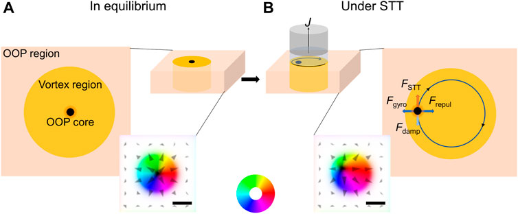
FIGURE 1. Schematic illustration of a magnetic vortex structure where circular vortex regions with tunable anisotropy are surrounded by regions with fixed out-of-plane (OOP) anisotropy and a core with out-of-plane magnetisation is induced: (A) in equilibrium and (B) in oscillation under spin-polarised current. The insets show the magnetisation configuration of the simulated area. Magnetisation along the +z and–z direction is indicated in white and black, while the magnetisation direction in the vortex region is given by the colour wheel. Scale bar: 50 nm.
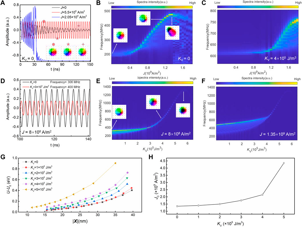
FIGURE 2. (A) Oscillation amplitudes of x component of average magnetisation in the vortex when the spin polarised current J = 0 (black), J = 5.5 × 10⁸ A/m2 (red) and J = 2.05 × 10⁹ A/m2 (blue). Dependence of oscillation frequency on J for (B) the anisotropy constant of vortex region KV = 0 and (C) KV = 4 × 10⁵ J/m3. (D) Oscillation amplitudes of x component of average magnetisation in the vortex region when KV = 0 (black) and KV = 3 × 10⁵ J/m3 (red) for J = 8 × 10⁸ A/m2. Dependence of oscillation frequency on KV for (E) J = 8 × 10⁸ A/m2 and (F) J = 1.35 × 10⁹ A/m2. (G) Dependence of the potential energy (U) on the variation of the core displacement (|X|) at different KV values. (H) The change of upper limit current density (JC) for the self-sustained oscillation with the change in KV.
Note that the required STT current density (108–109 A/m2) is much lower than the spin-orbital-torque (SOT) current density (1011 A/m2) in a similar structure [57] which is due to the following reasons: First, the charge-to-spin conversion efficiency in the STT (around 0.5 in Pt/Co system [52]) is usually higher as compared to SOT (around 0.1 in Pt [53]). Second, the spin current drives a gyrotropic motion of magnetic oscillator around the equilibrium spin texture, while the SOT switching needs to overcome the magnetic anisotropy and rotate the magnetisation for 180°. So the oscillation spin current density is lower than that for switching the magnetisation. Meanwhile, we have not considered the pinning effect which may increases the required spin current density in the real devices.
To study the influence of magnetic anisotropy on the dynamic behaviour of a single vortex, we fix the electric current J = 8.0 × 10⁸ A/m2 and vary the magnetic anisotropy constant KV from 0. When KV is equal to 0, due to chiral coupling the vortex region forms a stable skyrmion-like spin texture with a small OOP core (left inset of Figure 2E) as a result of exchange singularity [23, 50]. The self-sustained oscillation, as shown in Figure 2D (curve in black for KV = 0), has a constant amplitude with a fixed period of 32.6 ns, corresponding to a frequency of 306 MHz. With the increase of KV, the oscillation frequency first increases slowly when KV <3 × 10⁵ J/m3, and then increases drastically when KV >3 × 10⁵ J/m3 (Figure 2E). Meanwhile, the size of the vortex core, as shown in the middle and right inset of Figure 2E (for KV = 4 × 10⁵ J/m3), undergoes a significant expansion. The red oscillation curve in Figure 2D (representing the oscillation at KV = 3 × 10⁵ J/m3), as compared to the black curve (KV = 0) has a shorter oscillation period (25 ns) with a larger frequency (400 MHz). The oscillation amplitude, which is proportional to the average magnetisation of the vortex region, also decreases, due to the expansion of the core region and the reduction of the IP magnetised region. Interestingly, when KV is beyond a critical point of ∼5.8 × 10⁵ J/m3, the spectra intensity gradually vanishes, indicating the breakdown of the self-sustained oscillation. As shown in the right inset of Figure 2E, the size of OOP core enlarges to be almost equal to the vortex region when KV = 5.8 × 10⁵ J/m3, resulting in the annihilation of the vortex structure. A similar phenomenon is observed when J is increased to 13.5 × 10⁸ A/m2 (Figure 2F), where the frequency increases less rapidly with the increasing of KV, with a peak reaching at a similar KV = 5.8 × 10⁵ J/m3 before the vortex structure collapses. The annihilation of the vortex structure due to the modification of magnetic anisotropy has been realized experimentally through VCMA effects [36, 37, 58, 59], where a well-defined IP anisotropy in the radial vortex region is crucial for maintaining the noncolinear spin texture of vortex structure through DMI. When KV increases, the antisymmetric DMI is gradually taken over by the symmetric exchange interaction, while the latter favours a colinear and parallel spin alignment between adjacent regions, which eventually results in the collapse of the noncolinear vortex spin texture.
To further understand the tunable dynamic behaviour of the vortex oscillation under the influence of J and KV, we refer to the centre-of-mass dynamics of the magnetic vortex oscillator, which has been well-modelled by the single collective variable Thiele equation [60–62].
The first term represents the gyrotropic force (also termed as Magnus force), where
We first consider the role of spin polarised current J. As discussed above, the confining potential provides an inward radial repulsive force (second term in Eq. 1) to confine the vortex inside the vortex region, while the spin transfer torque (STT force, the last term in Eq. (1)) arising from J tends to drive the core outward toward the edge, so does the gyrotropic force (first term in Eq. (1)). With the increase in J, the radius of the steady state orbit increases (as shown in the middle inset of Figure 2B in comparison with the left inset), as a larger dissipation rate is required to compensate the increase in spin torques [50]. The gyrotropc force increases as well to counterbalance the increase in the STT force, resulting in the increase in the velocity of the core
We now turn to understand the role of KV on the oscillation dynamics. The intrinsic oscillation frequency is determined by the curvature of the confining potential at the equilibrium core position in the absence of STT force [50]. We first calculate the relative potential energy of system (U-U0, where U0 is the potential energy when the core is in the centre) with respect to different core distances from the centre (|X|) at different KV values in the absence of STT (Figure 2G). Since the equilibrium position of the core is in the centre, U-U0 increases when the core displaces away from the centre. Interestingly, when KV increases, U-U0 increases more rapidly with displacement, especially at large KV values, indicating that the potential energy becomes higher when the core has the same displacement. This, on one hand, directly increases the slope of the curve as observed in Figure 2G, corresponding to an enhanced
The potential energy is closely correlated to the evolution of the vortex structure. As mentioned above, the vortex core expands rapidly when KV increases (insets in Figure 2E), which leads to the shrinkage of the noncolinear spin region. The enlarged OOP core and the reduced vortex area make it more difficult for the core to move, and thus a higher exchange energy is needed, which results in the increase in the overall potential energy and the oscillation frequency. Hence, the tuning of the oscillation frequency by KV is understood.
Synchronization of two oscillators
We next turn to investigate how the spin current and magnetic anisotropy affect the mutual interactions for a couple of oscillators. In the simulation, two vortex oscillators are placed with a given distance, while the J and KV are varied (Figure 3A). As mentioned earlier, interacting non-identical oscillators with different intrinsic frequencies tend to undergo resonance at a common frequency when their oscillation frequencies are within an certain locking range, resulting in the synchronization phenomena [23, 50]. Figure 3B shows the synchronization spectra as a function of the current density for a pair of oscillators (named as one and 2) with a 100 nm distance when KV = 0. When the spin polarised current of oscillator 1 (J1) is fixed at 8 × 10⁸ A/m2 and that of oscillator 2 (J2) varies from 0 to 1.25 × 10⁹ A/m2, two distinct frequency peaks are observed at small J2, and then they merge into one peak with an enhanced intensity, undergoing synchronization when J2 ranges between 6 × 10⁸ A/m2 and 1 × 10⁹ A/m2. The merged peak diverge again when J2 > 1 × 10⁹ A/m2. In order to study the influence of magnetic anisotropy on the synchronization, the magnetic anisotropy constant in the vortex region of oscillator 1 (KV1) is fixed at 1 × 10⁵ J/m3 while that of oscillator (KV2) varies from 0 to 3 × 10⁵ J/m3. We first study the case where different currents are injected into the two oscillators: J1 (8 × 10⁸ A/m2) ≠ J2 (6.5 × 10⁸ A/m2). As shown in Figure 3C, the two oscillators synchronize with each other when KV2 ranges from 6 × 10⁴ J/m3 to 1.5 × 10⁵ J/m3. The synchronized region ΔKV2, defined as the length of the interval between the starting and ending point of KV2 of the synchronization region, is estimated to be 0.9 × 10⁵ J/m3. It is noteworthy that the frequency spectra and synchronization region keep unchanged when the two different oscillators swap their relative positions, as shown in Figure 3D, indicating that the contributions from two oscillators are switchable with regard to position.
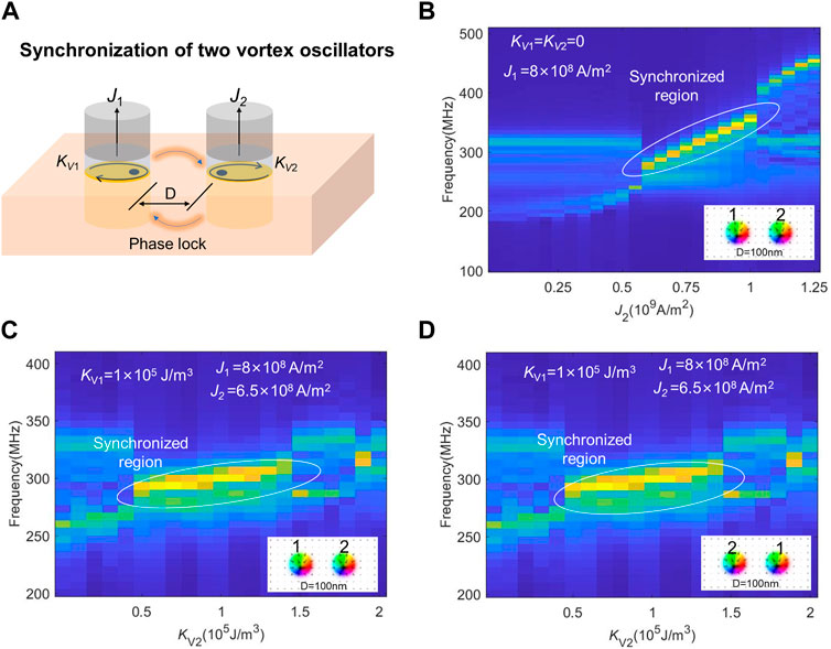
FIGURE 3. (A) Schematic illustration for the synchronization of two non-identical vortex nano-oscillators with varying spin polarised current density (J) and anisotropy constant of the vortex region (KV). (B) Synchronization frequency spectra for two oscillators separated by a distance of 100 nm with varying J when the KV for both oscillators are 0. The injected current density for oscillator 1 (J1) is fixed at 8 × 10⁸ A/m2 while that of oscillator 2 (J2) is varied. (C) Synchronization frequency spectra for two oscillators separated by a distance of 100 nm with varying KV when the J for both oscillators are fixed at 8 × 10⁸ A/m2. The anisotropy constant of the vortex region for oscillator 1 (KV1) is fixed at 1 × 10⁵ J/m3 while that of oscillator 2 (KV2) is varied. (D) Synchronization frequency spectra when oscillator one and two switch their positions.
The synchronization of nano-oscillators in this system can be realized through propagating spin waves or dipolar interactions [14], where the distance between the oscillators plays a crucial role to determine the synchronization stability and coupling strength [50]. Here, to better understand the distance effect, the separation between the oscillators is varied from 60 to 150 nm. Figures 4A–C show the synchronization spectra with a distance of 60, 80 and 100 nm, respectively, for J1 (8 × 10⁸ A/m2) ≠ J2 (6.5 × 10⁸ A/m2) (termed as ‘nonequal case’) and Figures 4D–F show the respective spectra for J1 (8 × 10⁸ A/m2) = J2 (8 × 10⁸ A/m2) (termed as ‘equal case’). In both cases, the synchronization range ΔKV2 decreases with the increase in separation distance (Figure 4G), which could be attributed to the decay in coupling strength [50]. Interestingly, the decrease in ΔKV2 for the nonequal case is much more rapid than the equal case: at a small distance of 60 nm, ΔKV2 of the nonequal case is similar to that of the equal case, both having a large synchronization interval of ∼3 × 10⁵ J/m3; in contrast, when the distance increases to 150 nm, ΔKV2 for the equal case keeps at a sizable value 1.7 × 10⁵ J/m3, while for the nonequal case it decays to 0.1 × 10⁵ J/m3. This stark difference is a clear indication of the faster decay for the overall strength of oscillator interaction with the increase in separation distance when the two current densities are different, which could be due to the relative contribution from different source of interaction (dipolar interaction or spin wave propagation) changes when the current density and distance are different.
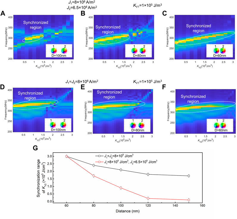
FIGURE 4. (A–C) Influence of oscillator distance on the synchronization frequency spectra for two oscillators with varying anisotropy (KV) when the current density (J) for the two oscillators are nonequal (J1 = 8 × 10⁸ A/m2 and J2 = 6.5 × 10⁸ A/m2): (A) D = 100 nm (B) D = 80 nm and (C) D = 60 nm. The anisotropy constant of the vortex region for oscillator 1 (KV1) is fixed at 1 × 10⁵ J/m3 while that of oscillator 2 (KV2) is varied. (D–F) Influence of oscillator distance on the synchronization frequency spectra for two oscillators with varying anisotropy (KV) when the current density (J) for both oscillators are equal (J1 = J2 = 8 × 10⁸ A/m2): (A) D = 100 nm (B) D = 80 nm and (C) D = 60 nm. The anisotropy constant of the vortex region for oscillator 1 (KV1) is fixed at 1 × 10⁵ J/m3 while that of oscillator 2 (KV2) is varied. (G) The change of synchronization range with varying the distance of the two oscillators. The error bar is taken as the interval of the variation of the anisotropy constant in the simulation.
Synchronization of multiple oscillators for neural networks
The synchronization of nano-oscillators is of great interest for neuromorphic computing. As a proof-of-concept demonstration, we design a neural network comprised of six vortex oscillators (A, B and 1, 2, 3, 4) (Figure 5A), and explore the ability of coupled vortex nano-oscillators to work as a model system for neuromorphic computing via anisotropy control. Figure 5B shows the schematic for the intercorrelation between oscillators, neurons, inputs and outputs. The oscillators are separated from each other with a certain distance, with 1–4 (output neurons) surrounded by A and B (input oscillators), so that all oscillators can be mutually interacted with each other. As shown below, the change in KV of the two input oscillators can modify the synchronization configurations of the whole neural network, mimicking the conversion of encoded inputs to classified output signals via programmable weighting mechanism [30]. Hence, the synchronization configuration between the six oscillators is interpreted here as the output signal.
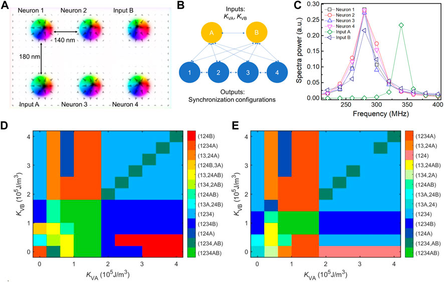
FIGURE 5. (A) Configuration of the neural network with two input oscillators (A,B) and four neuron oscillators (1,2,3,4). (B) Schematic illustration for the intercorrelation between the oscillators, neurons, inputs and outputs. (C) The output frequencies of the oscillators, for the case of KVA = 2.4 × 10⁵ J/m3, KVB = 1.6 × 10⁵ J/m3. J and for all the oscillators are fixed at 8 × 10⁸ A/m2, and KV for neurons 1,2,3,4 are 1.1 × 10⁵ J/m3, 0.8 × 10⁵ J/m3, 1.2 × 10⁵ J/m3, 0.9 × 10⁵ J/m3, respectively. (D) 2D synchronization map with varying KVA and KVB when JB = 8 × 10⁸ A/m2. (E) 2D synchronization map with varying KVA and KVB when JB = 9 × 10⁸ A/m2.
To begin with, we set up one input signal using the magnetic anisotropy of either oscillator A or B (KVA or KVB), and then increase to two input signals by adopting both KVA and KVB. The current density J for all the oscillators is set to be 8 × 10⁸ A/m2, and the KV for the output neurons 1, 2, 3, and four are set to be 1.1 × 10⁵ J/m3, 0.8 × 10⁵ J/m3, 1.2 × 10⁵ J/m3, 0.9 × 10⁵ J/m3, respectively. When KVA and KVB are varied from 0 to 4 × 10⁵ J/m3, the frequency patterns of the neural network are converged and allocated to different synchronization configurations appearing at different KVA and KVB values. For example, when KVA = 2.4 × 10⁵ J/m3 and KVB = 1.6 × 10⁵ J/m3, five oscillators (1, 2, 3, 4 and B) are synchronized into one common frequency (Figure 5C) during a running period of 50 ns, corresponding to an output synchronization code of (1234B). A total of 13 output patterns are obtained, as represented by 13 different colours organised into a two-dimensional colour map (Figure 5D), while only up to six configurations can be recognised with one input (either KVA or KVB). Interestingly, when JB changes to 9 × 10⁸ A/m2, the synchronization pattern is modified (Figure 5E): the synchronization codes (124B), (134, 2AB) and (124B, 3A) that appear in the case of JB = 8 × 10⁸ A/m2 now disappear, while another three codes (13A, 24), (134, 2A) and (124) emerge. This indicates that current can work jointly with the magnetic anisotropy to modulate the output synchronization patterns.
In the proof-of-concept neural network shown in Figure 5, we have six oscillators, each having independent current density and magnetic anisotropy. The neural network hence has twelve variables. Two variables (KVA and KVB) can act as inputs and tune the synchronization patterns as the outputs (Figure 5D). We also found that the synchronization pattern changes when the current density of one oscillator is changed (Figures 5E vs 5D), indicating that the output depends on the combination of all variables. When two variables (KVA, KVB) are defined as the inputs, the combination of the rest ten variables (KV1 … KV4, J1, … , J4 and JA, JB) can be defined as the weight and bias. When these ten parameters are changed, the weight and bias are changed, resulting in a different output pattern (as shown in Figures 5D,E). Therefore, we can train the neural network to get a target output pattern by adjusting the weight and bias parameters via a learning rule.
Conclusion
We propose a spintronic nano-oscillator based on the tunable magnetic anisotropy of a polar vortex magnetic structure. The increase of the magnetic anisotropy in the vortex region, which modifies the confine potential and the topology of the magnetic vortex texture, brings the oscillation frequency to higher values and increase the upper critical limit of the spin-polarised currents. The change in oscillation frequency can modify the synchronization between a pair of oscillators. Making use of the tunable dynamics, we show that a designed network of tunable magnetic vortex oscillators can serve as a model system for neuromorphic computing, which is capable to recognise different output synchronization configurations when the magnetic anisotropies of vortices are encoded as inputs. We also found that the output patterns are modified when the spin-polarised current changes. Since both the magnetic anisotropy and spin-polarised current can be experimentally tuned, our model system possesses great potential as a hardware for neuromorphic computing with large flexibility.
Data availability statement
The data presented in the study are deposited in the Zendo repository, accession number: https://zenodo.org/deposit/7149131.
Author contributions
ZLu and CY conceived and designed the project. CY, ZLi, and ZLu performed the simulation. CY and YW analysed the simulation data. CY and ZLu worked on the manuscript. All authors are contributed to the discussion on the data and revision of the manuscript.
Acknowledgments
The authors acknowledge funding from the National Natural Science Foundation of China (Grant Nos. 51731001, 52201287, 52271160, 11975035, 11805006, 11675006, 52027801, 52111530236), the National Key Research and Development Program of China (Grant No. 2021YFB3500300) and the China-Germany Collaboration Project (M-0199). CY acknowledges the funding from Boya postdoctoral fellowship, Peking University for support of the research.
Conflict of interest
The authors declare that the research was conducted in the absence of any commercial or financial relationships that could be construed as a potential conflict of interest.
Publisher’s note
All claims expressed in this article are solely those of the authors and do not necessarily represent those of their affiliated organizations, or those of the publisher, the editors and the reviewers. Any product that may be evaluated in this article, or claim that may be made by its manufacturer, is not guaranteed or endorsed by the publisher.
Appendix A: Basic formalism of the Mumax software
The MuMax3 code is based on the low-energy magnetisation dynamics in strong ferromagnets, which is well-described by the Landau–Lifshitz–Gilbert–Slonczewski (LLG) equation [65, 66]
where m =
where U is the free energy of the system.
where D is the DMI constant and mx, my, mz are the components of the normalized magnetization vector m. The second term on the right is the Gilbert term representing viscous damping, where α is the Gilbert damping constant. The third term on the right hand is the Slonczewski term describing the torque arising from the coupling between the local magnetisation and the spin-polarised current flowing perpendicular to the film plane.
References
1. Mühlbauer S, Binz B, Jonietz F, Pfleiderer C, Rosch A, Neubauer A, et al. Skyrmion lattice in a chiral magnet. Science (80) (2009) 323:915–9. doi:10.1126/science.1166767
2. Yu XZ, Onose Y, Kanazawa N, Park JH, Han JH, Matsui Y, et al. Real-space observation of a two-dimensional skyrmion crystal. Nature (2010) 465:901–4. doi:10.1038/nature09124
3. Malozemoff A, Slonczewski J. Magnetic domain walls in bubble materials. New York: Academic Press (1979). doi:10.1016/C2013-0-06998-8
4. Karakas V, Gokce A, Habiboglu AT, Arpaci S, Ozbozduman K, Cinar I, et al. Observation of magnetic radial vortex nucleation in a multilayer stack with tunable anisotropy. Sci Rep (2018) 8:7180. doi:10.1038/s41598-018-25392-x
5. Guo JH, Xia J, Zhang X, Pong PWT, Zhou Y. A ferromagnetic skyrmion-based nano-oscillator with modified perpendicular magnetic anisotropy. Phys Lett A (2021) 392:127157. doi:10.1016/j.physleta.2021.127157
6. Tokura Y, Kanazawa N. Magnetic skyrmion materials. Chem Rev (2021) 121:2857–97. doi:10.1021/acs.chemrev.0c00297
7. Fert A, Cros V, Sampaio J. Skyrmions on the track. Nat Nanotechnol (2013) 8:152–6. doi:10.1038/nnano.2013.29
8. Nagaosa N, Tokura Y. Topological properties and dynamics of magnetic skyrmions. Nat Nanotechnol (2013) 8:899–911. doi:10.1038/nnano.2013.243
9. Song KM, Jeong J-S, Pan B, Zhang X, Xia J, Cha S, et al. Skyrmion-based artificial synapses for neuromorphic computing. Nat Electron (2020) 3:148–55. doi:10.1038/s41928-020-0385-0
10. Li S, Kang W, Huang Y, Zhang X, Zhou Y, Zhao W. Magnetic skyrmion-based artificial neuron device. Nanotechnology (2017) 28:31LT01. doi:10.1088/1361-6528/aa7af5
11. Yu Z, Shen M, Zeng Z, Liang S, Liu Y, Chen M, et al. Voltage-controlled skyrmion-based nanodevices for neuromorphic computing using a synthetic antiferromagnet. Nanoscale Adv (2020) 2:1309–17. doi:10.1039/D0NA00009D
12. Choe S-B, Acremann Y, Scholl A, Bauer A, Doran A, Stöhr J, et al. Vortex core-driven magnetization dynamics. Science (80) (2004) 304:420–2. doi:10.1126/science.1095068
13. Garcia-Sanchez F, Sampaio J, Reyren N, Cros V, Kim J. A skyrmion-based spin-torque nano-oscillator. New J Phys (2016) 18:075011. doi:10.1088/1367-2630/18/7/075011
14. Locatelli N, Hamadeh A, Abreu Araujo F, Belanovsky AD, Skirdkov PN, Lebrun R, et al. Efficient synchronization of dipolarly coupled vortex-based spin transfer nano-oscillators. Sci Rep (2015) 5:17039. doi:10.1038/srep17039
15. Mochizuki M. Spin-wave modes and their intense excitation effects in skyrmion crystals. Phys Rev Lett (2012) 108:017601. doi:10.1103/PhysRevLett.108.017601
16. Moon K-W, Kim D-H, Je S-G, Chun BS, Kim W, Qiu ZQ, et al. Skyrmion motion driven by oscillating magnetic field. Sci Rep (2016) 6:20360. doi:10.1038/srep20360
17. Litzius K, Lemesh I, Krüger B, Bassirian P, Caretta L, Richter K, et al. Skyrmion Hall effect revealed by direct time-resolved X-ray microscopy. Nat Phys (2017) 13:170–5. doi:10.1038/nphys4000
18. Woo S, Song KM, Han H-S, Jung M-S, Im M-Y, Lee K-S, et al. Spin-orbit torque-driven skyrmion dynamics revealed by time-resolved X-ray microscopy. Nat Commun (2017) 8:15573. doi:10.1038/ncomms15573
19. Demidov VE, Urazhdin S, Ulrichs H, Tiberkevich V, Slavin A, Baither D, et al. Magnetic nano-oscillator driven by pure spin current. Nat Mater (2012) 11:1028–31. doi:10.1038/nmat3459
20. Saha S, Flauger P, Abert C, Hrabec A, Luo Z, Zhou J, et al. Control of damping in perpendicularly magnetized thin films using spin-orbit torques. Phys Rev B (2020) 101:224401. doi:10.1103/PhysRevB.101.224401
21. Abreu Araujo F, Darques M, Zvezdin KA, Khvalkovskiy AV, Locatelli N, Bouzehouane K, et al. Microwave signal emission in spin-torque vortex oscillators in metallic nanowires: Experimental measurements and micromagnetic numerical study. Phys Rev B (2012) 86:064424. doi:10.1103/PhysRevB.86.064424
22. Kumar D, Barman S, Barman A. Magnetic vortex based transistor operations. Sci Rep (2015) 4:4108. doi:10.1038/srep04108
23. Zaspel CE. Synchronization in alternating linear chains of vortex-based spin-torque oscillators. J Magn Magn Mater (2019) 492:165683. doi:10.1016/j.jmmm.2019.165683
24. Mancoff FB, Rizzo ND, Engel BN, Tehrani S. Phase-locking in double-point-contact spin-transfer devices. Nature (2005) 437:393–5. doi:10.1038/nature04036
25. Ruotolo A, Cros V, Georges B, Dussaux A, Grollier J, Deranlot C, et al. Phase-locking of magnetic vortices mediated by antivortices. Nat Nanotechnol (2009) 4:528–32. doi:10.1038/nnano.2009.143
26. Slavin AN, Tiberkevich VS. Nonlinear self-phase-locking effect in an array of current-driven magnetic nanocontacts. Phys Rev B (2005) 72:092407. doi:10.1103/PhysRevB.72.092407
27. Hrabec A, Křižáková V, Pizzini S, Sampaio J, Thiaville A, Rohart S, et al. Velocity enhancement by synchronization of magnetic domain walls. Phys Rev Lett (2018) 120:227204. doi:10.1103/PhysRevLett.120.227204
28. Kaka S, Pufall MR, Rippard WH, Silva TJ, Russek SE, Katine JA. Mutual phase-locking of microwave spin torque nano-oscillators. Nature (2005) 437:389–92. doi:10.1038/nature04035
29. Grollier J, Cros V, Fert A. Synchronization of spin-transfer oscillators driven by stimulated microwave currents. Phys Rev B (2006) 73:060409. doi:10.1103/PhysRevB.73.060409
30. Martins L, Jenkins AS, Alvarez LSE, Borme J, Böhnert T, Ventura J, et al. Non-volatile artificial synapse based on a vortex nano-oscillator. Sci Rep (2021) 11:16094. doi:10.1038/s41598-021-95569-4
31. Nikonov DE, Csaba G, Porod W, Shibata T, Voils D, Hammerstrom D, et al. Coupled-oscillator associative memory array operation for pattern recognition. IEEE J Explor Solid-state Comput Devices Circuits (2015) 1:85–93. doi:10.1109/JXCDC.2015.2504049
32. Vodenicarevic D, Locatelli N, Abreu Araujo F, Grollier J, Querlioz D. A nanotechnology-ready computing scheme based on a weakly coupled oscillator network. Sci Rep (2017) 7:44772. doi:10.1038/srep44772
33. Romera M, Talatchian P, Tsunegi S, Abreu Araujo F, Cros V, Bortolotti P, et al. Vowel recognition with four coupled spin-torque nano-oscillators. Nature (2018) 563:230–4. doi:10.1038/s41586-018-0632-y
34. Pribiag VS, Krivorotov IN, Fuchs GD, Braganca PM, Ozatay O, Sankey JC, et al. Magnetic vortex oscillator driven by d.c. spin-polarized current. Nat Phys (2007) 3:498–503. doi:10.1038/nphys619
35. Yakata S, Tanaka T, Kiseki K, Matsuyama K, Kimura T. Wide range tuning of resonant frequency for a vortex core in a regular triangle magnet. Sci Rep (2013) 3:3567. doi:10.1038/srep03567
36. Shiota Y, Nozaki T, Bonell F, Murakami S, Shinjo T, Suzuki Y. Induction of coherent magnetization switching in a few atomic layers of FeCo using voltage pulses. Nat Mater (2012) 11:39–43. doi:10.1038/nmat3172
37. Bhattacharya D, Razavi SA, Wu H, Dai B, Wang KL, Atulasimha J. Creation and annihilation of non-volatile fixed magnetic skyrmions using voltage control of magnetic anisotropy. Nat Electron (2020) 3:539–45. doi:10.1038/s41928-020-0432-x
38. Wang W-G, Li M, Hageman S, Chien CL. Electric-field-assisted switching in magnetic tunnel junctions. Nat Mater (2012) 11:64–8. doi:10.1038/nmat3171
39. Tan AJ, Huang M, Avci CO, Büttner F, Mann M, Hu W, et al. Magneto-ionic control of magnetism using a solid-state proton pump. Nat Mater (2019) 18:35–41. doi:10.1038/s41563-018-0211-5
40. Yamada K, Kasai S, Nakatani Y, Kobayashi K, Kohno H, Thiaville A, et al. Electrical switching of the vortex core in a magnetic disk. Nat Mater (2007) 6:270–3. doi:10.1038/nmat1867
41. Van Waeyenberge B, Puzic A, Stoll H, Chou KW, Tyliszczak T, Hertel R, et al. Magnetic vortex core reversal by excitation with short bursts of an alternating field. Nature (2006) 444:461–4. doi:10.1038/nature05240
42. Chen S, Zhang S, Zhu Q, Liu X, Jin C, Wang J, et al. Effect of Dzyaloshinskii-Moriya interaction on the magnetic vortex oscillator driven by spin-polarized current. J Appl Phys (2015) 117:17B720. doi:10.1063/1.4915476
43. Butenko AB, Leonov AA, Bogdanov AN, Rößler UK. Theory of vortex states in magnetic nanodisks with induced Dzyaloshinskii-Moriya interactions. Phys Rev B (2009) 80:134410. doi:10.1103/PhysRevB.80.134410
44. Kwon HY, Kang SP, Wu YZ, Won C. Magnetic vortex generated by Dzyaloshinskii–Moriya interaction. J Appl Phys (2013) 113:133911. doi:10.1063/1.4799401
45. Luo Z, Dao TP, Hrabec A, Vijayakumar J, Kleibert A, Baumgartner M, et al. Chirally coupled nanomagnets. Science (80) (2019) 363:1435–9. doi:10.1126/science.aau7913
46. Luo Z, Hrabec A, Dao TP, Sala G, Finizio S, Feng J, et al. Current-driven magnetic domain-wall logic. Nature (2020) 579:214–8. doi:10.1038/s41586-020-2061-y
47. Wang RF, Nisoli C, Freitas RS, Li J, McConville W, Cooley BJ, et al. Artificial ‘spin ice’ in a geometrically frustrated lattice of nanoscale ferromagnetic islands. Nature (2006) 439:303–6. doi:10.1038/nature04447
48. Colbois J, Hofhuis K, Luo Z, Wang X, Hrabec A, Heyderman LJ, et al. Artificial out-of-plane Ising antiferromagnet on the kagome lattice with very small farther-neighbor couplings. Phys Rev B (2021) 104:024418. doi:10.1103/PhysRevB.104.024418
49. Vansteenkiste A, Leliaert J, Dvornik M, Helsen M, Garcia-Sanchez F, Van Waeyenberge B. The design and verification of MuMax3. AIP Adv (2014) 4:107133. doi:10.1063/1.4899186
50. Zeng Z, Luo Z, Heyderman LJ, Kim J-V, Hrabec A. Synchronization of chiral vortex nano-oscillators. Appl Phys Lett (2021) 118:222405. doi:10.1063/5.0048672
51. Luo YM, Zhou C, Won C, Wu YZ. Effect of Dzyaloshinskii–Moriya interaction on magnetic vortex. AIP Adv (2014) 4:047136. doi:10.1063/1.4874135
52. Rajanikanth A, Kasai S, Ohshima N, Hono K. Spin polarization of currents in Co/Pt multilayer and Co–Pt alloy thin films. Appl Phys Lett (2010) 97:022505. doi:10.1063/1.3460910
53. Keller S, Mihalceanu L, Schweizer MR, Lang P, Heinz B, Geilen M, et al. Determination of the spin Hall angle in single-crystalline Pt films from spin pumping experiments. New J Phys (2018) 20:053002. doi:10.1088/1367-2630/aabc46
54. Zhou S, Zheng C, Chen X, Liu Y. Skyrmion-based spin-torque nano-oscillator in synthetic antiferromagnetic nanodisks. J Appl Phys (2020) 128:033907. doi:10.1063/5.0013402
55. Zhang S, Wang J, Zheng Q, Zhu Q, Liu X, Chen S, et al. Current-induced magnetic skyrmions oscillator. New J Phys (2015) 17:023061. doi:10.1088/1367-2630/17/2/023061
56. Guo JH, Xia J, Zhang XC, Pong PWT, Wu YM, Chen H, et al. .A ferromagnetic skyrmion-based nano-oscillator with modified profile of Dzyaloshinskii-Moriya interaction. J Magn Magn Mater (2020) 496:165912. doi:10.1016/j.jmmm.2019.165912
57. Liu L, Lee OJ, Gudmundsen TJ, Ralph DC, Buhrman RA. Current-induced switching of perpendicularly magnetized magnetic layers using spin torque from the spin Hall effect. Phys Rev Lett (2012) 109:096602. doi:10.1103/PhysRevLett.109.096602
58. Schott M, Bernand-Mantel A, Ranno L, Pizzini S, Vogel J, Béa H, et al. The skyrmion switch: Turning magnetic skyrmion bubbles on and off with an electric field. Nano Lett (2017) 17:3006–12. doi:10.1021/acs.nanolett.7b00328
59. Srivastava T, Schott M, Juge R, Křižáková V, Belmeguenai M, Roussigné Y, et al. Large-voltage tuning of dzyaloshinskii–moriya interactions: A route toward dynamic control of skyrmion chirality. Nano Lett (2018) 18:4871–7. doi:10.1021/acs.nanolett.8b01502
60. Thiele AA. Steady-state motion of magnetic domains. Phys Rev Lett (1973) 30:230–3. doi:10.1103/PhysRevLett.30.230
61. Huber DL. Dynamics of spin vortices in two-dimensional planar magnets. Phys Rev B (1982) 26:3758–65. doi:10.1103/PhysRevB.26.3758
62. Feng Y, Xia J, Qiu L, Cai X, Shen L, Morvan FJ, et al. .A skyrmion-based spin-torque nano-oscillator with enhanced edge. J Magn Magn Mater (2019) 491:165610. doi:10.1016/j.jmmm.2019.165610
63. Liu Y, Hou Z, Gliga S, Hertel R. Influence of the dynamic dipolar interaction on the current-induced core switch in vortex pairs. Phys Rev B (2009) 79:104435. doi:10.1103/PhysRevB.79.104435
64. Das D, Muralidharan B, Tulapurkar A. Skyrmion based spin-torque nano-oscillator. J Magn Magn Mater (2019) 491:165608. doi:10.1016/j.jmmm.2019.165608
65. Zhang S, Wang J, Zheng Q, Zhu Q, Liu X, Chen S, et al. Current-induced magnetic skyrmions oscillator. New J Phys (2015) 17:023061. doi:10.1088/1367-2630/17/2/023061
Keywords: magnetic vortex oscillator, chiral coupling, magnetic anisotropy, synchronization, neuromorphic computing
Citation: Yun C, Wu Y, Liang Z, Yang W, Du H, Liu S, Han J, Hou Y, Yang J and Luo Z (2022) Magnetic anisotropy-controlled vortex nano-oscillator for neuromorphic computing. Front. Phys. 10:1019881. doi: 10.3389/fphy.2022.1019881
Received: 15 August 2022; Accepted: 29 September 2022;
Published: 17 October 2022.
Edited by:
Tao Yu, Huazhong University of Science and Technology, ChinaReviewed by:
Na Lei, Beihang University, ChinaWeichao Yu, Fudan University, China
Yong-Chang Lau, Institute of Physics (CAS), China
Copyright © 2022 Yun, Wu, Liang, Yang, Du, Liu, Han, Hou, Yang and Luo. This is an open-access article distributed under the terms of the Creative Commons Attribution License (CC BY). The use, distribution or reproduction in other forums is permitted, provided the original author(s) and the copyright owner(s) are credited and that the original publication in this journal is cited, in accordance with accepted academic practice. No use, distribution or reproduction is permitted which does not comply with these terms.
*Correspondence: Chao Yun, eXVuY2hhb0Bwa3UuZWR1LmNu; Zhaochu Luo, emhhb2NodS5sdW9AcGt1LmVkdS5jbg==
†These authors have contributed equally to this work