- 1College of Science, Kunming University of Science and Technology, Kunming, China
- 2College of Electronic Science and Engineering, Jilin University, Changchun, China
The edge-coupler of fiber-to-chip with ultra-low coupling loss is demonstrated on SOI platform. The edge-coupler is consisted of the cantilevered SiO2 waveguide, the amorphous silicon (α-Si) nano taper and the crystal silicon (c-Si) nano tapers. The thin α-Si layer is deposited on the c-Si layer to improve the pattern matching with fiber. The optical input signal from the optical fiber is launched into the suspended SiO2 waveguide, then coupled into the α-Si nano taper at the center of the SiO2 waveguide, and finally coupled into the c-Si nano taper. We characterized the cantilevered edge-coupler using cleaved single-mode optical fiber with a mode field diameter of 10.5 μm. The measured coupling loss is as low as -1.7 dB per facet for TE mode without index matching liquid at 1550 nm. The 1 dB bandwidth is more than 100 nm with 1 dB alignment tolerances of ±2.0 μm in both horizontal and vertical directions. Besides, potential hybrid optical integration could also be allowed with this results in the future.
Introduction
In the past decades, silicon photonics has attracted a lot of attentions in both industry and academy for its compact devices, Complementary Metal Oxide Semiconductor (CMOS) process compatibility, and high integration density. Although there is a high refractive index contrast between Si and SiO2, the high coupling loss and stringent alignment accuracy resulted from the mode-size mismatching between single-mode optical fibers (SMFs) and silicon nano-waveguides, and inevitably hindered the development and application of silicon photonics [1–3]. Tremendous efforts have been made in this field, and several techniques are developed which can be concluded into two groups: vertical grating coupling [4–6] and edge coupling [7–12]. Although vertical grating coupling is much easier for fabrication and also enables a wafer-level testing, it suffers from polarization dependence and narrow bandwidth. Various edge-couplers are demonstrated in recent years [13–17]. For couplers made of the Si nano-taper covering the low index cladding such as polymer [7], SiON [8], and SiO2 [9], low coupling losses are realized with tapered or high-NA fibers instead of SMFs. For coupling with SMFs, various cantilevered mode converters are introduced [10–15] to prevent the substrate leakage.
A mode size converter with SiON as intermediate material was reported in 2014. In the TE and TM mode of the silicon nitride waveguide with a 200 nm wide tip, the coupling loss to the cleaved single mode fiber is 1.2 dB/surface and 1.4 dB/plane, respectively. While for the Si waveguide, the coupling loss of the TE and TM modes is about 1.8 and 2.1 dB/facet [13]. We reported a low loss fiber-to-waveguide converter with a 3-D functional taper for Silicon Photonics in2016 [14]. With an index-matching liquid, the lowest coupling loss of TE mode is 1.5 dB/facet and the lowest coupling loss of TM mode is 2.1 dB/facet. However, the coupler still lags behind the application requirements and needs to be further developed. In 2018, an efficient suspension coupler with a loss of less than 1.4 dB between a silicon photon waveguide and a split single-mode fiber was proposed [18]. Benefiting from the 193 nm lithography, a narrow tip of 100 nm width was achieved using one of the MPW platforms, with great repetition and uniformity. The Suspension Light Point Size Converter (SSC) was optimized so that the minimum coupling loss in the TE mode is only 0.95 dB.
SOI wafers with 4∼6 μm thick buried oxide (BOX) layers are more suitable for the better mode match with the size of cleaved fiber [10]. However, typical BOX thicknesses of commercial SOI wafers are 2∼3 μm. In order to further reduce the coupling loss and enable the waveguide to be coupled at the center of silicon dioxide, an edge coupler based on double-layer silicon waveguide is demonstrated. A thin α-Si layer is deposited on the c-Si layer to overcome the limitation from finite BOX thickness and improve the mode overlap with SMFs, and the BOX layer thickness of 3.5 μm is realized. We used a SiO2 waveguide as the cantilevered coupler to reduce the coupling losses between the SiO2 waveguide and the cleaved fiber. We used to characterize the coupling losses between the cleaved optical fiber and this converter with the matching liquid (n = 1.4). The measured coupling losses are as low as -1.7 dB per facet for TE mode at 1,550 nm. The introduced α-Si layer could also be used in future chip-level 3D optical interconnections [19].
Design and fabrication
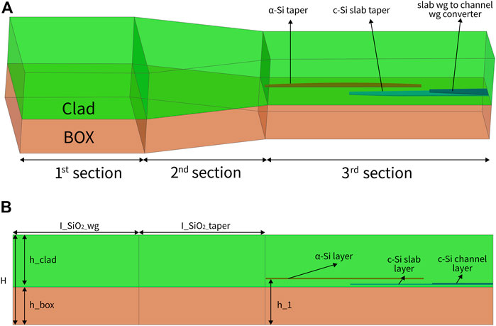
Figure 1A shows the structures of the double-layer cantilevered edge coupler. The whole device includes three sections. The first section is the SiO2 waveguide, which is designed for the better mode matching with the standard cleaved fibers. The second section is the SiO2 taper that compresses the mode in the horizontal direction. This middle section is use to compress the large mode spot into the small spot which matches with the α-Si nano taper. Both BOX and cladding layers are used to get the SiO2 waveguide. The third section consists the α-Si layer taper which is located in the center of the SiO2 waveguide, and the c-Si taper based on the top silicon layer of the SOI wafers. With the introduced α-Si layer, the thicker oxide buffer layer (h_1) is applied for the better mode matching and process variations as shown in Figure 1B. SiO2 waveguide facets are designed for the better mode matching with SMFs. To overcome the limitation of the finite BOX thickness, the α-Si layer is introduced on top of the c-Si waveguide SiO2 layer. The optical signal from the optical fiber is first coupled into the suspended SiO2 waveguide. Then, the optical signal propagates in the suspended SiO2 waveguide and is compressed by the SiO2 taper. Then, the optical signal is coupled into the α-Si nano taper in the center of the SiO2 waveguide, and finally into the c-Si nano taper.
A cross-section of 7 μm (width)*7.1 μm (height) is designed for the SiO2 waveguide end facet. As such, the α-Si nano taper is near the center of suspended SiO2 waveguide, allowing for optimal coupling efficiency between the suspended SiO2 waveguide ang the a-si nano taper. With the designed cross-section, the requirement on cladding index is also relieved. For optimum device performance, the mode conversions between the SiO2 waveguide and α-Si waveguide, the α-Si and c-Si waveguides are optimized separately. The detailed design parameters of the coupler are shown in Table 1. Figure 2 shows the top view of the double-layered edge coupler and denotations of the design parameters. Considering the coupling between the α-Si and c-Si layer, the α-Si layer thickness is designed to be 110 nm and the gap between two layers is 500 nm. The tip width of the α-Si nano taper is critical for the coupling loss.
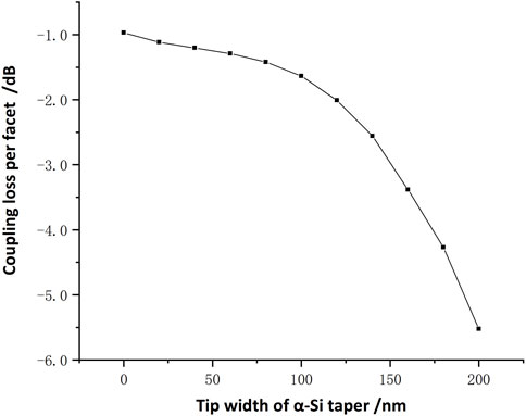
This edge coupler transmits as an input signal at 1,550 nm using the normalized fiber mode field. The material of matching liquid (n = 1.4) is used as the cladding for cantilevered SiO2 waveguide. The simulation results of TE mode are shown in Figure 3. X axis is the horizontal direction. Y axis is the vertical direction and Z axis is optical signal propagation direction. The optical field distribution results show that optical mode-size can be compressed into a small one in both horizontal and vertical directions through the 3D SiO2 taper. The right figure is the results of the monitored optical power in the converter. The conversion efficiency for TE mode is achieved as high as 80% with the optimized parameters. After that, the tip width of the α-Si nano taper at the center of the SiO2 waveguide is an important factor. We changed the tip width of the α-Si nanotaper. The simulated data is shown in Figure 4. When the width is 0 μm, the coupling loss can be optimized to 0.97 dB.
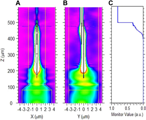
FIGURE 3. Simulated optical field distribution in the converter at 1,550 nm. (A): Top view; (B): Lateral view; (C): monitored optical power in the converter (blue line: the power in the c-Si overlapped tapers).
The double-layered edge coupler is fabricated on a 200 mm diameter wafer using CMOS compatible processes. The process flow chart is shown in Figure 5. The ridge and channel waveguides are first made by typical lithography/etch processes. After depositing 75 nm SiO2 by PECVD as the hard mask (HM), the waveguide and top c-Si taper structures were patterned by deep UV lithography technology, as shown in Figure 5A. The pattern size of the photo-resist (PR) is closed to the design value. Then, the PR pattern is trimmed with oxygen (O2) gas, after which the SiO2 hard mask is etched. The SiO2 hard mask is opened using carbon tetrachloride (CF4) and the c-Si is partially etched with chlorine (Cl2) and oxygen (O2), as shown in Figure 5B. The top c-Si nano taper is formed by the first partial SiO2 etch. The wafer was patterned and trimmed again, and the remaining c-Si was etched with Cl2 to complete the bottom c-Si nano taper, as shown in Figure 5C,D. Figure 6A shows the scanning electron microscope images (SEM) of the taper tip of the c-Si slab layer, and Figure 6B shows the SEM image of the transition from the c-Si slab layer to c-Si channel layer. Then, the SiO2 layer is deposited and the Chemical Mechanical Polishing (CMP) process is applied to smooth the surface and control the distance between the two Si layers, as shown in Figure 5E. After the 110 nm layer of α-Si was deposited in a gas-filled 540-degree furnace tube, the 75 nm of SiO2 was deposited by PECVD as the hard mask (HM), as shown in Figure 5F. The PR is applied and trimmed and patterned, then the SiO2 hard mask is etched to form the top α-Si nano taper, as shown in Figure 5G. The TEM image of the double-layer waveguides cross-section is shown in Figure 6C. After forming the top α-Si nano taper, a 3.5 μm PECVD SiO2 layer was deposited, and the 1 μm-thick SiO2 layer was then patterned and etched, as shown in Figure 5H. Later, the SiO2 waveguide and deep trench are pattern, as shown in Figure 5I. After patterning, the SiO2 layer is etched with octafluorocyclobutane (C4F8) and the Si layer is etched with sulfur fluoride (SF6) to form suspended SiO2 waveguide and Si deep trenches, as shown in Figure 5J. Figure 6 shows the SEM and TEM images of the double-layer edge coupler. The double-layer edge coupler is shown in Figure 6D.
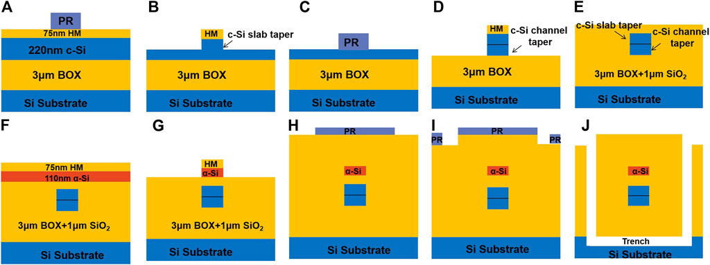
FIGURE 5. Process flow of edge-coupler.(A)Pattern mask 1,(B)Partially etch SiO2/c-Si,(C)Pattern mask 2,(D)Etch c-Si to BOX,(E)Deposited SiO2 layer,(F)Deposited α-Si layer and HM layer,(G)Partially etch SiO2/c-Si,(H)Pattern mask 3,(I)Pattern mask 4(J)etch SiO2/Si.
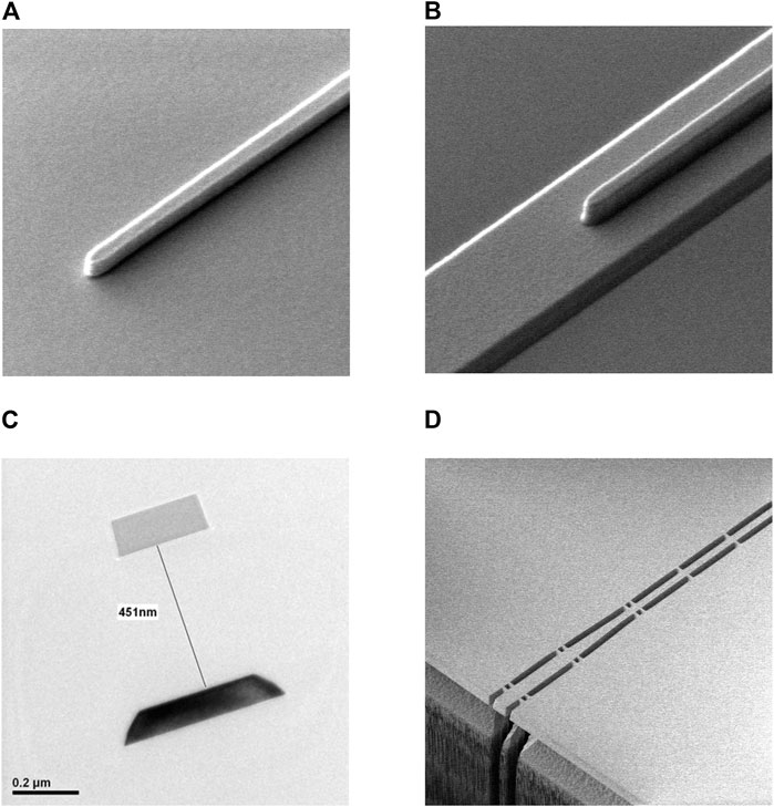
FIGURE 6. (A) SEM image of the taper tip of the c-Si slab layer, (B) SEM image of the transition from the c-Si slab layer to c-Si channel layer, (C)TEM image of the double-layer waveguides cross-section, (D)SEM image of the cantilevered structure (part).
Measurement and analysis
We characterized the fabricated devices with a simple transmission setup, which includes the high performance amplified spontaneous emission (ASE) light source with a broadband wavelength range, the high-sensitivity optical power meter, the optical polarization controller (PC), the high-precision optical spectrum analyzer (OSA) and a linear optical polarizer. Corning Panda Polarization Maintaining (PM) fibers are used with the mode field diameter of 10.5 μm at the wavelength of 1,550 nm. In order to ensure the TE mode input, the polarization direction of the linear polarizer is placed to be perpendicular to the chip surface. The output light through the polarizer is monitored by the near infrared (NIR) camera. By adjusting the polarization controller and rotating the input fiber, the output power is to be minimum. In order to extract the coupling performances, the Si waveguide is measured by the cut-back method. Each Si waveguide between input/output converters is composed of some straight waveguide (220 nm × 500 nm) and eight 180°-bend waveguide with a bending radius of 20 μm. The length difference between two adjacent Si waveguide is 6 mm.
The optical spectra of TE modes from the input PM cleaved optical fiber to the output.
PM cleaved optical fiber are measured first as a reference. Then, the same input/output optical fibers are used to measure the designed cut-back waveguide. Based on the above measured spectral (Figure 7A), we calculated the coupling losses and the propagation losses of the waveguides are extracted at different wavelengths, as shown in Figure 7B. In the bandwidth of 1,520–1,620 nm, the TE-mode propagation losses are about 1.5 dB/cm and the coupling losses are about 1.7 dB/facet. Alignment tolerance is critical to assemble with fiber. For a commercial converter,a large alignment tolerance greatly benefits the package of optical products. Therefore, we performed measurements of the alignment data of the cantilever converter. We change the vertical and horizontal position of the launch field separately to get the alignment tolerance of the device. Figure 8 shows the measured results about the alignment tolerances. Figure 8A is the horizontal(X) direction, and Figure 8B is the verticai(Y) direction. Using the above cleaved fiber and matching liquid, the tolerances in both X and Y axes are ±2.0 μm for 1-dB excess losses. This can much release request to alignment precision.
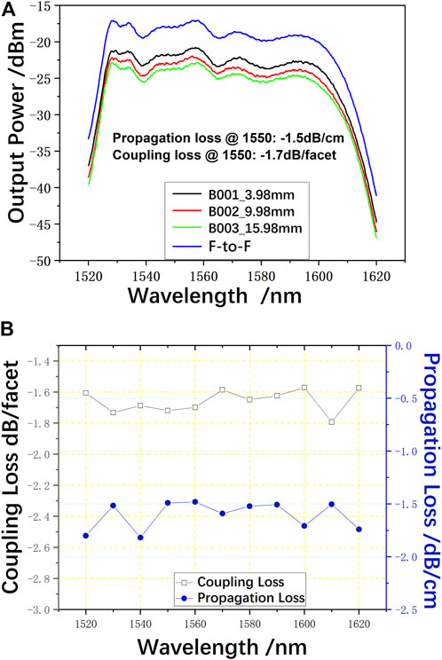
FIGURE 7. (A)Measured spectral for waveguides with different length and SMF-to-SMF reference, TE mode input; (B)extracted TE mode coupling loss with cleaved SMF and waveguide propagation loss. Index matching oil is not used in this test.
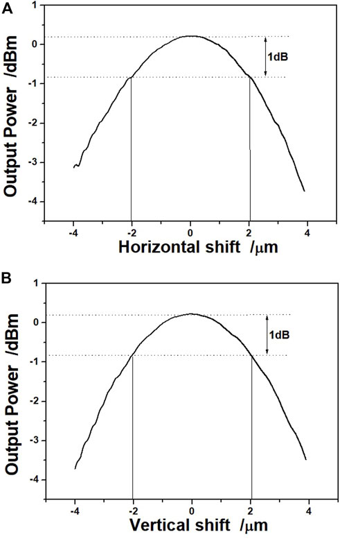
FIGURE 8. Alignment tolerance between mode size converter and cleaved optical fiber.(A) horizontal (X)directions,(B)vertical (Y) directions.
Comparison of different edge couplers
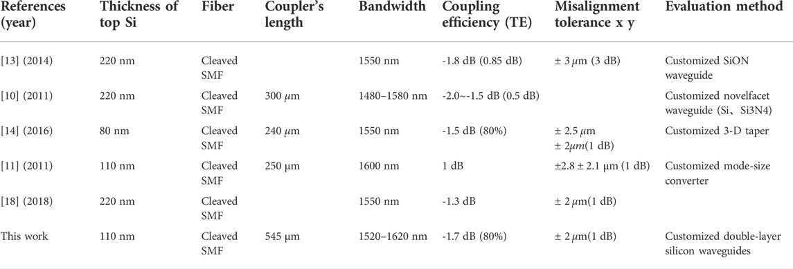
We compare the characteristics of the designed coupler with previous studies in Table 2. The thickness of top Si, coupling efficiency,misalignment tolerance,coupler’s length, fiber, bandwidth and evaluation method are compared in this table. When available both theoretical and experimental results are presented. To distinguish between the theoretical and experimental results in the table, we present the theoretical results in the parentheses. Our designed tapers have a double-layer silicon waveguide structure compared to other studies. The designed tapers have a coupling loss of less than 1 dB in a broad bandwidth of 1,550 nm, which is comparable with the previous studies. The design of this paper shows that the SiO2 waveguide and the c-Si waveguide have good coupling efficiency, which means that the top α-Si waveguide is located in the center of the SiO2 waveguide, which is more favorable for coupling.
Conclusion
We designed an ultra-low loss fiber-to-chip edge-coupler with the α-Si nano taper and the c-Si nano tapers. The coupling losses is 0.97 dB for TE modes by simulation, the measured coupling losses is as low as -1.7 dB per facet for TE mode at 1,550 nm without index matching liquid. The 1 dB bandwidth is more than 100 nm with 1 dB alignment tolerances of ±2.0 μm in both horizontal and vertical directions. Therefore, the design is favorable for the better coupling between the silica waveguide and the top silicon waveguide located in the center of the SiO2 waveguide.
Data availability statement
The original contributions presented in the study are included in the article/supplementary material, further inquiries can be directed to the corresponding authors.
Author contributions
All authors listed have made a substantial, direct, and intellectual contribution to the work and approved it for publication.
Funding
This work was supported by the National Key Research and Development Program of China (Grant No. 2018YFB2200500).
Conflict of interest
The authors declare that the research was conducted in the absence of any commercial or financial relationships that could be construed as a potential conflict of interest.
Publisher’s note
All claims expressed in this article are solely those of the authors and do not necessarily represent those of their affiliated organizations, or those of the publisher, the editors and the reviewers. Any product that may be evaluated in this article, or claim that may be made by its manufacturer, is not guaranteed or endorsed by the publisher.
References
1. Reed GT, Png CEJ. Silicon optical modulators. Mater Today (2005) 8(1):40–50. doi:10.1016/S1369-7021(04)00678-9
2. Lamont M, Okawachi Y, Gaeta ALJOL. Route to stabilized ultrabroadband microresonator-based frequency combs. Opt Lett (2013) 38(18):3478–81. doi:10.1364/ol.38.003478
3. Baehr-Jones T, Pinguet T, Lo Guo-Qiang P, Danziger S, Prather D, Hochberg M. Myths and rumours of silicon photonics. Nat Photon (2012) 6(4):206–8. doi:10.1038/nphoton.2012.66
4. Taillaert D, Bienstman P, Baets R. Compact efficient broadband grating coupler for silicon-on-insulator waveguides. Opt Lett (2004) 29(23):2749–51. doi:10.1364/OL.29.002749
5. Vivien L, Pascal D, Lardenois S, Marris-Morini D, Cassan E, Grillot F, et al. Light injection in soi microwaveguides using high-efficiency grating couplers. J Lightwave Technol (2006) 24(10):3810–5. doi:10.1109/JLT.2006.878060
6. Vermeulen D, Selvaraja S, Verheyen P, Lepage G, Bogaerts W, Absil P, et al. High-efficiency fiber-to-chip grating couplers realized using an advanced cmos-compatible silicon-on-insulator platform. Opt Express (2010) 18(17):18278–83. doi:10.1364/OE.18.018278
7. Shoji T, Tsuchizawa T, Watanabe T, Yamada K, Morita HJEL-I. Low loss mode size converter from 0.3 mum square Si wire waveguides to singlemode fibres. Elect Lett (2002) 38(25). doi:10.1049/el:20021185
8. Tsuchizawa T, Yamada K, Fukuda H, Watanabe T, Takahashi JI, Takahashi M, et al. Microphotonics devices based on silicon microfabrication technology. IEEE J Sel Top Quan Electron (2005) 11(1):232–40. doi:10.1109/jstqe.2004.841479
9. Fang Q, Liow TY, Song JF, Tan CW, Yu MB, Lo GQ, et al. Suspended optical fiber-to-waveguide mode size converter for silicon photonics. Opt Express (2010) 18(8):7763–9. doi:10.1364/oe.18.007763
10. Chen L, Doerr CR, Chen Y-K, Liow T-Y. Low-loss and broadband cantilever couplers between standard cleaved fibers and high-index-contrast Si N or Si waveguides. IEEE Photon Technol Lett (2011) 22(23):1744–6. doi:10.1109/LPT.2010.2085040
11. Fang Q, Song J, Luo X, Yu M, Lo G, Liu Y. Mode-size converter with high coupling efficiency and broad bandwidth. Opt Express (2011) 19(22):21588–94. doi:10.1364/OE.19.021588
12. Cordero-Davila A, Kantún-Montiel J, González-García J. Appling ronchi test to evaluate local and global surface errors without both approximations and integration. Imaging Appl Opt Tech Pap OSA Tech Dig (2012) JTu5A.13. doi:10.1364/AIO.2012.JTu5A.13
13. Jia L, Song J, Liow TY, Luo X, Tu X, Fang Q, et al. Mode size converter between high-index-contrast waveguide and cleaved single mode fiber using SiON as intermediate material. Opt Express (2014) 22(19):23652–60. doi:10.1364/oe.22.023652
14. Qing F, Junfeng S, Xianshu L, Tu X, Jia L, Yu M, et al. Low loss fiber-to-waveguide converter with a 3-D functional taper for silicon photonics. IEEE Photon Technol Lett (2016) 28(22):2533–6. doi:10.1109/LPT.2016.2602366
15. Jia LX, Liow TY, Li C, Luo XS, Tu XG, Huang Y, et al. High efficient suspended coupler based on ime's mpw platform with 193nm lithography. In: Optical Fiber Communications Conference and Exhibition (OFC); 2017 Mar 19-23; Los Angeles, CA. NEW YORK: IEEE (2017).
16. Ou X, Yang Y, Tang B, Li D, Li ZJ, Zhang P, et al. Low-loss silicon nitride strip-slot mode converter based on mmi. Opt Express (2021) 29(12):19049–57. doi:10.1364/oe.427802
17. Feng S, Gao Y. Analysis of coupling between nanotaper sige-soi waveguide and fiber. J Semicond (2014) 35(7):074010. doi:10.1088/1674-4926/35/7/074010
18. Jia L, Li C, Liow T-Y, Lo G-Q. Efficient suspended coupler with loss less than -1.4 dB between Si-photonic waveguide and cleaved single mode fiber. J Lightwave Technol (2018) 36(2):239–44. doi:10.1109/JLT.2017.2779863
Keywords: edge-coupler, c-Si nano tapers, α-Si nano taper, SOI platform, fiber-to-chip
Citation: Ma X, Hu H, Liu S, Dong R, Fang Q and Chen H (2022) The edge-coupler of fiber-to-chip with ultra-low coupling loss based on double-layer silicon waveguides. Front. Phys. 10:1018624. doi: 10.3389/fphy.2022.1018624
Received: 13 August 2022; Accepted: 13 September 2022;
Published: 03 October 2022.
Edited by:
Imran Avci, VU Amsterdam, NetherlandsReviewed by:
Venkatesha M, Sai Vidya Institute of Technology, IndiaSeyed Hadi Badri, Islamic Aazd university, Iran
Copyright © 2022 Ma, Hu, Liu, Dong, Fang and Chen. This is an open-access article distributed under the terms of the Creative Commons Attribution License (CC BY). The use, distribution or reproduction in other forums is permitted, provided the original author(s) and the copyright owner(s) are credited and that the original publication in this journal is cited, in accordance with accepted academic practice. No use, distribution or reproduction is permitted which does not comply with these terms.
*Correspondence: Qing Fang, c2VtaW9lbGFiQGttdXN0LmVkdS5jbg==; Hua Chen, Y2hlcnJ5Y2hlbjQwNjAwQDE2My5jb20=
 Xiaoyue Ma1
 Qing Fang