- 1College of Science, Kunming University of Science and Technology, Kunming, China
- 2College of Electronic Science and Engineering, Jilin University, Jilin, China
A low-crosstalk compact arrayed waveguide grating integrated with a tunable micro-ring resonator is demonstrated on silicon-on-insulator platform, The side-lobe of the silicon nanowire AWG, introduced by fabrication errors, can be effectively suppressed by the Ring Filter, The crosstalk level of the side-lobe can be reduced from -16.3 dB to -26.8dB, in addition, the crosstalk of integrate AWG have improved over the entire 3 dB bandwidth, with a maximum crosstalk improvement of 8.9 dB at the left and right wavelengths of the 3 dB bandwidth, and the excess loss from the ring resonator can be ignorable in principle.
1 Introduction
With the further improvement of communication capacity requirements, information multiplexing technologies such as Optical Time Division Multiplexing (OTDM), Optical Code Division Multiplexing (OCDM) and Wavelength Division Multiplexing (WDM) have been proposed one after another. As one of the most commonly used technologies in optical communication networks, WDM can maximize the use of bandwidth in optical fibers and effectively expand communication capacity. The silicon-based wavelength division multiplexer has received great attention due to its mature CMOS compatible process and platform. At present, the silicon-based wavelength division multiplexer (WDM) mainly has four structures, etched diffraction grating (Etched Diffraction Grating, EDG) [1, 2], Micro-Ring Resonator (MRR) [3–6], Mach Zander Interferometer (MZI) [7–10] and Arrayed Waveguide Grating (AWG) [11]. Compared to other technologies for multi-port optical filters, AWGs are compact, robust and suitable for large volume production.
In most AWG applications, the device’s insertion loss, channel crosstalk performance is critical. In the on-chip optical system, channel crosstalk below −20 dB is required. However, in practical applications, the channel crosstalk of silicon-based AWG is usually higher. Phase errors in waveguides caused by high refractive index cores is the main cause of AWG crosstalk, It has been demonstrated that compensating for this phase error can improve the filter performance and significantly lower the crosstalk level [12, 13], In order to remove the influence of side-lobe, a structure of cascaded AWGs is reported in [14], has achieved −34.2 dB crosstalk, and the insertion loss is −3.2dB, but the additional cascaded AWGs increase the device’s size. Subsequently, a low crosstalk Arrayed Waveguide Grating with Cascaded Waveguide Grating Filter was reported in [15], achieved 15 dB crosstalk improvement in simulation through cascade Waveguide Grating Filter, it is much more compact compared with the conventional AWG cascaded with AWGs design in [14], However, the Waveguide Grating Filter also has manufacturing errors and cannot perform wavelength tuning, so the actual performance may be degraded. In 2019, Zeng et al. proposed and demonstrated an integrated spectrometer with high resolution and wide bandwidth based on the cascaded AWG and tunable microring resonator array [16, 17]. However, the microring from each channel need to be tuning, which is very time-consuming.
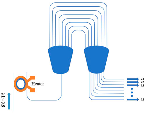
In this letter, a novel WDM structure by integrating an AWG and a heat-turning MRR is demonstrated on silicon-on-insulator (SOI) wafer. In this design, the drop port of MRR is connected with the input waveguide of the AWG, the FSR of MRR is strictly consistent with the channel wavelength spacing of the AWG, and the resonance peak of MRR can be thermally tuned to overlaps with the peak wavelength of the AWG respectively. Through this design, the MRR worked as a filter to shape the AWG side-lobe region, and the crosstalk of the device can be significantly reduced with little insertion loss change. As a comparison, conventional AWG and this design is fabricated on the same chip, The experimental results shows that the side-lobe crosstalk level of the conventional AWG is −16.3 dB, 3 dB bandwidth is 1.72 nm, the crosstalk magnitude at the bandwidth maximum of the 3 dB bandwidth is −10.3 dB, insertion loss is −3 dB. The crosstalk of MRR integrate AWG at the bandwidth maximum of the 3 dB bandwidth is reduced by 8.9 dB, with 0.8 dB insertion loss increase, and the crosstalk at side-lobe reduced from −16.3 to −26.8 dB. After integrated MRR, the side-lobe of low crosstalk AWG has effectively eliminated, within the overall 3 dB bandwidth, the crosstalk levels of the devices are improved, with a maximum crosstalk magnitude difference of 8.9 dB.
2 Design and fabrication
The schematic low crosstalk AWG is shown in Figure 1, it consists of two main components: a heater-tunable MRR and an AWG. The drop port of MRR is connected with the input waveguide of the AWG. In order to make sure the resonance peak of MRR overlaps with the peak wavelength of the AWG strictly, the design of the FSR of the microring and the channel wavelength spacing of the AWG are essential. For AWG, according to the design requirements, it is determined that the center wavelength
Due to fabrication variation, the resonance wavelength cannot be precisely controlled by simply changing the dimensions of the MRR. Based on the high thermo-optic coefficient of silicon, the refractive index of silicon material changes with temperature, the resonance wavelength shifts with temperature, so the heater-tunable MRR adopted here can actively control the resonance wavelength well. In addition to the resonance wavelength shift, fabrication variation will also cause the FSR of the microring to deviate from the design value, in order to achieve strict matching between the FSR of the microring and the channel wavelength spacing of the AWG, in addition to integrating eight different MRR in the input waveguide of the AWG, we designed independent microrings with different radius and conventional AWG on the chip, by testing independent devices, we can get the smallest matching error MRR under the condition of process errors.
To simulate the transmission spectrum of low crosstalk AWG integrate with MRR filter, Kirchhoff diffraction theory was used to calculate the transmission spectra of integrate AWG in this work [18], Figure 2 focus on display the transmission spectra of AWG, MRR filter, and the integrated AWG at 1550 nm central wavelength together, from the simulation of Figure 2, the FSR of MRR is 3.2 nm, and the maximum extinction ratio of the micro-ring is −20 dB, the side lobe crosstalk level of conventional AWG is −14.4 dB at 1,551.38 nm, by integrate the microring, the crosstalk level at 1,551.38 nm of side lobe is reduced to −33.1 dB in low crosstalk AWG. The simulation result indicating that an MRR introduced at the input of the experimental AWG can effectively filter out the side-lobe and shape the main peak waveform, the crosstalk level of side lobe at 1,551.38 nm is reduced by 18.7 dB.
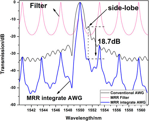
FIGURE 2. Transmission spectra of AWG, MRR filter, and the integrated AWG at 1550 nm central wavelength.
The key of the design is to ensure that the FSR of the microring is strictly consistent with the AWG channel spacing, in the simulation results, the calculated transmission spectrum of the MRR and AWG is all shown in Figure 3A, The resonance peak of the micro-ring overlaps with the peak wavelength of the AWG respectively. The spectrum diagram of MRR integrate AWG after overlapping is shown in Figure 3B, according to the simulation in Figure 3B, The microring is worked as a filter to shape the AWG side lobes, The suppression effect on the side-lobe is average 19 dB. The simulated performance of conventional AWG and low crosstalk AWG is shown in Table 1. Compared with the conventional AWG, the waveform of low crosstalk AWG integrate with MRR is steeper. At the same time, the side lobe crosstalk level caused by the process error is reduced from −14 dB to −33 dB, achieving a 19 dB improvement. Due to the filtering effect of the micro-ring filter, the 3 dB bandwidth of the AWG is reduced by 0.72 nm, but within the 3 dB bandwidth, the overall crosstalk level of the cascaded MRR device is better than that of the conventional AWG, where the minimum crosstalk is at the maximum value of the 3 dB bandwidth and the crosstalk is −33.4 dB. MRR integrated with AWG achieves an 8.4 dB boost compared to the −25 dB crosstalk of a conventional AWG at 3 dB maximum bandwidth and improves crosstalk performance over the entire 3 dB bandwidth.
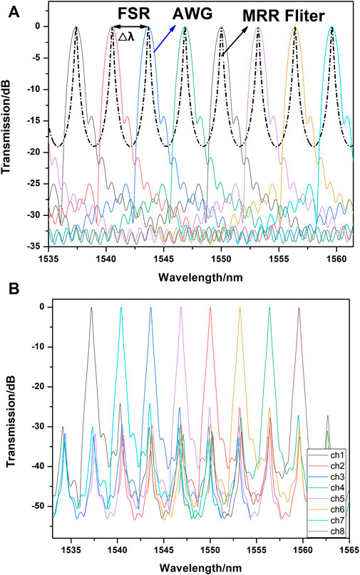
FIGURE 3. (A) Transmission spectrum of 8 output channels of conventional AWG and MRR filter. (B) Transmission spectrum of 8 output channels of low crosstalk AWG integrated with MRR filter.
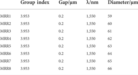
The main structure of the device we designed in this paper is one micro-ring integrate one AWG, the footprint of the integrated device is mainly determined by the AWG, the core size of AWG is 800 μm × 500 μm, and the footprint of the microring is 150 μm × 150 μm, including the size of heater and electrode. Compared to conventional AWG, the obtained device is similar in size, in the layout design, to reduce the matching error of micro-ring and AWG caused by manufacturing error, eight different radius microrings are integrated with the AWG in Figure 4, and select the microring with the smallest error to test the crosstalk after connecting the AWG. Besides, in order to ensure that the MRR working spectral band matches the transmission spectrum of the AWG in testing, we designed a thermally tuned MRR (TiN heater), When the MRR is thermally tuned, the resonance wavelength will be shifted to λr with respect to the initial value λ0, the shift △λ is defined as λr−λ0 and △λ is smaller than FSR of the MRR. Figure 4 shows an optical micrograph of the fabricated low-crosstalk AWG consisting of a tunable MRR filter and an AWG. Microrings with different diameters, ranging from 59 μm to 66 μm, are integrated into the 8 input waveguides of the AWG, which avoids the problem of mismatch between the MRR operating spectral band and the transmission spectrum of the AWG due to process errors. The chip is fabricated on silicon-on-insulator (SOI) platform with a 220 nm silicon layer and a 2 μm silicon dioxide insulating layer, For MRR, the width of all straight waveguides is 500 nm, the ridge height is 220 nm, the width of the ridge waveguides in the ring is also 500 nm, the gap between the ring and the bus waveguide is 200 nm, the ring diameters of adjacent MRRs differ by 1 μm, the smallest diameter of the eight MRR is 59 μm and the largest diameter is 66 μm. The parameters of the eight MRR devices cascaded in the AWG input waveguide are shown in Table2. For the AWG, it consists of eight input and eight output channels, the free propagation regions (FPR) connect the input and output regions through 23 waveguide arrays The length difference of the waveguide array is 10 um, the output channel waveguide spacing is 49.5 μm, the output waveguide is a strip waveguide with a width of 0.5 μm, and the ridge waveguide is designed for the waveguide array with a width of 0.8 μm to reduce the optical fiber caused by manufacturing variation [19], loss and phase error. The design parameters of AWG are shown in Table 3, in Table 3, Nout is the number of output waveguides, λ0 is the center wavelength, R is the focal length, △λ is the channel spacing, m is the diffraction order, N is the number of arrayed waveguides, do is the output waveguide spacing, and da is the arrayed waveguide spacing. Neff is the waveguide effective refractive index, ng is the group refractive index, and ns is the plate refractive index.
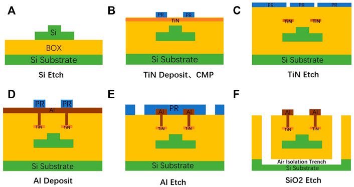
The sectional structure of MRR is shown in Figure 5, fabricated on a SOI wafer (220 nm top Si layer) by the standard CMOS fabrication processes. The 248 nm deep ultraviolet optical lithography is used. As shown in Figure 5A, the waveguide is firstly formed by lithography and partially etching processes, the rib of the waveguide has a width of 500 nm and etch the slab of 90 nm [20]. Subsequently, an upper SiO2 cladding layer of 1.5 μm is deposited through PECVD (plasma-enhanced chemical vapor deposition) process, and the Chemical Mechanical Polishing (CMP) process is applied to smooth the surface, In Figure 5B, a 120 nm thick TiN metal was deposited and etched above the Si waveguide, the etched TiN electrode is shown in Figure 5C, Then, continue to deposit 2 μm thick silicon dioxide material on the chip by LPCVD, and etch the silicon dioxide layer on the TiN metal to form contact holes. Afterwards, 2 μm-thick Al layer was deposited in Figure 5D, and the 2 μm-thick Al layer was then patterned and etched to form the electrode as shown in Figure 5E. Finally, the trenches were formed by sequentially dry etching the adjacent SiO2 layer, and sulfur fluoride (SiF6) was used as etching ion source to etch Si substrate in Figure 5F, the trenches can well reduce the thermal crosstalk and enhance the thermal modulation efficiency.
3 Characterization and analysis
Transmission-type test method using end-face coupling, using a tunable laser source ASE (EXFO OSICS-8) 6.3 mw output power with 1,550 nm center wavelength module, the measurement setup includes a polarization controller, rotatable fiber holder, an optical polarizer, and a 6-axis automatic alignment system. Measurements were performed after selecting transverse electrical (TE) polarization. The chip is placed on Newport’s 6-axis aligned coupled system-on-chip stage. Make sure that the chip stage is level and the height is appropriate before placing the chip, the input/output fiber is fixed on the input/output robotic arm, in the X/Y/Z direction. The stroke of the upper manipulator is 25 × 25 × 25μm, and the step accuracy is 1 nm. By adjusting the input/output manipulator, fiber orientation position and angle can be determined, the alignment coupling system also includes a near-infrared CCD, located on the right side of the output end, the output light spot can be observed to determine whether the input optical signal is coupled into the chip. Photonic Dispersion and Loss Analyzers are used to characterize the optical performance of tunable filters.
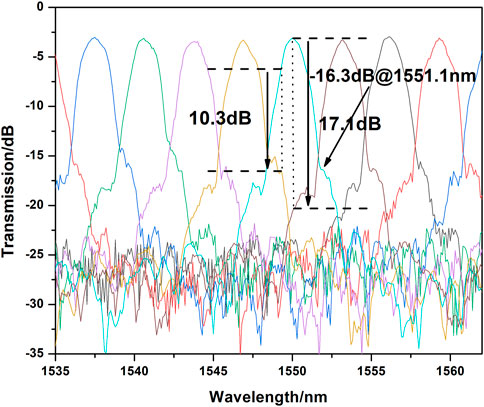
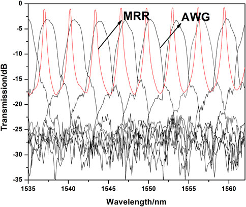
Figure 6 shows the transmission spectra of the 8 output channels of the conventional AWG, the average channel spacing of AWG is 3.191 nm, the average insertion loss of the conventional AWG is about −3dB, the adjacent channel crosstalk at the center wavelength of 1550 nm is −17.1 dB, The sidelobe level of channel 4 is −16.3 dB, the 3 dB bandwidth is 1.72 nm, Within the 3 dB bandwidth, with the increase of the bandwidth, the crosstalk increases from −17.1 dB to −10.3 dB, and the maximum crosstalk is at the left and right limit of the 3 dB bandwidth.
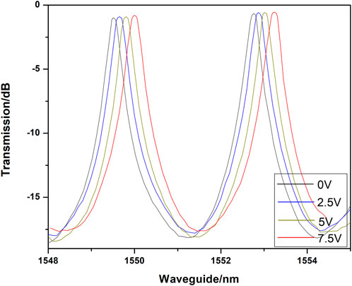
Due to manufacturing differences, the FSR of the MRR cannot be precisely controlled by simply design the diameter of the MRR. In order to ensure that the FSR of the microring is strictly consistent with the channel wavelength spacing of the AWG Accurately, we tested eight MRRs fabricated with a diameter difference of 1 μm and conventional AWG, respectively. Among them, the FSR of MRR4 is most consistent with the channel wavelength spacing of AWG. Figure 7 is the transmission spectra of conventional AWG and MRR4, the resonance wavelength measure result of MRR4 and the center wavelengths of the experimental conventional AWG are shown in Table 4. The deviation between the FSR of the microring and the wavelength spacing of the AWG channel is below 0.06 nm. Compared with the simulation results, the center wavelength of each channel in the experimental AWG has a red shift of 0.25 nm and the center wavelength of MRR has a blue shift of 0.3 nm. To matches the transmission spectrum of the AWG strictly, the heater-tunable MRR is adopted to actively control the resonance wavelength. Figure 8 shows the resonance wavelength change of MRR4 with the increasing voltage, the resonance wavelength shift of the MRR is 0.55 nm at an applied voltage of 7.7 V, this shift of resonance wavelength can eliminate the effect of wavelength blue shift by manufacturing variation, and realize strongly overlap with the resonance wavelength of the MRR and the AWG channels.
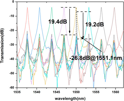
Figure 9 is the transmission spectra from 8 output channels of the AWG integrated MRR filters, through by analyze the output channel 5, the insertion loss at the center wavelength of 1550 nm is −3.95 dB, the adjacent channel crosstalk is - 19.4 dB, the crosstalk at the left and right limit of the 3 dB bandwidth is −19.2 dB, which is similar to the center crosstalk, the 3 dB bandwidth is 0.31 nm.
In the test of the conventional AWG in Figure 6, side-lobe due to manufacturing errors is −16.3 dB, the crosstalk at the left and right limit of the 3 dB bandwidth is as high as −10.3 dB. But after cascading MRR4, through the filtering effect of MRR, the crosstalk level at the side-lobe is reduced to −19.2 dB. In addition, the crosstalk of the AWG cascaded MRR filter at the left and right limit of the 3 dB bandwidth is average −19.2 dB, which is 8.9 dB lower than that of the conventional AWG, this is mainly because the primary filtering effect of the MRR shapes the waveform of the AWG spectrum, so that the energy is concentrated near the main peak, which not only eliminates the side-lobe that appear due to process errors, also greatly improves crosstalk levels across the entire 3 dB bandwidth. Table 5 is the comparison of the performance of conventional AWG and low crosstalk AWG. while the insertion loss of the AWG cascaded MRR filter is slightly higher (about −3.8 dB), compared to the average insertion loss of the conventional AWG (−3 dB). The reason for the 0.8 dB increase in insertion loss is mainly the introduction of MRR devices, and the excess loss from the ring resonator can be ignorable in principle.
4 Conclusion
We demonstrated a compact AWG with low crosstalk consist of a tunable MRR on SOI platform, The microring is worked as a filter to shape the AWG side-lobe, and the fabrication errors induced crosstalk in silicon nanowire AWG is efficiently suppressed. Through contrast with conventional AWG on the same chip, the crosstalk of side-lobe is improvement as high as 10.5 dB, the crosstalk at the maximum and minimum wavelength of the 3 dB bandwidth is reduced by 9 dB, it also effectively improves the crosstalk level within the entire 3 dB bandwidth. and the insertion loss is only increased by 0.8 dB. Therefore, the AWG designed in this paper with ring filter method can effectively reduce the crosstalk of the device.
Data availability statement
The original contributions presented in the study are included in the article/Supplementary Material, further inquiries can be directed to the corresponding authors.
Author contributions
All authors contributed to the article and approved the submitted version. QF and HC are co-corresponding authors. SL and HH contributed equally to this work and share first authorship.
Funding
This work is supported by the National Key Research and Development Program of China (Grant No.2018YFB2200500), Yunnan Provincial Foundation Program (202201AT070202).
Conflict of interest
The authors declare that the research was conducted in the absence of any commercial or financial relationships that could be construed as a potential conflict of interest.
Publisher’s note
All claims expressed in this article are solely those of the authors and do not necessarily represent those of their affiliated organizations, or those of the publisher, the editors and the reviewers. Any product that may be evaluated in this article, or claim that may be made by its manufacturer, is not guaranteed or endorsed by the publisher.
References
1. Sheng ZY, He SL, He JJ, Fang Y. Design and simulation for etched diffraction grating for dwdm in optical communication. Guangzi Xuebao/Acta Photonica Sinica (2001) 30(5):567.
2. Song J, Zhu N. Analysis method of the effect of fabrication errors on a planar waveguide demultiplexer. Opt Quan Electron (2006) 38(15):1203–16. doi:10.1007/s11082-006-9019-7
3. Bhowmik BB, Gupta S, Gangopadhyay R. Simultaneous demodulation and dispersion compensation of wdm dpsk channels using optical ring resonator. Opt Commun (2012) 285(16):3483–6. doi:10.1016/j.optcom.2012.04.005
4. Almasian MR, Abedi K. A proposal for optical wdm using embedded photonic crystal ring resonator with distributed coupling. Physica E: Low-Dimensional Syst Nanostructures (2016) 79:173–9. doi:10.1016/j.physe.2016.01.001
5.Xu DX, Densmore A, Ma R, Schmid JH, Vachon M, Lapointe Jet al. editors. Wdm addressed soi ring resonator biosensor array, 2009. San Francisco, CA, United states: IEEE Computer Society (2009).IEEE International Conference on Group IV PhotonicsSeptember 9, 2009 - September 11, 2009.
6.Lee H-S, and Lee E-H, editors. Improved quality factor of a silicon micro-ring resonator for wdm filter application. Sorrento, Italy: IEEE Computer Society (2008).International Conference on Group IV Photonics, GFPSeptember 17, 2008 - September 19, 2008.
7.Wong HY, Tan WK, Bryce AC, Marsh JH, Arnold JM, and Sorel M, editors. Integrated asymmetric mach-zehnder interferometer wdm (De)Multiplexer using quantum well intermixing. 2005 international Conference on indium Phosphide and related materials, 2005. Glasgow, Scotland, United kingdom: Institute of Electrical and Electronics Engineers Inc (2005).May 8, 2005 - May 12.
8.Krishnamoorthy AV, Zheng X, Li G, Dong P, Feng D, Pinguet Tet al. editors. Dense wdm silicon photonic interconnects for compact high-end computing systems, 2011. IEEE Winter TopicalsIEEE Computer Society (20112011).
9. Feng S, Gao Y. Optimization of the micro-nano pin electro-optic modulator. Guangdianzi Jiguang/Journal of Optoelectronics Laser (2014) 25(5):870–5.
10.Feng S, Wang W, Brian SJX, Guo X, Zhou J, Qiao Zet al. editors, 2019. China: Institute of Electrical and Electronics Engineers Inc (2019).The design of 1 2 mmi at the mir wavelength of 2mIEEE International Conference on Electron Devices and Solid-State Circuits, EDSSC 2019June 12, 2019 - June 14, 2019xi'an.
11. Yang Y, Hu X, Song J, Fang Q, Yu M, Tu X, et al. Thermo-optically tunable silicon awg with above 600 Ghz channel tunability. IEEE Photon Technol Lett (2015) 27(22):2351–4. doi:10.1109/LPT.2015.2464073
12. Hibino Y. Recent advances in high-density and large-scale Awg multi/demultiplexers with higher index-contrast silica-based plcs. IEEE J Sel Top Quan Electron (2002) 8(6):1090–101. doi:10.1109/JSTQE.2002.805965
13. Takada K, Tanaka T, Abe M, Yanagisawa T, Ishii M, Okamoto K. Beam-adjustment-free crosstalk reduction in 10 Ghz-spaced arrayed-waveguide grating via photosensitivity under uv laser irradiation through metal mask. Electron Lett (2000) 36(1):60–1. doi:10.1049/el:20000021
14. Kamei S, Kaneko A, Ishii M, Shibata T, Inoue Y, Hibino Y. Crosstalk reduction in arrayed-waveguide grating multiplexer/demultiplexer using cascade connection. J Lightwave Technol (2005) 23(5):1929–38. doi:10.1109/jlt.2005.846909
15. Deng Y, Liu Y, Gao D. Low crosstalk arrayed waveguide grating with cascaded waveguide grating filter. J Phys : Conf Ser (2011) 012055. doi:10.1088/1742-6596/276/1/012055
16.Zhu HH, Zheng SN, Zou J, Cai H, Li ZY, and Liu AQ, editors. A high-resolution integrated spectrometer based on cascaded a ring resonator and an awg. 2020 Conference on Lasers and electro-optics. San Jose, CA, United states: Institute of Electrical and Electronics Engineers Inc (2020).CLEOMay 10, 2020 - May 15, 2020.
17. Zheng S, Cai H, Song J, Zou J, Liu PY, Lin Z, et al. A single-chip integrated spectrometer via tunable microring resonator array. IEEE Photon J (2019) 11(5):1–9. doi:10.1109/jphot.2019.2939580
18. Dai D, Liu L, He S. Three-dimensional hybrid modeling based on a beam propagation method and a diffraction formula for an awg demultiplexer. Opt Commun (2007) 270(2):195–202. doi:10.1016/j.optcom.2006.08.051
19. Yang W. An analytic approach to random phase error and its impact on the performance and design of arrayed-waveguide gratings. IEEE J Quan Electron (2007) 43(7):568–71. doi:10.1109/jqe.2007.897930
Keywords: arrayed-waveguide grating (AWG), crosstalk, micro-ring resonator, silicon photonics, SOI platform
Citation: Liu S, Hu H, Ma X, Dong R, Fang Q and Chen H (2022) Low-crosstalk silicon-photonics arrayed waveguide gratings integrated with micro-ring filter. Front. Phys. 10:1018589. doi: 10.3389/fphy.2022.1018589
Received: 13 August 2022; Accepted: 23 September 2022;
Published: 07 October 2022.
Edited by:
Chuanbo Li, Minzu University of China, ChinaCopyright © 2022 Liu, Hu, Ma, Dong, Fang and Chen. This is an open-access article distributed under the terms of the Creative Commons Attribution License (CC BY). The use, distribution or reproduction in other forums is permitted, provided the original author(s) and the copyright owner(s) are credited and that the original publication in this journal is cited, in accordance with accepted academic practice. No use, distribution or reproduction is permitted which does not comply with these terms.
*Correspondence: Qing Fang, c2VtaW9lbGFiQGttdXN0LmVkdS5jbg==; Hua Chen, Y2hlcnJ5Y2hlbjQwNjAwQDE2My5jb20=
†These authors have contributed equally to this work and share first authorship
 Shiping Liu1†
 Qing Fang