 Keshia Mekemeza-Ona
 Benoît Charbonnier
94% of researchers rate our articles as excellent or good
Learn more about the work of our research integrity team to safeguard the quality of each article we publish.
Find out more
ORIGINAL RESEARCH article
Front. Phys., 16 November 2022
Sec. Optics and Photonics
Volume 10 - 2022 | https://doi.org/10.3389/fphy.2022.1017714
This article is part of the Research TopicEditor's Challenge in Optics and Photonics: Advancing Electronics with PhotonicsView all 6 articles
This paper studies theoretically the use of a Q-switch laser with side light injection as a spiking all-optical neuron for photonic spiking neural networks (PSNN). Ordinary differential equations for the multi-section laser are presented, including terms for the side light injection for gain quenching and saturable absorption. The behaviour of the laser mimics that of a spiking neuron with ultrafast pico-second scale response and low power control signals.
Neuromorphic computing aims to emulate the brain’s ability to process large amounts of information efficiently. Since the 1980s [1], this field has continued to evolve as we have improved our understanding of brain physiology, as well as hardware innovation. As a result, functional neuromorphic chips were first implemented using electronic platforms [2]. However, neuromorphic electronics is facing important limitations related to bandwidth and integration density [3, 4]. More recently, silicon photonics technology has emerged as a potential platform for scaling up neuromorphic devices [3], and might be an answer to meeting this technological challenge regarding complexity, interconnection and also power consumption especially when IIIV based devices can be integrated along other passive and active components [5, 6].
Neuromorphic hardware is based on models of artificial neural networks (ANNs). Spiking neural networks (SNNs) are the most bio-realistic form of them, as they operate using discrete spatio-temporal spikes, much like biological neurons [7]. Since they have a temporal aspect, SNNs are capable of processing spatio-temporal information, leading to more complex applications such as feature recognition, image classification, audio recognition, etc [3, 7]. In addition, unlike conventional ANNs, they only operate when spikes occur, which makes their hardware much more energy efficient.
Models of spike neurons have been proposed to simulate most biological features of neurons [8]. Among them, the Leaky Integrate-and-Fire (LIF) offers the best compromise between biological plausibility and practicality [2, 9], which explains its widespread use in the literature. In neuromorphic photonics, the excitability of spiking neurons has already been demonstrated by using excitable semiconductor lasers, also known as spiking lasers [10–12]. Saturable absorber is typically used in such lasers, resulting in non-linearities that give the lasers either bistability or spiking behavior [13]. The latter is usually the result of a Q-switch mechanism. Spiking lasers can be divided into two categories based on how optical spikes are generated: optical-electrical-optical (O/E/O) and all-optical [3]. In most cases, O/E/O spiking lasers rely on electronic circuits to control their excitable dynamics. In contrast, all-opticall lasers are directly excited by optical perturbations. Various all-optical laser designs have been proposed in references [14–16].
In this paper we first describe the architecture of an all-optical side light-injected Q-switch laser. Then, we solve his Ordinary Differential Equations (ODE) to determine its behavior as a spiking neuron: integration of incoming synaptic signals, exitability, inhibitability and spike response, refractory period. Once this is set, we demonstrate the cascadability and the optical memory ability of our laser in a two-neurons mutually coupled circuit.
Q-switched lasers have been proposed in [10] to serve as spiking neurons owing to their capacity to integrate in a leaky way the incoming energy over time and fire an output pulse when that energy increases above an internal threshold. Electrical command signals have been proposed and demonstrated [17–20] using balanced photodetectors to modulate the bias current of the gain section. Optical command signals have also been proposed in [21] but require a complex implementation. Indeed, as these signals are injected along the main laser cavity, they interact mainly with the gain section of the laser and hence provide only gain quenching (by increasing stimulated emission and hence reducing the exited carrier concentration). As a result, incoming pulses can only be used as inhibitors to the laser-neuron. Excitability requires the optical signals to be reversed, leading to additional hardware to be employed [21].
In [22], a side light-injected bistable laser was developed and tested for applications in all-optical digital signal processing. The laser was composed of five sub-sections along the main optical cavity. Three sections were devoted to pure gain with a direct bias (current injection) while one section was devoted to gain quenching and another one to saturable absorption. The two later sections had perpendicular waveguides connected to them, allowing light to be injected directly into those sections without creating a large crosstalk with the main waveguide. Overall, the laser was designed to have a bistable operation. In its general operation, the gain section is biased slightly under the laser threshold. By injecting light in the side waveguide connected to the gain quenching section (resp. the saturable absorption section), additional radiative recombinations by stimulated emission (resp. carrier excitation by photon absorption) occurs hence locally reducing (resp. increasing) the population inversion and as a result creating a sudden drop in the cavity gain (resp. drop in the cavity loss). Subsequently, the laser would switch-off (resp. switch-on). A similar behavior can be applied to a Q-switch laser to obtain all optical excitability or inhibition as in spiking neurons.
In the following section, we describe sush laser layout and parameters and write the ODEs describing its behaviour.
The Q-switch laser is based on five sections as in [22]. A schematic view of its structure integrated on a silicon photonics platform is represented in Figure 1. Two side light injected sections are sandwiched between three generic gain sections which provide the main photon generation and amplification functions for the longitudinal laser cavity. The three gain sections are directly biased together by a single electrode (respective currents denoted iG,1, iG,2, and iG,3) while the two other sections have their own electrical electrodes. A direct bias is also applied to the gain quenching section (iQ) and a zero or small reverse bias to the SA section (iSA). Using the formalism from [17] (Figure 2), we write the ODEs that describe the time evolution of the carriers and photons in the different sections of the laser. Note that there will be three different photon populations: the one in the longitudinal waveguide Nph plus the ones in the lateral waveguides NQ and NSA. According to [23], the wavelengths of these photon populations have to be within the III-V material absorption spectrum but may not be exactly the same. However, for the sake of simplicity we will assume similar wavelengths and hence that the same gain/absorption coefficients can be used in the equations. First, for the carrier concentration in the main gain sections (m = 1, 2 or 3):
where nG,m is the carrier concentration in the considered section, η the current injection efficiency, VG,m the section’s volume, τG the carrier lifetime, gG the differential gain, nG,0 the carrier density at transparency, Nph the photon population in the overall longitudinal cavity and Vtot the total volume of the main cavity. Now, for the gain quenching section, we write:
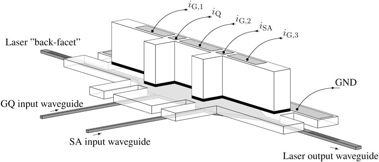
FIGURE 1. 3D-Schematic view of the neuron laser: the IIIV material is processed on top of an silicon photonics wafer to allow coupling between the underlying silicon waveguides and the gain material. Biasing currents are injected into the top electrodes (InP+) through the quantum wells (represented as a black layer) to the ground electrode (InP−). Two waveguides perpendicular to the main laser cavity are used to feed optical power directly into the GQ and SA parts of the laser. The detailed structure of the laser can be inferred from [5, 6].
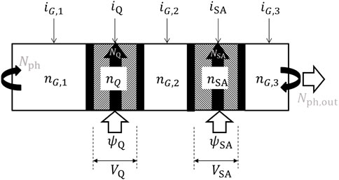
FIGURE 2. Schematic view of the neuron laser detailing the different variables of the model.
For the saturable absorption region:
the parameters are self-explanatory. Note that Vtot = VG,1 + VQ + VG,2 + VSA + VG,3. Finally, for the photon populations, we write:
where β and Br are respectively the spontaneous emission coupling factor and the bimolecular recombination term. In Eqs 5, 6, the external injection terms ψQ and ψQ appear. They represent the photon flux entering from the lateral waveguides. The photon populations in the lateral waveguides have a different and much shorter life time τph,inj than the longitudinal photons as they travel along the width of the active section and these sections are not equipped with mirrors so as to facilitate the external injection [23]. Note that the terms ψQ and ψSA are slowing the photon population decrease and hence appear with a positive sign in the equations. Also, there is no relative volumic term in Eqs 5, 6 as the photons and carriers considered in these equations occupy the same volumic space. To finish this mathematical framework and considering further simplfying the model, we note that the three gain sections can be combined in a single one with volume VG = ∑VG,m, carrier concentration nG = ∑nG,mVG,m/VG and total injected current iG = ∑iG,m.
The optical output of the laser is defined by the number of photons escaping the cavity Nph,out = ηcNph leading to the expression of the optical output power [17]:
In the following section, we study the behavior of the side-light-injected Q-switched laser and compare it to a spiking neuron.
In the following, using Matlab®, we solve the above ODEs to demonstrate the similarity in terms of behavior between the Q-switch multi-section laser and a spiking neuron. For this we will use parameter values as detailed in table 1 taken from [17].
TABLE 1. Parameters used in the DFB-SA laser neuron model [17].
First, we look at the self-pulsating threshold, i.e., the value of iG above which the laser is self-pulsating. The overall biasing of the gain section denoted ibias is uniformly split between the different gain sections i.e. the overall bias current density is kept the same in all gain sections: iG = ibias × VG/(VG + VQ) and iQ = ibias × VQ/(VG + VQ). We plot (Figure 3) the output pulse energy as a function of iG without external injection (ψQ = 0 and ψSA = 0). We set to zero the bias current for the SA iSA = 0.0 mA. We find a self-pulsating threshold of 14.4 mA. The pulses on the output are found to be approximatively 55ps full width half-maximum.
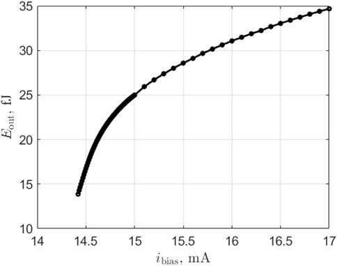
FIGURE 3. Output pulse energy vs bias current of the gain section for the laser-neuron. Self-pulsating threshold is ibias = 14.4 mA.
In order to highlight the neuronal behavior of the laser, we plot the time traces of the internal variables under different situations. The first case concerns the arrival in the SA of an excitatory pulse (of energy 60 fJ) and the triggering of an output spike event. Results are presented in Figure 4. At the input pulse arrival (t = 500ps), the SA photon population NSA (black curve in the left hand side graph) increases sharply then returns to zero as those photons are either absorbed or exit the SA section on the other side (the transit time through the SA is τph,inj in the lateral direction). These photons anyway, create a large number of carriers nSA (grey curve in the right hand side graph) that saturates the absorber. As the SA has a fast dynamics, it recovers almost immediately (first peak in the nSA curve), but not fully since the overall laser cavity gain increases in the meantime leading to a surge in the main photon population Nph (grey curve in the left hand side graph) and a new peak in the SA carrier concentration. This results in the laser output switching on and, consequently, the depletion of the gain sections’ carrier population nG and nQ due to the large stimulated emission occurring. Finally, the reducing nG closes the gain of the cavity, switching off the laser output and allowing the SA to recover fully its high loss state (nSA → 0) while nG and nQ slowly recover their steady state value thanks to the gain section bias current (rate 1/τG). During that time, the laser can hardly trigger a new spike event; this is the equivalent of the relative refractory period in the spiking neuron. The second case highlights the integration of excitation signals. Now, two pulses are sent to the SA section at t = 500ps and t = 600ps each with an energy of 30 fJ. Results are presented in Figure 5. The arrival of the first input pulse at t = 500ps, creates a surge in the SA carrier population as explained above. The SA loss drops and the main photon population increases slightly but not enough to lead to a spiking event as shown by the dashed curves representing the evolution of the parameters if only a single pulse had been sent. Upon the arrival of the second pulse, the SA carrier population increases again sharply and now reaches a level sufficiently high to trigger a spiking event followed by a refractory period during which the laser slowly recovers. Finally, we illustrate the inhibition of a spiking event. An inhibitory pulse of energy 60 fJ is sent into the gain quenching section at t = 500ps and then an excitatory pulse of energy 60 fJ is sent into the SA section at t = 600ps and no spiking event occurs. Results are presented in Figure 6. Following the reception of the inhibitory pulse, the photon population of the GQ section surges (black dash-dot curve in the left hand side graph). This triggers a sharp drop in the carrier concentration of this section (black dash-dot curve in the right hand side graph). As the lifetime of the GQ section photons is very short, NQ rapidly falls back to zero and the carrier concentration starts to recover. When the excitatory pulse reaches the SA at t = 600ps (black curve in the left hand side graph), the laser has not recovered yet and hence, although the carrier concentration of the SA section exhibits a large spike, there is only a small increase in the main photon population (gray curve in the left hand side graph) and no output spike is generated. Also, the carrier concentration of the main gain section nG (as shown by the black curve in the right hand side graph) is nearly not affected. After this illustration of the similarity in behavior between the proposed side light-injected Q-switch laser and an spiking neuron (excitation, recovery, integration and inhibition), we now perform a more general behavioral study.
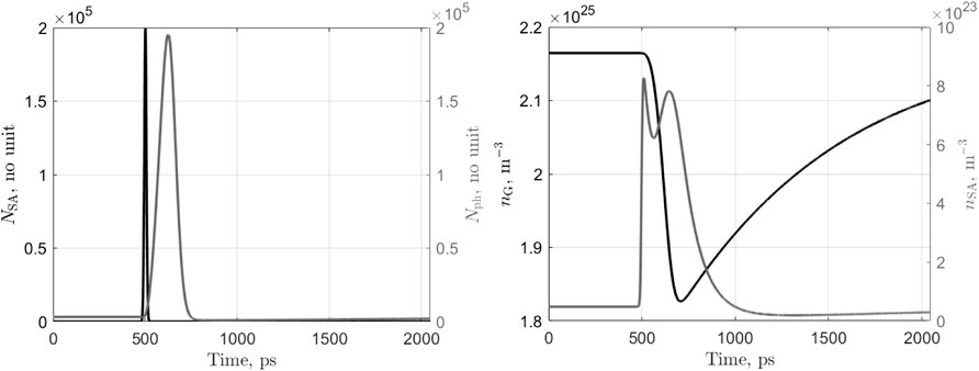
FIGURE 4. Time traces of the photons (left) and carriers (right) of the laser-neuron under ibias = 13 mA and upon the arrival at t = 500ps of an exitatory pulse (in the SA section) of energy 60 fJ.
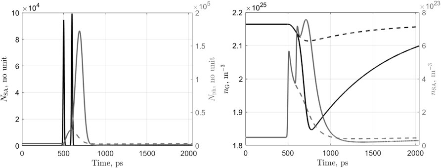
FIGURE 5. Time traces of the photons (left) and carriers (right) of the laser-neuron under ibias = 13 mA and upon the arrival at t = 500ps and 600ps of two exitatory pulses (in the SA section) each of energy 30 fJ. The dashed curves show the evolution of the parameters if only the first pulse had been present.
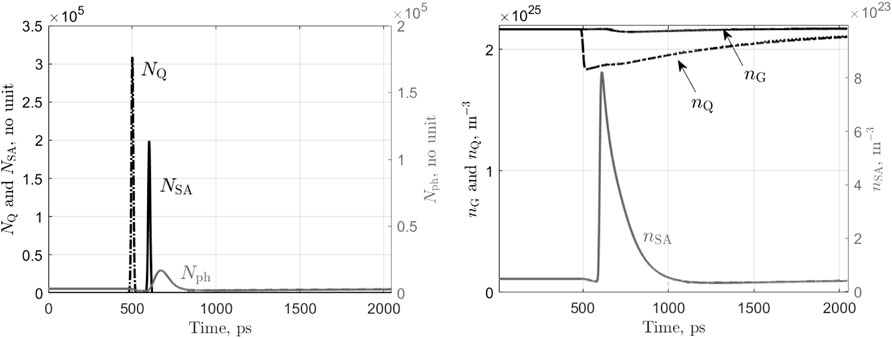
FIGURE 6. Time traces of the photons (left) and carriers (right) of the laser-neuron under ibias = 13 mA and upon the arrival at t = 500ps of an inhibitory pulse (in the GQ section) of energy 60 fJ then at 600 ps of an exitatory pulse (in the SA section) of energy 60 fJ.
Next, we study the excitability by computing the output pulse energy Eout and timing TS,out as a function of input pulse energy ESA,in when the neurons bias is set below its self-pulsating threshold (we use ibias = 13 mA). Results are shown in Figure 7. The input pulse consists of a Gaussian pulse of full width at half-maximum 55 ps matching the lasers output pulse characteristics. It enters the lateral waveguide connected to the SA part of the laser. We find that the excitation threshold of the spiking laser neuron is 48 pJ.
For input pulse energies above this value, the laser fires an output spike and under this value, it returns to its resting state.
As can be seen in 7 (top graph), the output pulse energy is not constant as can be expected from biological neurons but depends upon the input excitation strength. It can also be noted that the pulse output timing (7 bottom graph) decreases sharply above the threshold, then stabilizes around 70 ps after the input pulse arrival. This behavior, where the spike output timing is inversely proportional to the strength of the membrane voltage excitation, can also be found in neuron models such as the Hodgkin-Huxley and LIF ones [8].
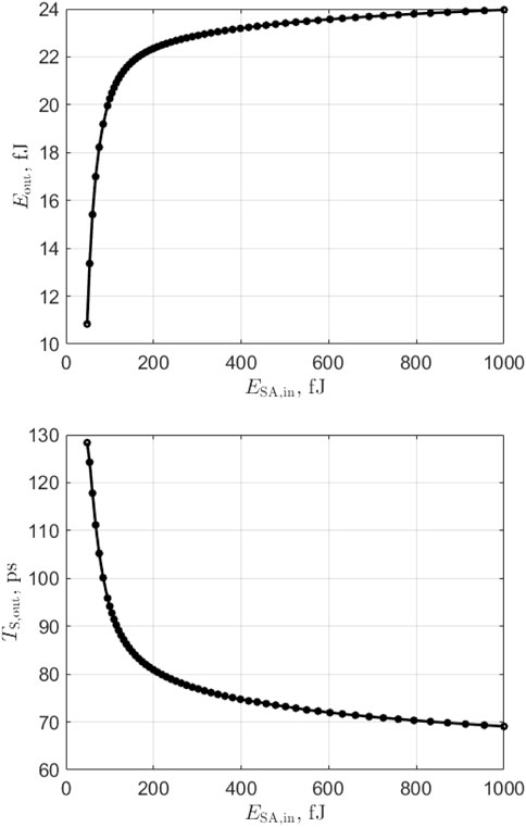
FIGURE 7. Simulation of output pulse energy (top) and spike timing (bottom) as a function of SA input pulse energy for ibias = 13 mA. A minimum input pulse energy of 48 fJ is required to trigger an output spike.
We now study the impact of sending an optical pulse on the gain quenching input. To do so, we plot (Figure 8) the pulse output energy Eout and timing TS,out as a function of the pulse energy EQ,in on the gain quenching section for various conditions of SA input pulse energy (above excitation threshold e.g. ESA,in > 48 fJ) for the same gain section bias (ibias = 13 mA). We thus can assess the inhibitory effect of the gain quenching section. Sending optical energy on the GQ section leads to a strong reduction of the output pulse energy or even a complete cancelation of the spiking event. The energy level required to suppress the spike event is about one order of magnitude lower than the required excitatory pulse energy to generate the output pulse. This can be explained by the high population inversion of the gain section and the strong stimulated emission created when the side light is input, multiplying the effect.
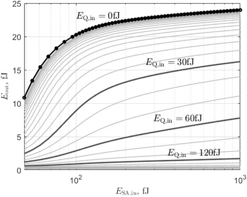
FIGURE 8. Simulation of output pulse energy as a function of SA input pulse energy for different GQ input pulse energy and for ibias = 13 mA.
Next, we look at the refractory period of the laser-neuron (Figure 9). To do so, we trigger a spike event by sending an input pulse of energy ESA,in (
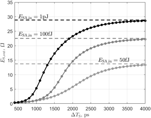
FIGURE 9. Simulation of output pulse energy as a function of SA input pulses energy for different delays between the input pulses and for ibias = 13 mA. The laser receives two input pulses (SA section) of equal energy ESA,in separated by ΔTS. In response it emits up to two output pulses. The first output pulse energy is plotted with a dash line while the second pulse energy is plotted with a thick line and symbols.
We now verify the cascadability in the presented neuron, as well as its optical memory properties. Cascadability can be defined as the ability of a laser to drive one or many other lasers. This characteristic is therefore a necessary condition to design a large scale photonic spiking neural network (PSNN). A demonstration of these two properties can be done using a system of two interconnected lasers as shown in Figure 10, also known as a multistable system [10]. Here, the two lasers are considered identical and are both polarized with ibias = 13 mA. They are also mutually coupled through an amplifier characterized by the coupling weight w = 5 (7 dB of optical gain), associated with a delay of τd = 2ns. Figure 11 shows the respective responses of the two lasers. The system is first turned on when an optical pulse of energy 100 fJ is injected into the first laser’s SA section (ON) at t = 200ps. The output spike of the laser is then amplified to allow the excitation of the second laser. This initiates both lasers to fire a train of spikes with a fixed period
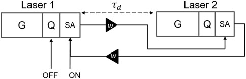
FIGURE 10. Cascadability circuit: two identical laser neurons are self-coupled with a delay of τd = 2ns and a gain of 7 dB (w = 5).
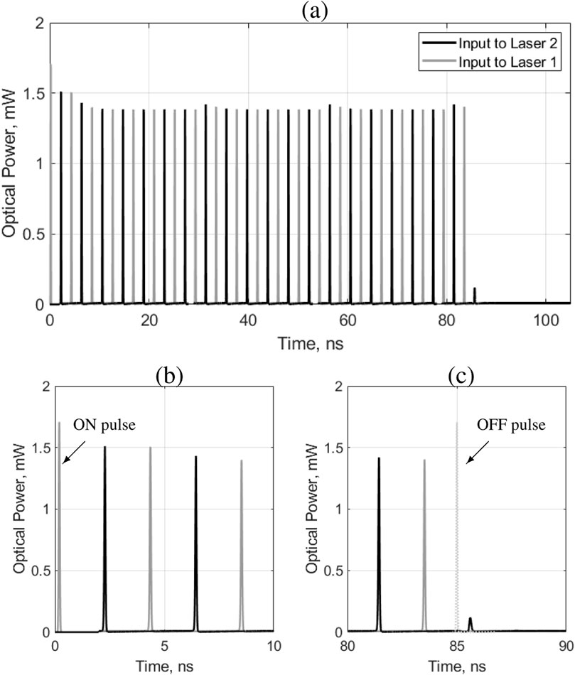
FIGURE 11. (A): Pulse train from two self-coupled laser neurons with 2ns delay and 7 dB of optical gain. Gray: input to laser 1 SA section. Black: input to laser 2 SA section. (B): focus on the start of the pulse train. (C): focus of the end of the pulse train.
In this paper, we have studied theoretically the use of a Q-switch laser with side light injection as an all-optical neuron for photonic spiking neural networks (PSNN). First, we have presented the Ordinary Differential Equations for the multi-section laser, including terms for the side light injection for gain quenching and saturable absorption. Then, solving numerically these equations, we have shown that the behaviour of the laser-neuron mimics that of spiking neuron (excitability, inhibitability, integration, refractoriness and cascadability) with ultrafast pico-second scale response and low power control signals. We have determined the self-pulsating and the optical excitability thresholds as well as quantified the inibitory effects and refractory period. Finally, we demonstrated the cascadability of the laser-neurons. Such all optical laser-neuron is suited for future high speed SNN hardware implementation especially considering integration platforms such as silicon photonics.
The raw data supporting the conclusion of this article will be made available by the authors, without undue reservation.
KM-O and BC contributed to the overall study and analysis and wrote the full paper. BR contributed some background work regarding the use of spiking neurons in general neuromorphic circuits.
This work was supported by the French Public Authorities in the frame of the Important Project of Common European Interest (IPCEI) on Microelectronics.
The authors declare that the research was conducted in the absence of any commercial or financial relationships that could be construed as a potential conflict of interest.
All claims expressed in this article are solely those of the authors and do not necessarily represent those of their affiliated organizations, or those of the publisher, the editors and the reviewers. Any product that may be evaluated in this article, or claim that may be made by its manufacturer, is not guaranteed or endorsed by the publisher.
1. Roy K, Jaiswal A, Panda P. Towards spike-based machine intelligence with neuromorphic computing. Nature (2019) 575:607–17. doi:10.1038/s41586-019-1677-2
2. Hendy H, Merkel C. Review of spike-based neuromorphic computing for brain-inspired vision: Biology, algorithms, and hardware. J Electron Imaging (2022) 31:010901. doi:10.1117/1.JEI.31.1.010901
3. Shastri BJ, Tait AN, de Lima TF, Nahmias MA, Peng H-T, Prucnal PR. Principles of neuromorphic photonics. arXiv:1801.00016 [physics] (2018) doi:10.1007/978-3-642-27737-5_702-1
4. Shastri BJ, Tait AN, Ferreira de Lima T, Pernice WHP, Bhaskaran H, Wright CD, et al. Photonics for artificial intelligence and neuromorphic computing. Nat Photon (2021) 15:102–14. doi:10.1038/s41566-020-00754-y
5. Ona KM, Charbonnier B, Hassan K. Design of an integrated iii–v on silicon semiconductor laser for spiking neural networks. In: 2021 IEEE International Interconnect Technology Conference (IITC) (2021). p. 1. doi:10.1109/IITC51362.2021.9537482
6. Szelag B, Hassan K, Adelmini L, Ribaud K, Roure MC, Sanchez L, et al. Cmos compatible iii-v/silicon laser integration on silicon photonics platform. In: 2019 IEEE Photonics Conference (IPC) (2019). p. 1. doi:10.1109/IPCon.2019.8908325
7. Vreeken J. Spiking neural networks, an introduction. Utrecht: Utrecht University: Information and Computing Sciences (2003). Technical report UU-CS-2003-008 , 5.
8. Gerstner W, Kistler WM. Spiking neuron models: Single neurons, populations, plasticity. Cambridge, U.K.; New York: Cambridge University Press (2002).
9. Zeng Y, Stewart TC, Ibne Ferdous Z, Berdichevsky Y, Guo X. Temporal learning with biologically fitted SNN models. In: International Conference on Neuromorphic Systems 2021. Knoxville: ACM (2021). p. 1–8. doi:10.1145/3477145.3477153
10. Nahmias MA, Shastri BJ, Tait AN, Prucnal PR. A leaky integrate-and-fire laser neuron for ultrafast cognitive computing. IEEE J Sel Top Quan Electron (2013) 19:1–12. doi:10.1109/JSTQE.2013.2257700
11. Shastri BJ, Nahmias MA, Tait AN, Rodriguez AW, Wu B, Prucnal PR. Spike processing with a graphene excitable laser. Sci Rep (2016) 6:19126. doi:10.1038/srep19126
12. Song ZW, Xiang SY, Ren ZX, Hong S, Wen AJ, Hao Y. Photonic spiking neural network based on excitable VCSELs-SA for sound azimuth detection. Opt Express (2020) 13:1561. doi:10.1364/oe.381229
13. Ueno M, Lang R. Conditions for self-sustained pulsation and bistability in semiconductor lasers. J Appl Phys (1985) 58:1689–92. doi:10.1063/1.336065
14. Xiang J, Torchy A, Guo X, Su Y. All-optical spiking neuron based on passive microresonator. J Lightwave Technol (2020) 38:4019–29. doi:10.1109/JLT.2020.2986233
15. Coomans W, Gelens L, Beri S, Danckaert J, Van der Sande G. Solitary and coupled semiconductor ring lasers as optical spiking neurons. Phys Rev E (2011) 84:036209. doi:10.1103/PhysRevE.84.036209
16. Selmi F, Braive R, Beaudoin G, Sagnes I, Kuszelewicz R, Barbay S. Relative refractory period in an excitable semiconductor laser. Phys Rev Lett (2014) 112:183902. doi:10.1103/PhysRevLett.112.183902
17. Shastri BJ, Nahmias MA, Tait AN, Wu B, Prucnal PR. Simpel: Circuit model for photonic spike processing laser neurons. Opt Express (2015) 23:8029–44. doi:10.1364/OE.23.008029
18. Nahmias MA, Tait AN, Shastri BJ, de Lima TF, Prucnal PR. Excitable laser processing network node in hybrid silicon: Analysis and simulation. Opt Express (2015) 23:26800–13. doi:10.1364/OE.23.026800
19. Tait AN, de Lima TF, Zhou E, Wu AX, Nahmias MA, Shastri BJ, et al. Neuromorphic photonic networks using silicon photonic weight banks. Sci Rep (2017) 7:7430. doi:10.1038/s41598-017-07754-z
20. Peng H-T, Angelatos G, de Lima TF, Nahmias MA, Tait AN, Abbaslou S, et al. Temporal information processing with an integrated laser neuron. IEEE J Sel Top Quan Electron (2020) 26:1–9. doi:10.1109/JSTQE.2019.2927582
21. Robertson J, Hejda M, Bueno J, Hurtado A. Ultrafast optical integration and pattern classification for neuromorphic photonics based on spiking VCSEL neurons. Sci Rep (2020) 10:6098. doi:10.1038/s41598-020-62945-5
22. Uenohara H, Kawamura Y, Iwamura H, Nonaka K, Tsuda H, Kurokawa T. Operation characteristics of a side-light-injection multiple-quantum-well bistable laser for all-optical switching. J Appl Phys (2008) (1994) 33:815–21. doi:10.1143/jjap.33.815
Keywords: spiking neural networks, artificial intelligence, leaky integrate and fire neuron, neuromorphic computing, silicon photonics
Citation: Mekemeza-Ona K, Routier B and Charbonnier B (2022) All optical Q-switched laser based spiking neuron. Front. Phys. 10:1017714. doi: 10.3389/fphy.2022.1017714
Received: 12 August 2022; Accepted: 02 November 2022;
Published: 16 November 2022.
Edited by:
Lorenzo Pavesi, University of Trento, ItalyReviewed by:
Brajesh Kumar Kaushik, Indian Institute of Technology Roorkee, IndiaCopyright © 2022 Mekemeza-Ona, Routier and Charbonnier. This is an open-access article distributed under the terms of the Creative Commons Attribution License (CC BY). The use, distribution or reproduction in other forums is permitted, provided the original author(s) and the copyright owner(s) are credited and that the original publication in this journal is cited, in accordance with accepted academic practice. No use, distribution or reproduction is permitted which does not comply with these terms.
*Correspondence: Benoît Charbonnier, YmVub2l0LmNoYXJib25uaWVyQGNlYS5mcg==
Disclaimer: All claims expressed in this article are solely those of the authors and do not necessarily represent those of their affiliated organizations, or those of the publisher, the editors and the reviewers. Any product that may be evaluated in this article or claim that may be made by its manufacturer is not guaranteed or endorsed by the publisher.
Research integrity at Frontiers
Learn more about the work of our research integrity team to safeguard the quality of each article we publish.